remove seats INFINITI QX56 2008 Factory User Guide
[x] Cancel search | Manufacturer: INFINITI, Model Year: 2008, Model line: QX56, Model: INFINITI QX56 2008Pages: 4083, PDF Size: 81.73 MB
Page 3080 of 4083

SB-12
< ON-VEHICLE REPAIR >
SEAT BELTS
4. Check the shoulder seat belt guide and shoulder belt height adjuster for\
front seats. Ensure guide swivelsfreely and that belt lays flat and does not bind in guide. Ensure height adjuster operates properly and
holds securely.
5. Check retractor operation:
a. Fully extend the seat belt webbing and check for twists, tears or other damage.
b. Allow the seat belt to retract. Ensure that belt retu rns smoothly and completely into the retractor. If the
seat belt does not return smoothly, wipe the inside of the loops with a clean paper cloth, because dirt built
up in the loops of the upper anchors can c ause the seat belts to retract slowly.
c. Fasten the seat belt. Check the seat belt returns smoothly and completely to the retractor. If the belt does not return smoothly, the cause may be an accumulati on of dust or dirt. Use the “SEAT BELT TAPE SET”
and perform the following steps.
Inspect the front seat belt through-anchor:1. Pull the seat belt out to a length of 500 mm (19.69 in) or more.
2. Use a clip or other device to hold the seat belt at the center pillar belt opening.
3. Pass a thin wire through the through-anchor belt opening. Hold both ends of the wire and pull taut while moving it up and down several times along the belt opening surface to remove dirt.
4. Any dirt that cannot be removed with the wir e can be removed by cleaning the opening with a clean
cloth.
5. Apply tape at the point where the belt contacts the through-anchor belt opening.
NOTE:
Apply the tape so that there is no looseness or wrinkling.
6. Remove the clip holding the seat belt and check that the belt returns smoothly.
7. Repeat steps above as necessary to check the other seat belts.
SEAT BELT RETRACTOR ON-VEHICLE CHECK
Emergency Locking Retractors (ELR) and Automatic Locking Retractors (ALR)
NOTE:
All seat belt retractors are of the Emergency Locking Retractors (ELR) type. In an emergency (sudden stop)
the retractor will lock and prevent the belt from ext ending any further. All 3-point type seat belt retractors
except the driver's seat belt also have an Automati c Locking Retractors (ALR) mode. The ALR mode (also
called child restraint mode) is used when installing child seats. The ALR mode is activated when the seat belt
is fully extended. When the belt is then retracted partiall y, the ALR mode automatically locks the seat belt in a
specific position so the belt cannot be extended any furt her. To cancel the ALR mode, allow the seat belt to
fully wind back into the retractor.
Check the seat belt retractors using the following test(s ) to determine if a seat belt retractor and belt assembly
is operating properly.
ELR Function Stationary Check
Grasp the shoulder belt and pull forward quickly. The re tractor should lock and prevent the belt from extending
further.
ALR Function Stationary Check
1. Pull out entire length of seat belt from retractor until a click is heard.
2. Retract the belt partially. A clicking noise should be hear d as the belt retracts indicating that the retractor is
in the Automatic Locking Retractor (ALR) mode.
3. Grasp the seat belt and try to pull out the retractor. The belt must lock and not extend any further. If neces-
sary replace the seat belt retractor and belt assembly.
4. Allow the entire length of the belt to re tract to cancel the automatic locking mode.
ELR Function Moving Check
WARNING:
Perform the following test in a safe, open area clear of other vehicles and obstructions (for example, a
large, empty parking lot). Road surface must be p aved and dry. DO NOT perform the following test on
wet or gravel roads or on public streets and highw ays. This could result in an accident and serious
personal injury. The driver and passenger must be prepared to brace themselves in the event the
retractor does not lock.
1. Fasten drivers seat belt. Buckle a passenger in to the seat for the belt that is to be tested.
Revision: March 2010 2008 QX56
Page 3127 of 4083

INSPECTION AND ADJUSTMENTSE-5
< BASIC INSPECTION >
C
DE
F
G H
I
K L
M A
B
SE
N
O P
INSPECTION AND ADJUSTMENT
Preliminary CheckINFOID:0000000001735710
1.FOREIGN OBJECTS
Check the following:
• objects on or behind the seats that could cause binding
• objects under the seats that may be in terfering with the seat’s moving parts
Are there any foreign objects that could be causing interference with the seats?
YES >> Remove objects.
NO >> GO TO 2.
2.WIRING CONNECTIONS
1. Disconnect third row power folding seat c ontrol unit and seat motor harness connectors.
2. Check terminals for damage or loose connections.
3. Reconnect harness connectors.
Are any connectors damaged or loose?
YES >> Repair or replace damaged parts.
NO >> GO TO 3.
3.POWER AND GROUND
Check power supply and ground circuits for third row power folding seat control unit. Refer to SE-18, "
Power
Supply and Ground Circuit Check for Third Row Power Folding Seat Control Unit".
Is the inspection result normal?
YES >> Refer to SE-28, "DTC Index".
NO >> Repair or replace as necessary.
Revision: March 2010 2008 QX56
Page 3166 of 4083

SE-44
< PRECAUTION >
PRECAUTIONS
5. When the repair work is completed, return the ignition switch to the ″LOCK ″ position before connecting
the battery cables. (At this time, the steering lock mechanism will engage.)
6. Perform a self-diagnosis check of a ll control units using CONSULT-III.
Precaution for WorkINFOID:0000000001735735
• When removing or disassembling each component, be careful not to damage or deform it. If a component
may be subject to interference, be sure to protect it with a shop cloth.
• When removing (disengaging) components with a screwdriver or similar tool, be sure to wrap the component
with a shop cloth or vinyl tape to protect it.
• Protect the removed parts with a shop cloth and keep them.
• Replace a deformed or damaged clip.
• If a part is specified as a non-reusable part, always replace it with new one.
• Be sure to tighten bolts and nuts securely to the specified torque.
• After re-installation is completed, be sure to check that each part works normally.
• Follow the steps below to clean components.
- Water soluble foul: Dip a soft cloth into lukewarm water, and wring the water out of the cloth to wipe the fouled area.
Then rub with a soft and dry cloth.
- Oily foul: Dip a soft cloth into lukewarm water wit h mild detergent (concentration: within 2 to 3%), and wipe
the fouled area.
Then dip a cloth into fresh water, and wring the water out of the cloth to wipe the detergent off. Then rub with
a soft and dry cloth.
• Do not use organic solvent such as thinner, benzene, alcohol, or gasoline.
• For genuine leather seats, use a genuine leather seat cleaner.
Revision: March 2010 2008 QX56
Page 3171 of 4083

FRONT SEATSE-49
< ON-VEHICLE REPAIR >
C
DE
F
G H
I
K L
M A
B
SE
N
O P
Removal and InstallationINFOID:0000000001606205
REMOVAL
When removing or installing the seat trim, handle it carefully to keep dirt out and avoid damage.
CAUTION:
• Before removing the front seat, turn the ignition switch off, disconnect both battery cables and wait
at least 3 minutes.
• When checking the power seat circuit for continuity using a circuit tester, do not confuse its connec-
tor with the side air bag module connector. Su ch an error may cause the air bag to deploy.
• Do not drop, tilt, or bump the side air bag modul e while installing the seat. Always handle it with
care.
• After front side air bag module inflat es, front seatback assembly must be replaced.
• Front passenger seat is equipped with an Occupant Classification System sensor and control mod-
ule. Do not disassemble front passenger seat cushion assembly or remove the trim as this will affect
the Occupant Classificatio n System calibration.
• Always replace passenger seat cushion as an assembly.
1. Slide the seat until the four body mounting bolts are visible and a tool can be inserted.
NOTE:
• If disassembling the seat after removal, set the front/rear cushion lifters to the top position.
2. Disconnect both battery cables and wait at least 3 minutes.
3. Disconnect the side air bag module harness connector.
4. Remove the four body mounting bolts.
5. Disconnect the power seat harness connectors and remove the seat from the vehicle.
NOTE:
When removing and installing the seat, use shop cloths to protect the vehicle from damage.
INSTALLATION
• Installation is in the reverse order of removal.
19. Outer pedestal finisher20. Seat cushion outer finisher21. Seat cushion assembly
22. Power seat switch escutcheon 23. Slide switch knob 24. Recliner switch knob
25. Seatback assembly 26. Headrest holder27. Seat slide/ recline switch
28. Power lumbar switch
Revision: March 2010 2008 QX56
Page 3181 of 4083

THIRD SEATSE-59
< ON-VEHICLE REPAIR >
C
DE
F
G H
I
K L
M A
B
SE
N
O P
RH Side SeatINFOID:0000000001606220
REMOVAL
1. Remove the storage bin. Refer to INT-19, "Removal and Installation".
2. Remove the lower base trim covers.
3. Remove front link nuts (A) and RH hinge front bolt (B).
4. Remove push pin (2) and release elastic band (3) from seat frame (1).
•⇐ : Vehicle front
5. Partially lift seatback upright, then remove seat belt buckle (2) from between hinge cover (1) and seat cushion side facing (3).
•⇐ : Vehicle front
6. Retract the seat into the cargo floor position.
7. Remove the rear bolts from the seat assembly.
8. Remove the seat assembly.
INSTALLATION
Installation is in the reverse order of removal. Front link nuts : 45 N·m (4.6 Kg-m, 33 ft-lb)
RH hinge front bolt : 45 N·m (4.6 Kg-m, 33 ft-lb)
LIIA2326E
LHIA0105E
LHIA0106E
Seat hinge rear bolt : 45 N·m (4.6 Kg-m, 33 ft-lb)
LIIA2327E
Revision: March 2010
2008 QX56
Page 3185 of 4083

THIRD SEATSE-63
< ON-VEHICLE REPAIR >
C
DE
F
G H
I
K L
M A
B
SE
N
O P
7. Remove the seat hinge rear bolt (A) and seat belt buckle bolt (B) from the seat assembly.
CAUTION:
Discard the seat belt buckle bolt and use a new bolt for
installation.
8. Disconnect the seat harness.
9. Remove the seat assembly.
INSTALLATION
Installation is in the reverse order of removal.
Power seat cross beamINFOID:0000000001606224
REMOVAL
1. Remove the lower seat mount bolts.
2. Fold the seat cushion up.
3. Remove the harness connectors from the seat control unit.
4. Press the front release tab and remove the seat crontrol unit. Seat hinge rear bolt (A) : 45 N·m (4.6 Kg-m, 33 ft-lb
Seat belt buckle bolt (B) : 48 N·m (4.9 Kg-m, 35 ft-lb
LIIA2325E
ALIIA0096GB
ALIIA0097ZZ
ALIIA0098ZZ
Revision: March 2010
2008 QX56
Page 3189 of 4083

THIRD SEATSE-67
< ON-VEHICLE REPAIR >
C
DE
F
G H
I
K L
M A
B
SE
N
O P
RH Side SeatINFOID:0000000001606225
REMOVAL
1. Remove the storage bin. Refer to INT-19, "Removal and Installation".
2. Remove the lower base trim covers.
3. Remove front link nuts (A) and RH hinge front bolt (B).
4. Remove push pin (2) and release elastic band (3) from seat frame (1).
•⇐ : Vehicle front
5. Partially lift seatback upright, then remove seat belt buckle (2) from between hinge cover (1) and seat cushion side facing (3).
•⇐ : Vehicle front
6. Retract the seat into the cargo floor position.
7. Remove the rear bolts from the seat assembly.
8. Disconnect the seat harness.
9. Remove the seat assembly.
INSTALLATION
Installation is in the reverse order of removal.
LIIA2326E
LHIA0105E
LHIA0106E
LIIA2327E
Revision: March 2010 2008 QX56
Page 3193 of 4083

FRONT SEATSE-71
< DISASSEMBLY AND ASSEMBLY >
C
DE
F
G H
I
K L
M A
B
SE
N
O P
Disassembly and AssemblyINFOID:0000000001606212
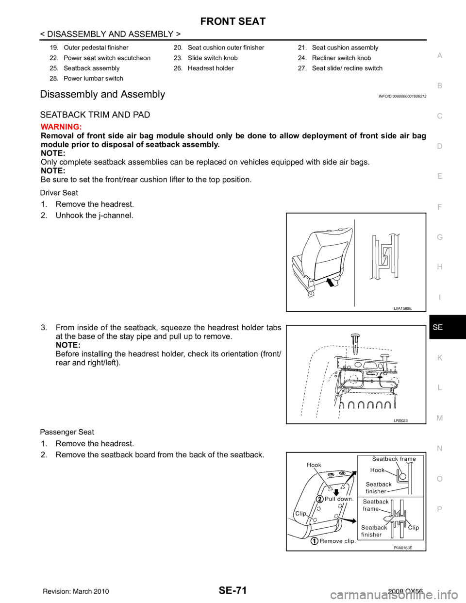
SEATBACK TRIM AND PAD
WARNING:
Removal of front side air bag module should only be done to allow deployment of front side air bag
module prior to disposal of seatback assembly.
NOTE:
Only complete seatback assemblies can be replaced on vehicles equipped with side air bags.
NOTE:
Be sure to set the front/rear cushion lifter to the top position.
Driver Seat
1. Remove the headrest.
2. Unhook the j-channel.
3. From inside of the seatback, squeeze the headrest holder tabs
at the base of the stay pipe and pull up to remove.
NOTE:
Before installing the headrest holder, check its orientation (front/
rear and right/left).
Passenger Seat
1. Remove the headrest.
2. Remove the seatback board from the back of the seatback.
19. Outer pedestal finisher 20. Seat cushion outer finisher21. Seat cushion assembly
22. Power seat switch escutcheon 23. Slide switch knob 24. Recliner switch knob
25. Seatback assembly 26. Headrest holder27. Seat slide/ recline switch
28. Power lumbar switch
LIIA1580E
LRS023
PIIA0163E
Revision: March 2010 2008 QX56
Page 3195 of 4083

FRONT SEATSE-73
< DISASSEMBLY AND ASSEMBLY >
C
DE
F
G H
I
K L
M A
B
SE
N
O P
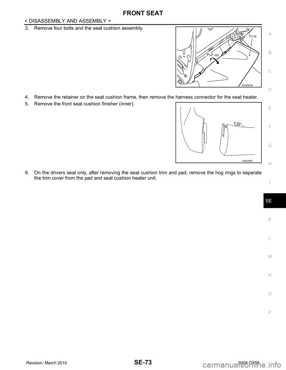
3. Remove four bolts and the seat cushion assembly.
4. Remove the retainer on the seat cushion frame, then remove the harness connector for the seat heater.
5. Remove the front seat cushion finisher (inner).
6. On the drivers seat only, after removing the seat cushion trim and pad, remove the hog rings to separate the trim cover from the pad and seat cushion heater unit.
SIIA0503E
LIIA0285E
Revision: March 2010 2008 QX56
Page 3857 of 4083

HEATER & COOLING UNIT ASSEMBLYVTL-17
< ON-VEHICLE REPAIR >
C
DE
F
G H
J
K L
M A
B
VTL
N
O P
1. Move the two front seats to the rear most position on the seat track.
2. Disconnect the battery negative terminal and battery positive terminal.
3. Discharge the refrigerant from the A/C system. Refer to HA-20, "
HFC-134a (R-134a) Service Procedure".
4. Drain the coolant from the engine cooling system. Refer to CO-11, "
Changing Engine Coolant".
5. Disconnect the front heater hoses from the front heater core.
6. Disconnect the high/low pressure pipes from the front expansion valve.
7. Remove the instrument panel and console panel. Refer to IP-12, "
Removal and Installation".
8. Remove the steering column. Refer to ST-20, "
Removal and Installation".
9. Disconnect the instrument panel wire harness at t he RH and LH in-line connector brackets, and the fuse
block (J/B) electrical connectors. Refer to PG-9, "
Wiring Diagram — Battery Power Supply —".
10. Disconnect the steering member from each side of the vehicle body.
11. Remove the front heater and cooling unit assembly with it attached to the steering member, from the vehi- cle.
CAUTION:
Use care not to damage the seats and interior trim panels when removing the front heater and
cooling unit assembly with it at tached to the steering member.
12. Remove the front heater and cooling uni t assembly from the steering member.
Installation
Installation is in the reverse order of removal.
CAUTION:
• Replace the O-ring of the low-pressure pipe and high-pressure pipe with a new one, and apply com-
pressor oil to it when installing it.
• After charging the refrigerant, check for leaks.
NOTE:
• Fill the engine cooling system with the specified coolant mixture. Refer to CO-11, "
Changing Engine Cool-
ant".
• Recharge the A/C system. Refer to HA-20, "
HFC-134a (R-134a) Service Procedure".
REAR HEATER AND COOLING UNIT ASSEMBLY
Removal
1. Discharge the refrigerant from the A/C system. Refer to HA-20, "HFC-134a (R-134a) Service Procedure".
2. Drain the coolant from the engine cooling system. Refer to CO-11, "
Changing Engine Coolant".
3. Remove the luggage side finisher lower RH. Refer to INT-19, "
Removal and Installation".
4. Disconnect the rear heater core hoses from the rear heater core.
5. Disconnect the rear A/C pipes from the rear expansion valve.
6. Disconnect the following electrical connectors: • Rear blower motor
• Rear variable blower control
• Rear air mix door motor
7. Disconnect the ducts from the rear heater and cooling unit assembly.
8. Remove the rear heater and cooling unit assembly.
Installation
Installation is in the reverse order of removal.
CAUTION:
• Replace the O-ring of the low-pressure pipe and high-pressure pipe with a new one, and apply com- pressor oil to it when installing it.
• After charging the refrigerant, check for leaks.
NOTE:
• Fill the engine cooling system with the specified coolant mixture. Refer to CO-11, "
Changing Engine Cool-
ant".
• Recharge the A/C system. Refer to HA-20, "
HFC-134a (R-134a) Service Procedure".
Revision: March 2010 2008 QX56