tow INFINITI QX56 2008 Factory Owner's Manual
[x] Cancel search | Manufacturer: INFINITI, Model Year: 2008, Model line: QX56, Model: INFINITI QX56 2008Pages: 4083, PDF Size: 81.73 MB
Page 2023 of 4083

TRAILER TOWEXL-95
< COMPONENT DIAGNOSIS >
C
DE
F
G H
I
J
K
M A
B
EXL
N
O P
ABLIA2476GB
Revision: March 2010 2008 QX56
Page 2024 of 4083

EXL-96
< COMPONENT DIAGNOSIS >
TRAILER TOW
ABLIA2477GB
Revision: March 20102008 QX56
Page 2025 of 4083

TRAILER TOWEXL-97
< COMPONENT DIAGNOSIS >
C
DE
F
G H
I
J
K
M A
B
EXL
N
O P
ABLIA2478GB
Revision: March 2010 2008 QX56
Page 2026 of 4083

EXL-98
< COMPONENT DIAGNOSIS >
TRAILER TOW
ABLIA2479GB
Revision: March 20102008 QX56
Page 2038 of 4083

EXL-110
< ON-VEHICLE REPAIR >
ADJUSTMENT AND INSPECTION
ON-VEHICLE REPAIR
ADJUSTMENT AND INSPECTION
HEADLAMP
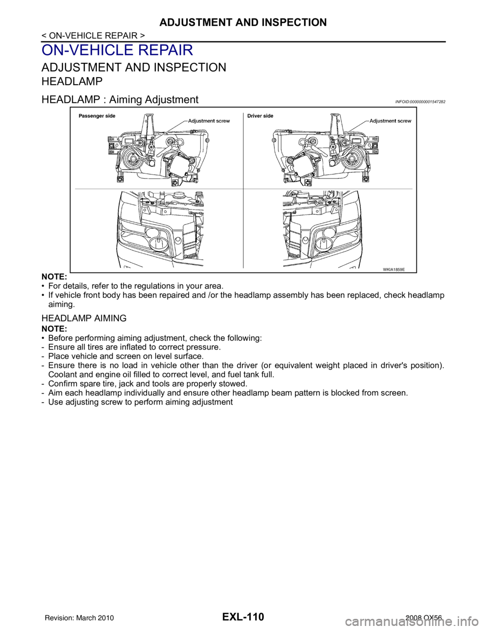
HEADLAMP : Aiming AdjustmentINFOID:0000000001547282
NOTE:
• For details, refer to the regulations in your area.
• If vehicle front body has been repaired and /or the headlamp assembly has been replaced, check headlamp
aiming.
HEADLAMP AIMING
NOTE:
• Before performing aiming adjustment, check the following:
- Ensure all tires are inflated to correct pressure.
- Place vehicle and screen on level surface.
- Ensure there is no load in vehicle other than the driver (or equivalent weight placed in driver's position).
Coolant and engine oil filled to correct level, and fuel tank full.
- Confirm spare tire, jack and tools are properly stowed.
- Aim each headlamp individually and ensure other headlamp beam pattern is blocked from screen.
- Use adjusting screw to perform aiming adjustment
WKIA1859E
Revision: March 2010 2008 QX56
Page 2047 of 4083

LIGHTING & TURN SIGNAL SWITCHEXL-119
< REMOVAL AND INSTALLATION >
C
DE
F
G H
I
J
K
M A
B
EXL
N
O P
LIGHTING & TURN SIGNAL SWITCH
Removal and InstallationINFOID:0000000001547172
REMOVAL
1. Remove steering column cover.
2. While pressing tabs, pull lighting and turn signal switch toward driver door and disconnect from the base.
INSTALLATION
Installation is in the reverse order of removal.
LKIA0013E
Revision: March 2010 2008 QX56
Page 2069 of 4083

EXT-16
< SERVICE INFORMATION >
REAR BUMPER
REMOVAL
1. Disconnect the negative battery terminals.
2. Remove the rear combination lamps LH and RH. Refer to EXL-124, "
Removal and Installation".
3. Remove the rear fascia assembly screws under the rear combination lamps LH and RH.
4. Remove the quarter panel trim covers LH and RH.
5. Disconnect the sonar sensor harness c onnector under the rear fascia assembly.
6. Release the retainer clips on both sides of the rear fascia assembly with a 1/4 turn and top S clips and remove the fascia assembly.
7. Detach the I-key antenna from the energy absorber.
8. Remove the energy absorber.
9. Remove the reinforcement assembly.
10. Remove the nuts and remove the retainer assembly. • Remove the S clips from the retainer assembly.
11. Disconnect the sonar sensors from the sonar sensor retainers.
12. Remove the sonar sensors and harness from the rear fascia assembly. • Disconnect the sonar sensors from the harness.
• Remove the sonar sensor retainers from the rear fascia assembly.
13. Remove the bolts on each side of the tow hitch and remove the tow hitch.
14. Remove the drafter duct from under the LH quarter panel.
INSTALLATION
Installation is in the reverse order of removal.
10. Rear fascia assembly 11. Sonar sensor retainer12. Reinforcement assembly
13. Tow hitch 14. Quarter panel trim cover RH
Revision: March 2010 2008 QX56
Page 2096 of 4083

FAX-12
< DISASSEMBLY AND ASSEMBLY >
DRIVE SHAFT
4. Remove the snap ring, then remove the ball cage, steel ball,inner race assembly from the drive shaft.
5. Remove the boot from the drive shaft.
6. Remove any old grease on the housing using paper towels.
Wheel Side
1. Mount the drive shaft in a vise. CAUTION:
When mounting the drive shaft in a vise, use copp er or aluminum plates between the vise and the
drive shaft.
2. Remove the boot bands, then remove the boot from the joint sub-assembly.
3. Screw a suitable drive shaft puller 30 mm (1.18 in) or more into the threaded part of the joint sub-assembly. Pull the joint sub-
assembly off of the drive shaft as shown.
NOTE:
Align the sliding hammer and drive shaft and remove the joint
sub-assembly by pulling straight out.
CAUTION:
• If the joint sub-assembly cannot be removed after five ormore attempts, replace the drive shaft and joint sub-
assembly as a set.
4. Remove the boot from the drive shaft.
5. Remove the circlip from the drive shaft.
6. While rotating the ball cage, remove any old grease from the joint sub-assembly using paper towels.
INSPECTION AFTER DISASSEMBLY
Drive Shaft
• Replace the drive shaft if there is any runout, cracking, or other damage.
Joint Sub-assembly
• Check for any rough rotation or unusual axial looseness.
• Clean any foreign material from inside the joint sub-assembly.
• Check for any compression scars, cracks, or fractures.
CAUTION:
If any defective conditions are found in the joint sub-assembly comp onents, replace the entire joint
sub-assembly.
Sliding Joint Side Housing
• Check for any compression scars, cracks, fracture s, or unusual wear on the ball rolling surface.
• Check for any damage to the drive shaft screws.
• Check for any deformation of the boot installation components.
Ball Cage
• Check the sliding surface for any compression scars, cracks, or fractures.
Steel Ball
• Check for any compression scars, cr acks, fractures, or unusual wear.
Inner Race
SFA514A
SDIA0606E
Revision: March 2010 2008 QX56
Page 2143 of 4083

GI-1
GENERAL INFORMATION
C
DE
F
G H
I
J
K L
M B
GI
SECTION GI
N
O P
CONTENTS
GENERAL INFORMATION
HOW TO USE THIS MANU AL ......................3
HOW TO USE THIS MANUAL ....................... .....3
Description .......................................................... ......3
Terms ........................................................................3
Units ..........................................................................3
Contents ....................................................................3
Relation between Illustrations and Descriptions .......4
Components ..............................................................4
HOW TO FOLLOW TROUBLE DIAGNOSES .....6
Description ................................................................6
How to Follow Test Groups in Trouble Diagnosis ......6
Key to Symbols Signifying Measurements or Pro-
cedures ............................................................... ......
7
HOW TO READ WIRING DIAGRAMS ................9
Connector symbols ............................................. ......9
Sample/wiring diagram -example- ...........................10
Description ..............................................................11
ABBREVIATIONS .......................................... ....13
Abbreviation List .................................................. ....13
TIGHTENING TORQUE OF STANDARD
BOLTS ................................................................
14
Tightening Torque Table .........................................14
RECOMMENDED CHEMICAL PRODUCTS
AND SEALANTS ............................................ ....
15
Recommended Chemical Products and Sealants ....15
TERMINOLOGY .................................................16
SAE J1930 Terminology List ............................... ....16
FEATURES OF NEW MODEL .....................20
IDENTIFICATION INFORMATION .....................20
Model Variation ................................................... ....20
Identification Number ..............................................21
Identification Plate ...................................................22
Dimensions .............................................................23
Wheels & Tires .................................................... ....23
PRECAUTION ..............................................24
PRECAUTIONS .................................................24
Description ........................................................... ....24
Precaution for Supplemental Restraint System
(SRS) "AIR BAG" and "SEAT BELT PRE-TEN-
SIONER" .................................................................
24
Precaution Necessary for Steering Wheel Rota-
tion After Battery Disconnect ...................................
24
Procedures without Cowl Top Cover .......................25
General Precautions ................................................25
Three Way Catalyst .................................................27
Precaution for Fuel (Unleaded Premium Gasoline
Recommended) .......................................................
27
Multiport Fuel Injection System or Engine Control
System .....................................................................
27
Hoses ......................................................................27
Engine Oils ..............................................................28
Air Conditioning .......................................................29
LIFTING POINT .................................................30
Pantograph Jack ......................................................30
Garage Jack and Safety Stand ................................30
2-Pole Lift ................................................................30
TOW TRUCK TOWING .....................................32
Tow Truck Towing ...................................................32
Vehicle Recovery (Freeing a stuck vehicle) ............33
BASIC INSPECTION ...................................34
SERVICE INFORMATION FOR ELECTRICAL
INCIDENT ..........................................................
34
Work Flow ............................................................ ....34
Control Units and Electrical Parts ............................34
How to Check Terminal ...........................................35
Intermittent Incident ............................................. ....38
Circuit Inspection .....................................................41
CONSULT-III CHECKING SYSTEM .................46
Revision: March 2010 2008 QX56
Page 2174 of 4083

GI-32
< PRECAUTION >
TOW TRUCK TOWING
TOW TRUCK TOWING
Tow Truck TowingINFOID:0000000004900863
WARNING:
• Never get under the vehicle while it is supported only by the jack. Always use safety stands to sup-
port the frame when you have to get under the vehicle.
• Place wheel chocks at both front an d back of the wheels on the ground.
CAUTION:
• All applicable local laws regarding the towing operation must be obeyed.
• It is necessary to use proper towing equipment to avoid possible damage during towing operation.
Towing is in accordance with Towing Procedure Manual at dealer.
• Always attach safety chains before towing.
• When towing, make sure that the transmission, steering system and power train are in good order. If
any unit is damaged, dollies must be used.
• Never tow an automatic transmission model from the rear
(i.e., backward) with four wh eels on the ground as this may
cause serious and expensive dama ge to the transmission.
4WD MODEL
INIFINTI does not recommend towing automatic transmi ssion equipped vehicles with the drive wheels on the
ground.
CAUTION:
• Never tow 4WD models with any of the tires on the ground as this may cause serious and expensive
damage to the transfer case and transmission.
Towiing Point
CAUTION:
WAIA0030E
WAIA0032E
Revision: March 2010 2008 QX56