instrument panel INFINITI QX56 2008 Factory Service Manual
[x] Cancel search | Manufacturer: INFINITI, Model Year: 2008, Model line: QX56, Model: INFINITI QX56 2008Pages: 4083, PDF Size: 81.73 MB
Page 1 of 4083

A
B
C
D
E
F
G
H
I
J
K
L
M
N
P
O
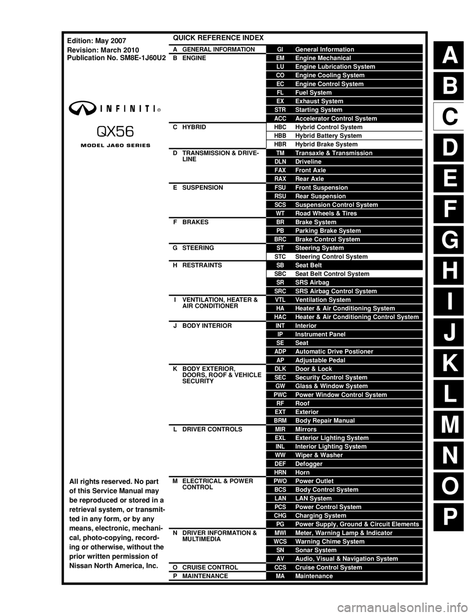
QUICK REFERENCE INDEX
AGENERAL INFORMATIONGIGeneral Information
BENGINEEMEngine Mechanical
LUEngine Lubrication System
COEngine Cooling System
ECEngine Control System
FLFuel System
EXExhaust System
STRStarting System
ACCAccelerator Control System
CHYBRIDHBCHybrid Control System
HBBHybrid Battery System
HBRHybrid Brake System
DTRANSMISSION & DRIVE-
LINETMTransaxle & Transmission
DLNDriveline
FAXFront Axle
RAXRear Axle
ESUSPENSIONFSUFront Suspension
RSURear Suspension
SCSSuspension Control System
WTRoad Wheels & Tires
FBRAKESBRBrake System
PBParking Brake System
BRCBrake Control System
GSTEERINGSTSteering System
STCSteering Control System
HRESTRAINTSSBSeat Belt
SBCSeat Belt Control System
SRSRS Airbag
SRCSRS Airbag Control System
IVENTILATION, HEATER &
AIR CONDITIONERVTLVentilation System
HAHeater & Air Conditioning System
HACHeater & Air Conditioning Control System
JBODY INTERIORINTInterior
IPInstrument Panel
SESeat
ADPAutomatic Drive Postioner
APAdjustable Pedal
KBODY EXTERIOR,
DOORS, ROOF & VEHICLE
SECURITYDLKDoor & Lock
SECSecurity Control System
GWGlass & Window System
PWCPower Window Control System
RFRoof
EXTExterior
BRMBody Repair Manual
LDRIVER CONTROLSMIRMirrors
EXLExterior Lighting System
INLInterior Lighting System
WWWiper & Washer
DEFDefogger
HRNHorn
MELECTRICAL & POWER
CONTROLPWOPower Outlet
BCSBody Control System
LANLAN System
PCSPower Control System
CHGCharging System
PGPower Supply, Ground & Circuit Elements
NDRIVER INFORMATION &
MULTIMEDIAMWIMeter, Warning Lamp & Indicator
WCSWarning Chime System
SNSonar System
AVAudio, Visual & Navigation System
OCRUISE CONTROLCCSCruise Control System
PMAINTENANCEMAMaintenance
All rights reserved. No part
of this Service Manual may
be reproduced or stored in a
retrieval system, or transmit-
ted in any form, or by any
means, electronic, mechani-
cal, photo-copying, record-
ing or otherwise, without the
prior written permission of
Nissan North America, Inc.
Edition: May 2007
Revision: March 2010
Publication No. SM8E-1J60U2
Page 24 of 4083

ADP-10
< FUNCTION DIAGNOSIS >
AUTOMATIC DRIVE POSITIONER SYSTEM
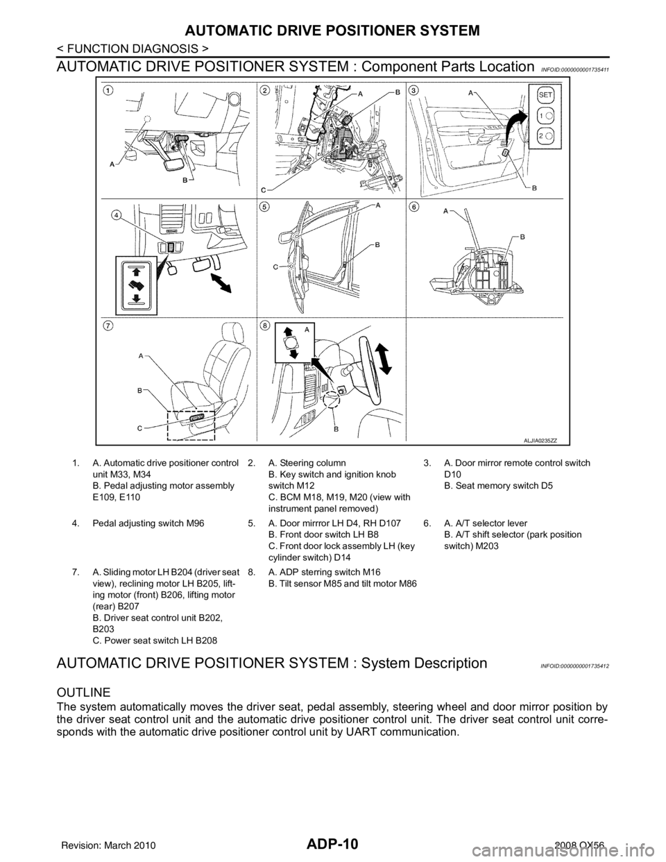
AUTOMATIC DRIVE POSITIONER SYSTEM : Component Parts Location
INFOID:0000000001735411
AUTOMATIC DRIVE POSITIONER SYSTEM : System DescriptionINFOID:0000000001735412
OUTLINE
The system automatically moves the driver seat, pedal assembly, steering wheel and door mirror position by
the driver seat control unit and the automatic drive posit ioner control unit. The driver seat control unit corre-
sponds with the automatic drive positioner control unit by UART communication.
ALJIA0235ZZ
1. A. Automatic drive positioner control
unit M33, M34
B. Pedal adjusting motor assembly
E109, E110 2. A. Steering column
B. Key switch and ignition knob
switch M12
C. BCM M18, M19, M20 (view with
instrument panel removed) 3. A. Door mirror remo
te control switch
D10
B. Seat memory switch D5
4. Pedal adjusting switch M96 5 . A. Door mirrror LH D4, RH D107
B. Front door switch LH B8
C. Front door lock assembly LH (key
cylinder switch) D14 6. A. A/T selector lever
B. A/T shift selector (park position
switch) M203
7. A. Sliding motor LH B204 (driver seat
view), reclining motor LH B205, lift-
ing motor (front) B206, lifting motor
(rear) B207
B. Driver seat control unit B202,
B203
C. Power seat switch LH B208 8. A. ADP sterring switch M16
B. Tilt sensor M85 and tilt motor M86
Revision: March 2010 2008 QX56
Page 29 of 4083

AUTOMATIC DRIVE POSITIONER SYSTEMADP-15
< FUNCTION DIAGNOSIS >
C
DE
F
G H
I
K L
M A
B
ADP
N
O P
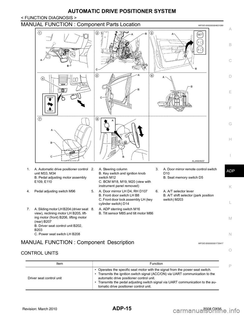
MANUAL FUNCTION : Component Parts LocationINFOID:0000000004831089
MANUAL FUNCTION : Component DescriptionINFOID:0000000001735417
CONTROL UNITS
ALJIA0235ZZ
1. A. Automatic drive positioner control unit M33, M34
B. Pedal adjusting motor assembly
E109, E110 2. A. Steering column
B. Key switch and ignition knob
switch M12
C. BCM M18, M19, M20 (view with
instrument panel removed) 3. A. Door mirror remo
te control switch
D10
B. Seat memory switch D5
4. Pedal adjusting switch M96 5 . A. Door mirrror LH D4, RH D107
B. Front door switch LH B8
C. Front door lock assembly LH (key
cylinder switch) D14 6. A. A/T selector lever
B. A/T shift selector (park position
switch) M203
7. A. Sliding motor LH B204 (driver seat view), reclining motor LH B205, lift-
ing motor (front) B2 06, lifting motor
(rear) B207
B. Driver seat control unit B202,
B203
C. Power seat switch LH B208 8. A. ADP sterring switch M16
B. Tilt sensor M85 and tilt motor M86
Item Function
Driver seat control unit • Operates the specific seat motor with the signal from the power seat switch.
• Transmits the ignition switch signal (ACC/ON) via UART communication to the
automatic drive positioner control unit.
• Transmits the pedal adjusting switch signal via UART communication to the au- tomatic drive positioner control unit.
Revision: March 2010 2008 QX56
Page 33 of 4083

AUTOMATIC DRIVE POSITIONER SYSTEMADP-19
< FUNCTION DIAGNOSIS >
C
DE
F
G H
I
K L
M A
B
ADP
N
O P
MEMORY FUNCTION : Component DescriptionINFOID:0000000001735421
CONTROL UNITS
INPUT PARTS
Switches
Sensors
OUTPUT PARTS
1. A. Automatic drive positioner control unit M33, M34
B. Pedal adjusting motor assembly
E109, E110 2. A. Steering column
B. Key switch and ignition knob
switch M12
C. BCM M18, M19, M20 (view with
instrument panel removed) 3. A. Door mirror remo
te control switch
D10
B. Seat memory switch D5
4. Pedal adjusting switch M96 5 . A. Door mirrror LH D4, RH D107
B. Front door switch LH B8
C. Front door lock assembly LH (key
cylinder switch) D14 6. A. A/T selector lever
B. A/T shift selector (park position
switch) M203
7. A. Sliding motor LH B204 (driver seat view), reclining motor LH B205, lift-
ing motor (front) B2 06, lifting motor
(rear) B207
B. Driver seat control unit B202,
B203
C. Power seat switch LH B208 8. A. ADP sterring switch M16
B. Tilt sensor M85 and tilt motor M86
Item Function
Driver seat control unit • The address of each part is recorded.
• Operates each motor of seat to the registered position.
• Requests the operations of pedal assembly and door mirror to automatic drive po-
sitioner control unit
Automatic drive positioner control unit Operates the pedal adjusting motor, tilt motor and door mirror with the instructions
from the driver seat control.
Item
Function
Memory switch 1/2 The registration and memory function can be performed with its operation.
Item Function
Door mirror sensor (LH/RH) Detect the up/down and left/right position of outside mirror face.
Pedal adjusting sensor Detect the forward/backward position of pedal assembly.
Tilt sensor Detect the upward/downward position of steering wheel.
Lifting sensor (front) Detect the up/down position of seat lifting (front).
Lifting sensor (rear) Detect the up/down position of seat lifting (rear).
Reclining sensor Detect the tilt of seatback.
Sliding sensor Detect the front/rear position of seat.
Item Function
Door mirror motor (LH/RH) Move the outside mirror face upward/downward and leftward/rightward.
Pedal adjusting motor Move the pedal assembly forward/backward.
Tilt motor Move the steering wheel upward/downward.
Lifting motor (front) Move the seat lifter (front) upward/downward.
Lifting motor (rear) Move the seat lifter (rear) upward/downward.
Reclining motor Tilt and raise up the seatback.
Revision: March 2010 2008 QX56
Page 36 of 4083

ADP-22
< FUNCTION DIAGNOSIS >
AUTOMATIC DRIVE POSITIONER SYSTEM
EXIT ASSIST FUNCTION : Component Description
INFOID:0000000001735425
CONTROL UNITS
INPUT PARTS
Switches
Sensors
OUTPUT PARTS
ENTRY ASSIST FUNCTION
1. A. Automatic drive positioner control unit M33, M34
B. Pedal adjusting motor assembly
E109, E110 2. A. Steering column
B. Key switch and ignition knob
switch M12
C. BCM M18, M19, M20 (view with
instrument panel removed) 3. A. Door mirror remo
te control switch
D10
B. Seat memory switch D5
4. Pedal adjusting switch M96 5 . A. Door mirrror LH D4, RH D107
B. Front door switch LH B8
C. Front door lock assembly LH (key
cylinder switch) D14 6. A. A/T selector lever
B. A/T shift selector (park position
switch) M203
7. A. Sliding motor LH B204 (driver seat
view), reclining motor LH B205, lift-
ing motor (front) B206, lifting motor
(rear) B207
B. Driver seat control unit B202,
B203
C. Power seat switch LH B208 8. A. ADP sterring switch M16
B. Tilt sensor M85 and tilt motor M86
Item Function
Driver seat control unit • Operates the seat sliding motor for a constant amount.
• Driver seat control unit requests the operation of the tilt motor to the automatic
drive positioner control unit via UART communication.
Automatic drive positioner control unit Operates the tilt motor for a constant amount.
BCM Recognizes the following status and transmits it to the driver seat control unit via
CAN communication.
• Front door LH: OPEN/CLOSE
Item
Function
Front door switch LH Detect front door LH open/close status.
Item Function
Sliding sensor Detect the front/rear position of seat.
Tilt sensor Detect the up/down position of steering wheel.
Item Function
Sliding motor Slide the seat forward/backward.
Tilt motor Moves the steering wheel upward/downward.
Revision: March 2010 2008 QX56
Page 38 of 4083

ADP-24
< FUNCTION DIAGNOSIS >
AUTOMATIC DRIVE POSITIONER SYSTEM
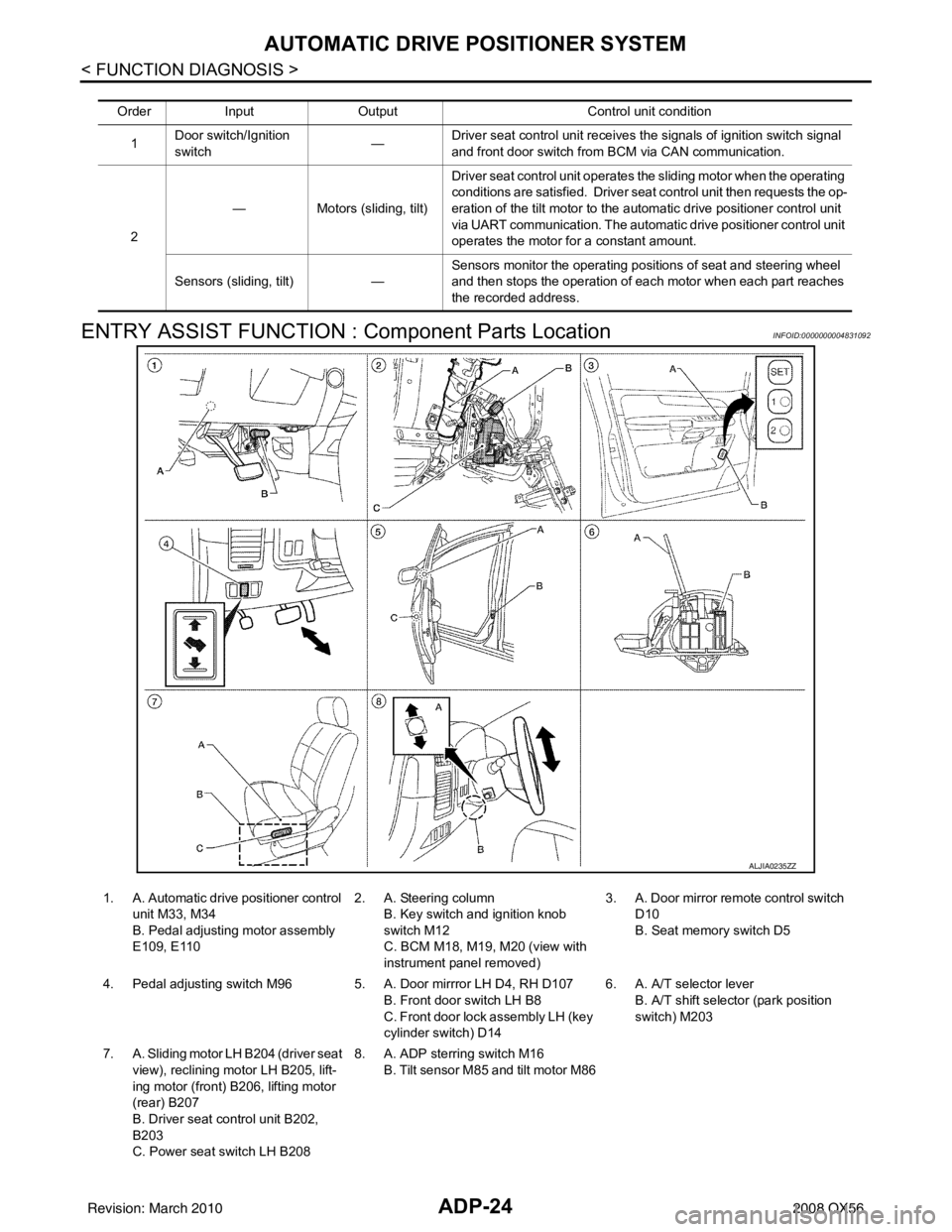
ENTRY ASSIST FUNCTION : Component Parts Location
INFOID:0000000004831092
Order Input Output Control unit condition
1 Door switch/Ignition
switch —
Driver seat control unit receives the signals of ignition switch signal
and front door switch from BCM via CAN communication.
2 —
Motors (sliding, tilt) Driver seat control unit operates the sliding motor when the operating
conditions are satisfied. Driver seat control unit then requests the op-
eration of the tilt motor to the automatic drive positioner control unit
via UART communication. The automatic drive positioner control unit
operates the motor for a constant amount.
Sensors (sliding, tilt) —Sensors monitor the operating positions of seat and steering wheel
and then stops the operation of each motor when each part reaches
the recorded address.
ALJIA0235ZZ
1. A. Automatic drive positioner control
unit M33, M34
B. Pedal adjusting motor assembly
E109, E110 2. A. Steering column
B. Key switch and ignition knob
switch M12
C. BCM M18, M19, M20 (view with
instrument panel removed) 3. A. Door mirror remo
te control switch
D10
B. Seat memory switch D5
4. Pedal adjusting switch M96 5 . A. Door mirrror LH D4, RH D107
B. Front door switch LH B8
C. Front door lock assembly LH (key
cylinder switch) D14 6. A. A/T selector lever
B. A/T shift selector (park position
switch) M203
7. A. Sliding motor LH B204 (driver seat
view), reclining motor LH B205, lift-
ing motor (front) B206, lifting motor
(rear) B207
B. Driver seat control unit B202,
B203
C. Power seat switch LH B208 8. A. ADP sterring switch M16
B. Tilt sensor M85 and tilt motor M86
Revision: March 2010 2008 QX56
Page 70 of 4083

ADP-56
< COMPONENT DIAGNOSIS >
PEDAL ADJUSTING SWITCH
PEDAL ADJUSTING SWITCH
DescriptionINFOID:0000000001735483
Pedal adjusting switch is on the instrument panel. The operation signal is input to the driver seat control unit
when the pedal adjusting switch is operated. The pedal adjus ting switch signal is sent to the automatic drive
positioner control unit via UART communication.
Component Function CheckINFOID:0000000001735484
1. CHECK FUNCTION
1. Select “PEDAL SW-FR”, “PEDAL SW-RR” in “Data monitor” mode with CONSULT-III.
2. Check pedal adjusting switch signal under the following conditions.
Is the indication normal?
YES >> INSPECTION END
NO >> Perform diagnosis procedure. Refer to ADP-56, "
DiagnosisProcedure".
Diagnosis ProcedureINFOID:0000000001735485
1. CHECK PEDAL ADJUSTING SWITCH SIGNAL
1. Turn ignition switch ON.
2. Check voltage between driver seat control unit harness connec- tor and ground.
Is the inspection result normal?
YES >> GO TO 5
NO >> GO TO 2
2. CHECK PEDAL ADJUSTING SWITCH CIRCUIT
Monitor item ConditionStatus
PEDAL SW-FR Pedal adjusting switch (forward) Operate
ON
Release OFF
PEDAL SW-RR Pedal adjusting switch (backward) Operate
ON
Release OFF
Driver seat
control unit connector Te r m i n a l s
ConditionVoltage (V)
(Approx.)
(+) (–)
B202 15
Ground Pedal ad-
justing switch Operate
(backward) 0
Release Battery
voltage
30 Operate
(forward) 0
Release Battery
voltage
PIIA4591E
Revision: March 2010 2008 QX56
Page 193 of 4083
![INFINITI QX56 2008 Factory Service Manual AV-12
< FUNCTION DIAGNOSIS >[AUDIO SYSTEM]
AUDIO SYSTEM
Component Description
INFOID:0000000001696021
10. Rear audio and remote control unit R204 11. Microphone R109 12. Front door speaker
LH D12
RH INFINITI QX56 2008 Factory Service Manual AV-12
< FUNCTION DIAGNOSIS >[AUDIO SYSTEM]
AUDIO SYSTEM
Component Description
INFOID:0000000001696021
10. Rear audio and remote control unit R204 11. Microphone R109 12. Front door speaker
LH D12
RH](/img/42/57030/w960_57030-192.png)
AV-12
< FUNCTION DIAGNOSIS >[AUDIO SYSTEM]
AUDIO SYSTEM
Component Description
INFOID:0000000001696021
10. Rear audio and remote control unit R204 11. Microphone R109 12. Front door speaker
LH D12
RH D112
13. Rear door tweeter LH D208
RH D308 14. Rear door speaker
LH D207
RH D307 15. Back door speaker
LH D518
RH D716
16. Subwoofer B72 (under driver’s seat) 17. BOSE speaker amp M112, M113 (view behind instrument panel above
accelerator pedal)18. Rear camera control unit B73 (locat-
ed behind luggage finisher LHl)
19. Rear view camera D504
Part name Description
AV control unit Controls audio system, NAVI functions and satellite radio system functions
Display unit • Touch screen controls all audio and A/C operations
• Displays all audio and climate control related information
BOSE speaker amp. Receives power (amp ON) and audio signals from AV control unit and out-
puts audio signals to each speaker.
Steering switches • Audio operation can be operated
• Steering switch signal is output to AV control unit
Front door speakers • Outputs audio signal from BOSE speaker amp.
• Outputs high, mid and low range sounds
Front tweeters • Outputs audio signal from BOSE speaker amp.
• Outputs high range sounds
Center speaker • Outputs audio signal from BOSE speaker amp.
• Outputs high range sounds
Rear door speakers • Outputs audio signal from BOSE speaker amp.
• Outputs high, mid and low range sounds
Rear door tweeters • Outputs audio signal from BOSE speaker amp.
• Outputs high range sounds
Back door speakers • Outputs audio signal from BOSE speaker amp.
• Outputs high, mid and low range sounds
Subwoofer • Outputs audio signal from BOSE speaker amp.
• Outputs low range sounds
Satellite antenna Audio signal (satellite radio) is received and output to AV control unit.
Revision: March 2010 2008 QX56
Page 335 of 4083
![INFINITI QX56 2008 Factory Service Manual AV-154
< SYMPTOM DIAGNOSIS >[AUDIO SYSTEM]
NORMAL OPERATING CONDITION
Destination, Passing Points and Menu Items Cannot be Selected/Set
Symptom
Cause Remedy
Map screen and BIRDVIEW™
Name of the pla INFINITI QX56 2008 Factory Service Manual AV-154
< SYMPTOM DIAGNOSIS >[AUDIO SYSTEM]
NORMAL OPERATING CONDITION
Destination, Passing Points and Menu Items Cannot be Selected/Set
Symptom
Cause Remedy
Map screen and BIRDVIEW™
Name of the pla](/img/42/57030/w960_57030-334.png)
AV-154
< SYMPTOM DIAGNOSIS >[AUDIO SYSTEM]
NORMAL OPERATING CONDITION
Destination, Passing Points and Menu Items Cannot be Selected/Set
Symptom
Cause Remedy
Map screen and BIRDVIEW™
Name of the place vary with the
screen. Some thinning of the character data is done to pre-
vent the display becoming to complex. In some
cases and in some locations, the display contents
may differ.
The same place name, street name, etc. may not
be displayed every time on account of the data
processing. System is not malfunctioning.
Vehicle mark is not positioned cor-
rectly. Vehicle is transferred by ferry or by towing after its
ignition switch is turned to OFF. Drive the vehicle for a while in the GPS sat-
ellite signal receiving condition.
Screen will not switch to nighttime
mode after the lighting switch is
turned ON. The daytime screen is selected by the “SWITCH
SCREENS” when the last time the screen dim-
ming setting is done.
Switching between daytime/nighttime screen may
be inhibited by the automatic illumination adjust-
ment function. Perform screen dimming and select the
nighttime screen by “SWITCH SCREENS”.
Map screen will not scroll in accor-
dance with the vehicle travel. Current location is not displayed.
Press “MAP” button to display the current lo-
cation.
Vehicle mark will not be shown. Current location is not displayed. Press “MAP” button to display the current lo-
cation.
Accuracy indicator (GPS satellite
mark) on the map screen stays
gray. GPS satellite signal is intercepted because the ve-
hicle is in or behind a building.
Move the vehicle out to an open space.
GPS satellite signal cannot be received because
an obstacle is placed on top of the instrument pan-
el. Do not place anything on top of the meter dis-
play (instrument panel).
GPS satellites are not visible from current location. Wait until GPS satellites are visible by mov- ing the vehicle.
Vehicle location accuracy is low. Accuracy indicator (GPS sate llite mark) on the
map screen stays gray. Current location is not determined.
Vehicle speed setting by the vehicle speed pulse
has been deviated (advanced or retarded) from
the actual vehicle speed because tire chain is fit-
ted or the system has been used on another vehi-
cle. Drive the vehicle for a while [for approx. 30
minutes at approx. 30 km/h (19 MPH)] and
the deviation will be automatically adjusted. If
advancement or retard still occur, perform
the distance adjustment by CONFIRMA-
TION/ADJUSTMENT mode of diagnosis
function.
Map data has error or omission. (Vehicle mark is
always deviated to the same position.) As a rule, an updated map DVD–ROM will be
released once a year.
Symptom
Cause Remedy
Destination cannot be set. Destination to be set is on an expressway. Set the destination on an ordinary road.
Passing point is not searched
when re-searching the route. The vehicle has already passed the passing point,
or the system judged so. To include the passing points that have been
passed into the route again, set the route
again.
Route information will not be dis-
played. Route searching has not been done.
Set the destination and perform route
searching.
Vehicle mark is not on the recommended route. Drive on the recommended route.
Route guide is turned OFF. Turn route guide ON.
Route information is not available on the dark pink
route. System is not malfunctioning.
After the route searching, no guide
sign will appear as the vehicle
goes near the entrance/exit to the
toll road. Vehicle mark is not on the recommended route.
(On the display, only guide signs related to the rec-
ommended route will be shown.)
Drive on the recommended route.
Revision: March 2010
2008 QX56
Page 347 of 4083
![INFINITI QX56 2008 Factory Service Manual AV-166
< ON-VEHICLE REPAIR >[AUDIO SYSTEM]
DISPLAY UNIT
DISPLAY UNIT
Removal and InstallationINFOID:0000000001601492
REMOVAL
1. Remove cluster lid C. Refer to
IP-15, "Removal and Installation".
2. Re INFINITI QX56 2008 Factory Service Manual AV-166
< ON-VEHICLE REPAIR >[AUDIO SYSTEM]
DISPLAY UNIT
DISPLAY UNIT
Removal and InstallationINFOID:0000000001601492
REMOVAL
1. Remove cluster lid C. Refer to
IP-15, "Removal and Installation".
2. Re](/img/42/57030/w960_57030-346.png)
AV-166
< ON-VEHICLE REPAIR >[AUDIO SYSTEM]
DISPLAY UNIT
DISPLAY UNIT
Removal and InstallationINFOID:0000000001601492
REMOVAL
1. Remove cluster lid C. Refer to
IP-15, "Removal and Installation".
2. Remove the display unit screws (A), pull out the display unit (1) from instrument panel, to disconnect the display unit connectors.
3. Remove the A/C auto amp. screws (A) and the A/C auto amp. (1).
• Display unit (2)
4. Remove the display unit bracket screws and the display unit brackets.
INSTALLATION
Installation is in the reverse order of removal.
ALNIA0272ZZ
ALIIA0063ZZ
Revision: March 2010 2008 QX56