wiring diagram INFINITI QX56 2009 Factory Service Manual
[x] Cancel search | Manufacturer: INFINITI, Model Year: 2009, Model line: QX56, Model: INFINITI QX56 2009Pages: 4171, PDF Size: 84.65 MB
Page 2241 of 4171

CONSULT-III CHECKING SYSTEMGI-47
< BASIC INSPECTION >
C
DE
F
G H
I
J
K L
M B
GI
N
O P
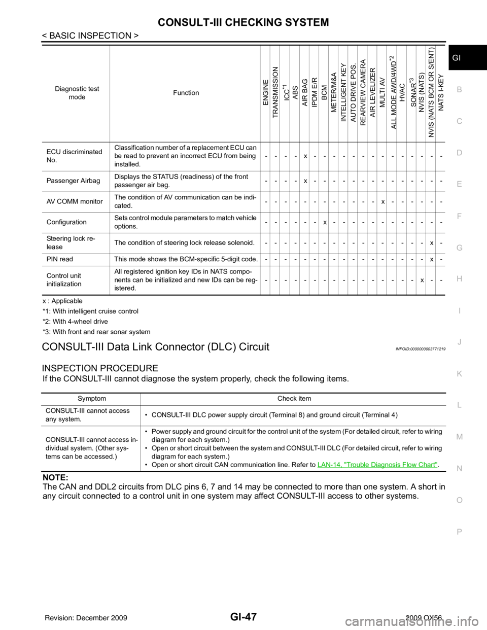
x : Applicable
*1: With intelligent cruise control
*2: With 4-wheel drive
*3: With front and rear sonar system
CONSULT-III Data Link Connector (DLC) CircuitINFOID:0000000003771219
INSPECTION PROCEDURE
If the CONSULT-III cannot diagnose the sys tem properly, check the following items.
NOTE:
The CAN and DDL2 circuits from DLC pins 6, 7 and 14 may be connected to more than one system. A short in
any circuit connected to a control unit in one system may affect CONSULT-III access to other systems.
ECU discriminated
No.Classification number of a replacement ECU can
be read to prevent an incorrect ECU from being
installed.
----x--------------
Passenger Airbag Displays the STATUS (readiness) of the front
passenger air bag.
----x--------------
AV COMM monitor The condition of AV communication can be indi-
cated. ------------x------
Configuration Sets control module para
meters to match vehicle
options. ------x------------
Steering lock re-
lease The condition of steering lock release solenoid. -----------------x-
PIN read This mode shows the BCM-specific 5-digit code.-----------------x-
Control unit
initialization All registered ignition key IDs in NATS compo-
nents can be initialized and new IDs can be reg-
istered.
----------------x--
Diagnostic test
mode Function
ENGINE
TRANSMISSION
ICC
*1
ABS
AIR BAG
IPDM E/R BCM
METER/M&A
INTELLIGENT KEY
AUTO DRIVE POS.
REARVIEW CAMERA AIR LEVELIZER
MULTI AV
ALL MODE AWD/4WD
*2
HVAC
SONAR
*3
NVIS (NATS)
NVIS (NATS BCM OR S/ENT) NATS I-KEY
Symptom Check item
CONSULT-III cannot access
any system. • CONSULT-III DLC power supply circuit (Terminal 8) and ground circuit (Terminal 4)
CONSULT-III cannot access in-
dividual system. (Other sys-
tems can be accessed.) • Power supply and ground circuit for the control unit of the system (For detailed circuit, refer to wiring
diagram for each system.)
• Open or short circuit between the system and CONSULT-III DLC (For detailed circuit, refer to wiring diagram for each system.)
• Open or short circuit CAN communication line. Refer to LAN-14, "
Trouble Diagnosis Flow Chart".
Revision: December 20092009 QX56
Page 2242 of 4171

GI-48
< BASIC INSPECTION >
CONSULT-III CHECKING SYSTEM
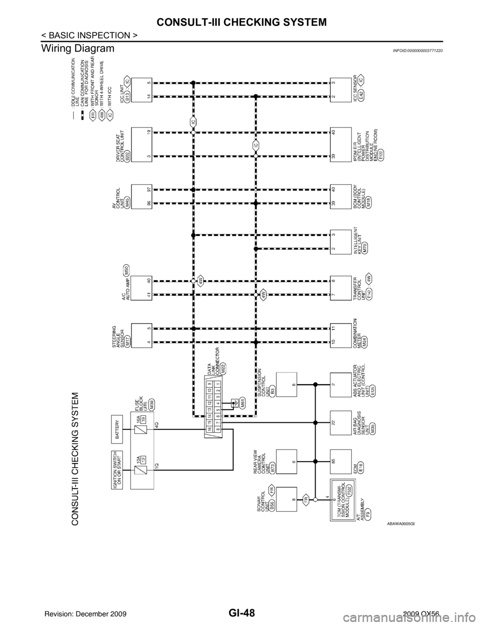
Wiring Diagram
INFOID:0000000003771220
ABAWA0005GB
Revision: December 20092009 QX56
Page 2315 of 4171

HAC-2
MAGNET CLUTCH ............................................72
System Description .............................................. ...72
Magnet Clutch Component Function Check ........ ...72
Magnet Clutch Diagnosis Procedure ................... ...73
WATER VALVE CIRCUIT ..................................77
Description ........................................................... ...77
Water Valve Diagnosis Procedure ..........................77
AMBIENT SENSOR ...........................................79
Component Description ....................................... ...79
Ambient Sensor Diagnosis Procedure ....................79
Ambient Sensor Component Inspection .................80
IN-VEHICLE SENSOR .......................................82
Component Description ....................................... ...82
In-Vehicle Sensor Diagnosis Procedure .................82
In-Vehicle Sensor Component Inspection ..............84
OPTICAL SENSOR ...........................................85
Component Description ..........................................85
Optical Sensor Diagnosis Procedure ......................85
INTAKE SENSOR ..............................................87
System Description .............................................. ...87
Intake Sensor Diagnosis Procedure .......................87
Intake Sensor Component Inspection ................. ...88
POWER SUPPLY AND GROUND CIRCUIT
FOR CONTROLLER ..........................................
89
Component Description ....................................... ...89
A/C Auto Amp. Component Function Check ..........89
A/C Auto Amp Power and Ground Diagnosis Pro-
cedure .....................................................................
90
ECU DIAGNOSIS .......................................91
AIR CONDITIONER CONTROL ..................... ...91
A/C Auto Amp. Terminals Reference Values ..........91
Wiring Diagram .................................................... ...93
SYMPTOM DIAGNOSIS ...........................109
AIR CONDITIONER CONTROL ..................... ..109
Symptom Matrix Chart ........................................ .109
INSUFFICIENT COOLING ................................110
Component Function Check ................................ .110
Diagnostic Work Flow ...........................................111
Performance Chart ................................................113
Trouble Diagnoses for Abnormal Pressure ...........114
INSUFFICIENT HEATING ................................118
Component Function Check .................................118
NOISE ...............................................................120
Component Function Check ................................ .120
MEMORY FUNCTION DOES NOT OPERATE ..122
Memory Function Check ...................................... .122
PRECAUTION ...........................................123
PRECAUTIONS .............................................. ..123
Precaution for Supplemental Restraint System
(SRS) "AIR BAG" and "SEAT BELT PRE-TEN-
SIONER" .............................................................. .
123
Working with HFC-134a (R-134a) ........................ .123
Precaution for Service Equipment ........................124
Revision: December 20092009 QX56
Page 2406 of 4171
![INFINITI QX56 2009 Factory Service Manual AIR CONDITIONER CONTROLHAC-93
< ECU DIAGNOSIS > [AUTOMATIC AIR CONDITIONER]
C
D
E
F
G H
J
K L
M A
B
HAC
N
O P
Wiring DiagramINFOID:0000000003775389
ABIWA0010GB
Revision: December 20092009 QX56 INFINITI QX56 2009 Factory Service Manual AIR CONDITIONER CONTROLHAC-93
< ECU DIAGNOSIS > [AUTOMATIC AIR CONDITIONER]
C
D
E
F
G H
J
K L
M A
B
HAC
N
O P
Wiring DiagramINFOID:0000000003775389
ABIWA0010GB
Revision: December 20092009 QX56](/img/42/57031/w960_57031-2405.png)
AIR CONDITIONER CONTROLHAC-93
< ECU DIAGNOSIS > [AUTOMATIC AIR CONDITIONER]
C
D
E
F
G H
J
K L
M A
B
HAC
N
O P
Wiring DiagramINFOID:0000000003775389
ABIWA0010GB
Revision: December 20092009 QX56
Page 2438 of 4171

HRN-1
DRIVER CONTROLS
C
DE
F
G H
I
J
K
M
SECTION HRN
A
B
HRN
N
O P
CONTENTS
HORN
PRECAUTION ....... ........................................2
PRECAUTIONS .............................................. .....2
Precaution for Supplemental Restraint System
(SRS) "AIR BAG" and "SEAT BELT PRE-TEN-
SIONER" ............................................................. ......
2
Precaution Necessary for Steering Wheel Rota-
tion After Battery Disconnect ............................... ......
2
COMPONENT DIAGNOSIS ..........................4
HORN .................................................................4
Wiring Diagram .................................................... .....4
REMOVAL AND INSTALLATION ................7
HORN .................................................................7
Removal and Installation ..................................... .....7
Revision: December 20092009 QX56
Page 2441 of 4171

HRN-4
< COMPONENT DIAGNOSIS >
HORN
COMPONENT DIAGNOSIS
HORN
Wiring DiagramINFOID:0000000003776367
ABLWA0062GB
Revision: December 20092009 QX56
Page 2445 of 4171

INL-1
DRIVER CONTROLS
C
DE
F
G H
I
J
K
M
SECTION INL
A
B
INL
N
O P
CONTENTS
INTERIOR LIGHTING SYSTEM
BASIC INSPECTION ....... .............................3
DIAGNOSIS AND REPAIR WORKFLOW ..... .....3
Work Flow ........................................................... ......3
FUNCTION DIAGNOSIS ...............................6
INTERIOR ROOM LAMP CONTROL SYSTEM
.....
6
System Diagram .................................................. ......6
System Description ...................................................6
Component Parts Location ........................................7
Component Description .............................................8
ILLUMINATION CONTROL SYSTEM .................9
System Diagram .................................................. ......9
System Description ...................................................9
Component Parts Location ........................................9
Component Description ...........................................10
DIAGNOSIS SYSTEM (BCM) ............................11
COMMON ITEM ..................................................... ....11
COMMON ITEM : CONSULT-III Function (BCM -
COMMON ITEM) .....................................................
11
INT LAMP .............................................................. ....11
INT LAMP : CONSULT-III Function (BCM - INT
LAMP) .....................................................................
12
BATTERY SAVER ................................................. ....13
BATTERY SAVER : CONSULT-III Function (BCM
- BATTERY SAVER) ...............................................
13
COMPONENT DIAGNOSIS .........................14
POWER SUPPLY AND GROUND CIRCUIT .. ....14
BCM ....................................................................... ....14
BCM : Diagnosis Procedure ....................................14
BATTERY SAVER OUTPUT/POWER SUP-
PLY CIRCUIT ................................................. ....
15
Description ........................................................... ....15
Component Function Check ....................................15
Diagnosis Procedure ...............................................15
INTERIOR ROOM LAMP CONTROL CIRCUIT
...
17
Description ........................................................... ....17
Component Function Check ....................................17
Diagnosis Procedure ...............................................17
STEP LAMP CIRCUIT .......................................19
Description ........................................................... ....19
Component Function Check ....................................19
Diagnosis Procedure ...............................................19
CARGO LAMP CONTROL CIRCUIT ................21
Description ...............................................................21
Component Function Check ....................................21
Diagnosis Procedure ...............................................21
IGNITION KEYHOLE ILLUMINATION CON-
TROL CIRCUIT .................................................
23
Description ...............................................................23
Component Function Check ....................................23
Diagnosis Procedure ...............................................23
INTERIOR ROOM LAMP CONTROL SYSTEM
...
25
Wiring Diagram .................................................... ....25
ILLUMINATION .................................................41
Wiring Diagram ........................................................41
ECU DIAGNOSIS .........................................55
BCM (BODY CONTROL MODULE) .................55
Reference Value .................................................. ....55
Terminal Layout .......................................................57
Physical Values ................................................... ....57
Wiring Diagram ........................................................63
Fail Safe ..................................................................67
DTC Inspection Priority Chart ...............................68
Revision: December 20092009 QX56
Page 2469 of 4171

INTERIOR ROOM LAMP CONTROL SYSTEMINL-25
< COMPONENT DIAGNOSIS >
C
DE
F
G H
I
J
K
M A
B
INL
N
O P
INTERIOR ROOM LAMP CONTROL SYSTEM
Wiring DiagramINFOID:0000000003776266
ABLWA0043GB
Revision: December 20092009 QX56
Page 2485 of 4171

ILLUMINATIONINL-41
< COMPONENT DIAGNOSIS >
C
DE
F
G H
I
J
K
M A
B
INL
N
O P
ILLUMINATION
Wiring DiagramINFOID:0000000003776267
ABLWA0046GB
Revision: December 20092009 QX56
Page 2507 of 4171

BCM (BODY CONTROL MODULE)INL-63
< ECU DIAGNOSIS >
C
DE
F
G H
I
J
K
M A
B
INL
N
O P
Wiring DiagramINFOID:0000000004109554
AAMWA0236GB
Revision: December 20092009 QX56