torque INFINITI QX56 2009 Factory Service Manual
[x] Cancel search | Manufacturer: INFINITI, Model Year: 2009, Model line: QX56, Model: INFINITI QX56 2009Pages: 4171, PDF Size: 84.65 MB
Page 3880 of 4171
TM-232
< DISASSEMBLY AND ASSEMBLY >
DISASSEMBLY
DISASSEMBLY
DisassemblyINFOID:0000000004187489
CAUTION:
Do not disassemble parts behind Drum Support. Refer to TM-8, "Cross-Sectional View (2WD models)"
.
1. Drain A/T fluid through drain plug.
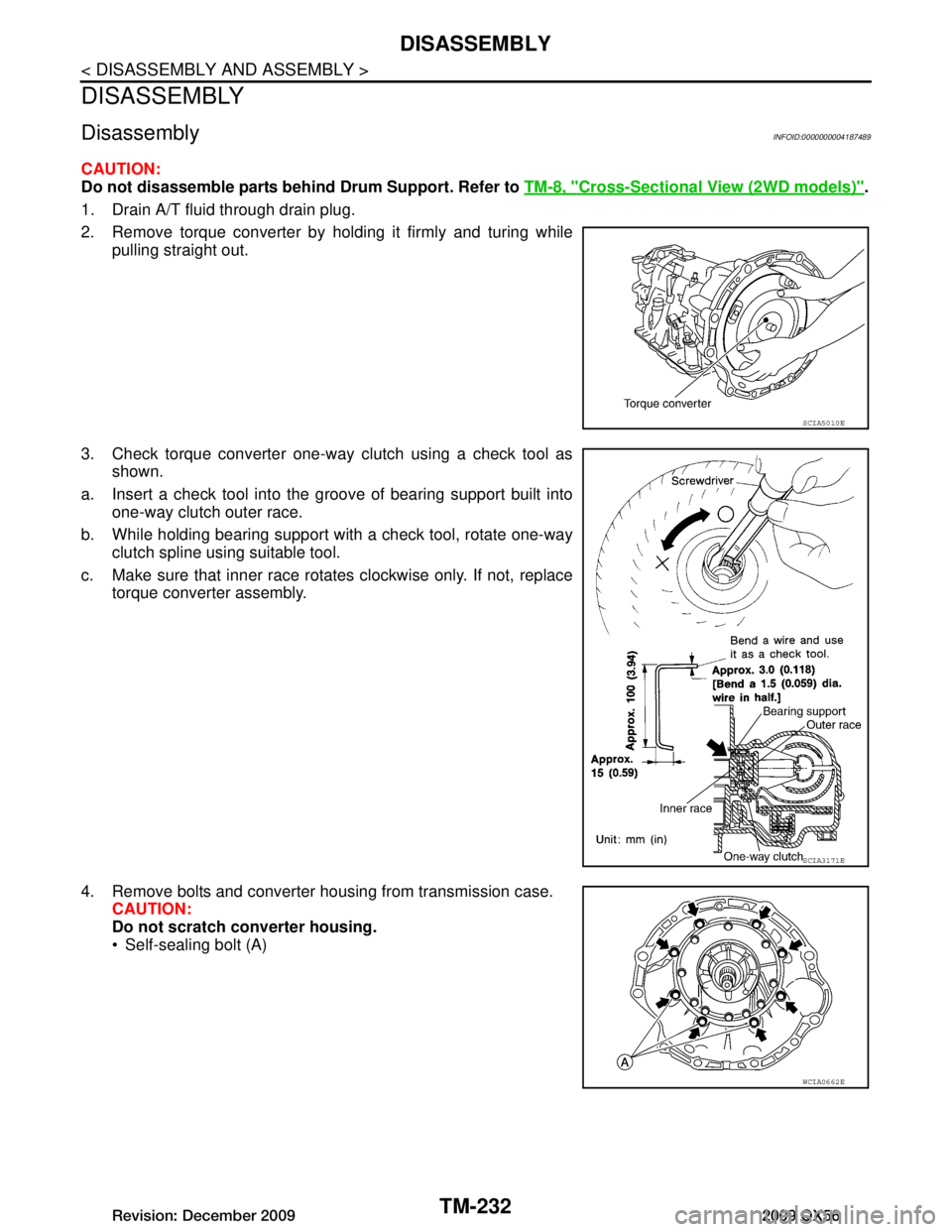
2. Remove torque converter by holding it firmly and turing while pulling straight out.
3. Check torque converter one-way clutch using a check tool as shown.
a. Insert a check tool into the groove of bearing support built into one-way clutch outer race.
b. While holding bearing support with a check tool, rotate one-way clutch spline using suitable tool.
c. Make sure that inner race rotates clockwise only. If not, replace torque converter assembly.
4. Remove bolts and converter housing from transmission case. CAUTION:
Do not scratch converter housing.
Self-sealing bolt (A)
SCIA5010E
SCIA3171E
WCIA0662E
Revision: December 20092009 QX56
Page 3899 of 4171
REPAIR FOR COMPONENT PARTSTM-251
< DISASSEMBLY AND ASSEMBLY >
CEF
G H
I
J
K L
M A
B
TM
N
O P
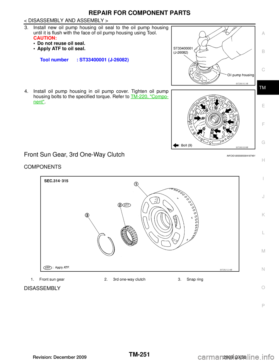
3. Install new oil pump housing oil seal to the oil pump housing until it is flush with the face of oil pump housing using Tool.
CAUTION:
Do not reuse oil seal.
Apply ATF to oil seal.
4. Install oil pump housing in oil pump cover. Tighten oil pump housing bolts to the specified torque. Refer to TM-220, "Compo-
nent".
Front Sun Gear, 3rd One-Way ClutchINFOID:0000000004187491
COMPONENTS
DISASSEMBLY
Tool number : ST33400001 (J-26082)
SCIA5313E
SCIA5228E
1. Front sun gear 2. 3rd one-way clutch 3. Snap ring
SCIA3114E
Revision: December 20092009 QX56
Page 3921 of 4171
ASSEMBLYTM-273
< DISASSEMBLY AND ASSEMBLY >
CEF
G H
I
J
K L
M A
B
TM
N
O P
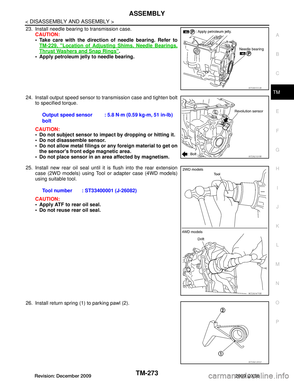
23. Install needle bearing to transmission case. CAUTION:
Take care with the direction of needle bearing. Refer toTM-229, "Location of Adjusting Shims, Needle Bearings,
Thrust Washers and Snap Rings".
Apply petroleum jelly to needle bearing.
24. Install output speed sensor to transmission case and tighten bolt to specified torque.
CAUTION:
Do not subject sensor to impact by dropping or hitting it.
Do not disassemble sensor.
Do not allow metal filings or any foreign material to get on
the sensor's front edge magnetic area.
Do not place sensor in an area affected by magnetism.
25. Install new rear oil seal until it is flush into the rear extension case (2WD models) using Tool or adapter case (4WD models)
using suitable tool.
CAUTION:
Apply ATF to rear oil seal.
Do not reuse rear oil seal.
26. Install return spring (1) to parking pawl (2).
SCIA5031E
Output speed sensor
bolt : 5.8 N·m (0.59 kg-m, 51 in-lb)
SCIA2320E
Tool number : ST33400001 (J-26082)
WCIA0475E
SCIA6180J
Revision: December 20092009 QX56
Page 3924 of 4171
TM-276
< DISASSEMBLY AND ASSEMBLY >
ASSEMBLY
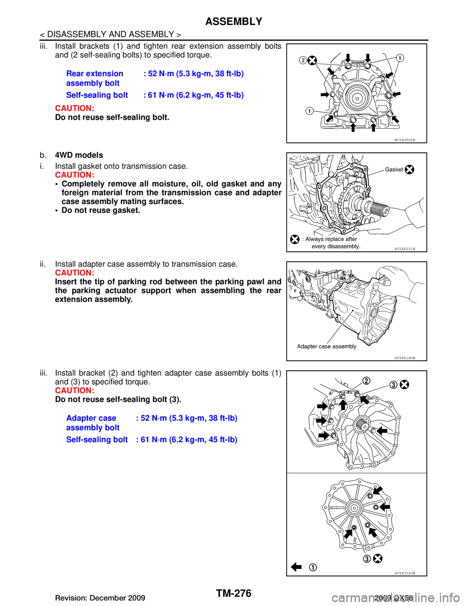
iii. Install brackets (1) and tighten rear extension assembly boltsand (2 self-sealing bolts) to specified torque.
CAUTION:
Do not reuse self-sealing bolt.
b. 4WD models
i. Install gasket onto transmission case. CAUTION:
Completely remove all moistu re, oil, old gasket and any
foreign material from the transmission case and adapter
case assembly mating surfaces.
Do not reuse gasket.
ii. Install adapter case assembly to transmission case. CAUTION:
Insert the tip of parking rod between the parking pawl and
the parking actuator support when assembling the rear
extension assembly.
iii. Install bracket (2) and tighten adapter case assembly bolts (1) and (3) to specified torque.
CAUTION:
Do not reuse self-sealing bolt (3).Rear extension
assembly bolt
: 52 N·m (5.3 kg-m, 38 ft-lb)
Self-sealing bolt : 61 N·m (6.2 kg-m, 45 ft-lb)
WCIA0562E
SCIA5231E
SCIA5186E
Adapter case
assembly bolt : 52 N·m (5.3 kg-m, 38 ft-lb)
Self-sealing bolt : 61 N·m (6.2 kg-m, 45 ft-lb)
SCIA7220E
Revision: December 20092009 QX56
Page 3929 of 4171
ASSEMBLYTM-281
< DISASSEMBLY AND ASSEMBLY >
CEF
G H
I
J
K L
M A
B
TM
N
O P
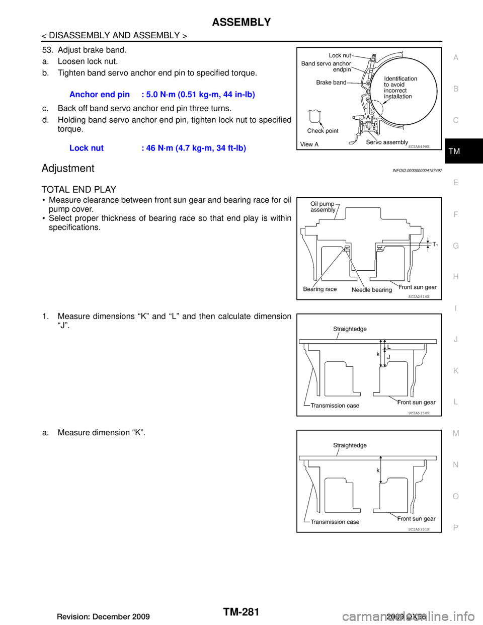
53. Adjust brake band.
a. Loosen lock nut.
b. Tighten band servo anchor end pin to specified torque.
c. Back off band servo anchor end pin three turns.
d. Holding band servo anchor end pin, tighten lock nut to specified torque.
AdjustmentINFOID:0000000004187497
TOTAL END PLAY
Measure clearance between front sun gear and bearing race for oilpump cover.
Select proper thickness of bearing race so that end play is within specifications.
1. Measure dimensions “K” and “L” and then calculate dimension “J”.
a. Measure dimension “K”. Anchor end pin : 5.0 N·m (0.51 kg-m, 44 in-lb)
Lock nut : 46 N·m (4.7 kg-m, 34 ft-lb)
SCIA5498E
SCIA2810E
SCIA5350E
SCIA5351E
Revision: December 20092009 QX56
Page 3932 of 4171
TM-284
< DISASSEMBLY AND ASSEMBLY >
ASSEMBLY
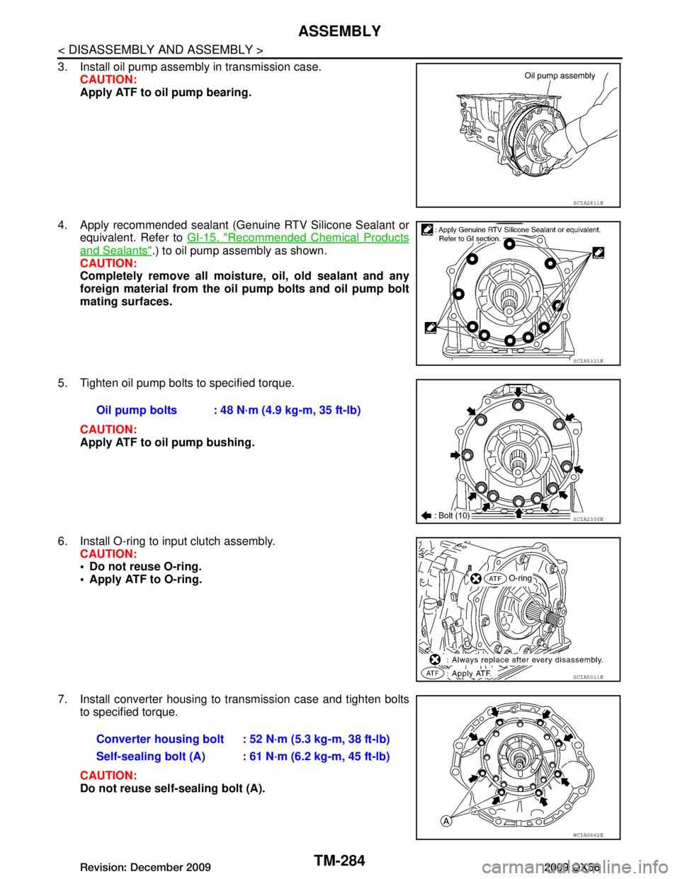
3. Install oil pump assembly in transmission case.CAUTION:
Apply ATF to oil pump bearing.
4. Apply recommended sealant (Genuine RTV Silicone Sealant or equivalent. Refer to GI-15, "Recommended Chemical Products
and Sealants".) to oil pump assembly as shown.
CAUTION:
Completely remove all moistu re, oil, old sealant and any
foreign material from the oil pump bolts and oil pump bolt
mating surfaces.
5. Tighten oil pump bolts to specified torque. CAUTION:
Apply ATF to oil pump bushing.
6. Install O-ring to input clutch assembly. CAUTION:
Do not reuse O-ring.
Apply ATF to O-ring.
7. Install converter housing to transmission case and tighten bolts to specified torque.
CAUTION:
Do not reuse self-sealing bolt (A).
SCIA2811E
SCIA5321E
Oil pump bolts : 48 N·m (4.9 kg-m, 35 ft-lb)
SCIA2300E
SCIA5011E
Converter housing bolt : 52 N·m (5.3 kg-m, 38 ft-lb)
Self-sealing bolt (A) : 61 N·m (6.2 kg-m, 45 ft-lb)
WCIA0662E
Revision: December 20092009 QX56
Page 3934 of 4171

TM-286
< DISASSEMBLY AND ASSEMBLY >
ASSEMBLY
e. Install A/T fluid temperature sensor 2 to bracket.
f. Install A/T fluid temperature sensor 2 (with bracket) to controlvalve with TCM and tighten bolt to specified torque.
CAUTION:
Adjust bolt hole of bracket to bolt hole of control valve.
g. Install control valve with TCM in transmission case. 1. : Brake band
CAUTION:
Make sure that input speed sensor is securely installed
into input speed sensor hole (A).
Hang down output speed sen sor harness toward outside
so as not to disturb installati on of control valve with TCM.
Adjust A/T assembly harness co nnector of control valve
with TCM to terminal hole of transmission case.
Assemble it so that manual valve cutout is engaged with manual plate projection.
SCIA5264E
Bracket bolt : 7.9 N·m (0.81 kg-m, 70 in-lb)
SCIA5253E
JSDIA1318ZZ
SCIA5035E
Revision: December 20092009 QX56
Page 3935 of 4171

ASSEMBLYTM-287
< DISASSEMBLY AND ASSEMBLY >
CEF
G H
I
J
K L
M A
B
TM
N
O P
h. Install bolts (A), (B) and (C) to control valve with TCM. : Front
i. Tighten bolt (A), (B) and (C) temporarily to prevent dislocation. After that tighten them in order (A → B → C), and then tighten
other bolts.
: Front
10. Connect A/T fluid temperature sensor 2 connector (A).
11. Securely fasten terminal cord assembly and A/T fluid tempera- ture sensor 2 harness with terminal clips.
12. Connect output speed sensor connector (1).
13. Securely fasten output speed sensor harness with terminal clip.
14. Pull down A/T assembly harness connector. CAUTION:
Do not damage connector.
Bolt symbol Length mm (in) Number of bolts
A 42 (1.65) 5
B 55 (2.17) 6
C 40 (1.57) 1
SCIA8077E
Bolt symbol A B C
Number of bolts 5 6 1
Length mm (in) 42 (1.65) 55 (2.17) 40 (1.57)
Tightening torque
N·m (km-g, in-lb) 7.9 (0.81, 70)With ATF applied
7.9 (0.81, 70)
SCIA8078E
SCIA8124E
JSDIA1319ZZ
SCIA5299E
Revision: December 20092009 QX56
Page 3936 of 4171
TM-288
< DISASSEMBLY AND ASSEMBLY >
ASSEMBLY
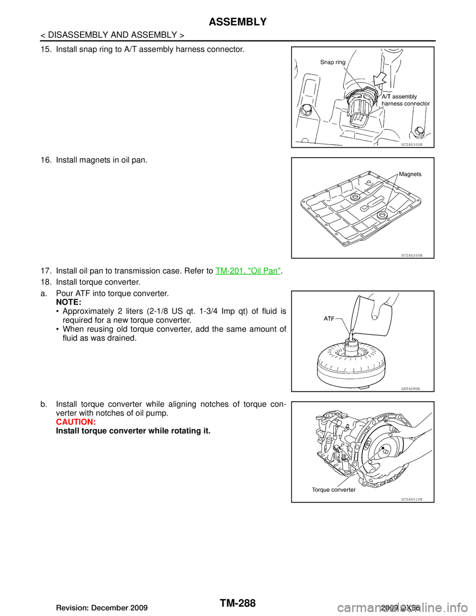
15. Install snap ring to A/T assembly harness connector.
16. Install magnets in oil pan.
17. Install oil pan to transmission case. Refer to TM-201, "Oil Pan"
.
18. Install torque converter.
a. Pour ATF into torque converter. NOTE:
Approximately 2 liters (2-1/8 US qt. 1-3/4 Imp qt) of fluid is
required for a new torque converter.
When reusing old torque converter, add the same amount of
fluid as was drained.
b. Install torque converter while aligning notches of torque con- verter with notches of oil pump.
CAUTION:
Install torque converte r while rotating it.
SCIA5300E
SCIA5200E
SAT428DA
SCIA5010E
Revision: December 20092009 QX56
Page 3937 of 4171
ASSEMBLYTM-289
< DISASSEMBLY AND ASSEMBLY >
CEF
G H
I
J
K L
M A
B
TM
N
O P
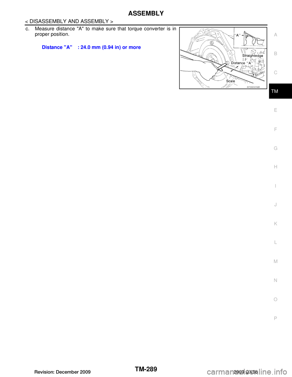
c. Measure distance "A" to make sure that torque converter is in proper position.
Distance "A" : 24.0 mm (0.94 in) or more
SCIA5694E
Revision: December 20092009 QX56