horn INFINITI QX56 2009 Factory Repair Manual
[x] Cancel search | Manufacturer: INFINITI, Model Year: 2009, Model line: QX56, Model: INFINITI QX56 2009Pages: 4171, PDF Size: 84.65 MB
Page 3427 of 4171

SN
INSPECTION AND ADJUSTMENTSN-5
< BASIC INSPECTION >
C
DE
F
G H
I
J
K L
M B A
O P
INSPECTION AND ADJUSTMENT
Preliminary CheckINFOID:0000000003776738
DESCRIPTION
The purpose of the sonar sensor preliminary check is to confirm that there are no outside factors affecting the
sonar system.
CONDITIONS
• Ignition switch ON
• No obstructions within 3.0 m (10 ft.) of sonar sensors
SONAR SENSOR STATUS CHECK
• Check that the sonar sensors are properly aligned (no deformation in sensor mounting areas).
• Check that snow, mud or other foreign obj ects are not adhering to the sonar sensors.
• Check that there is no deformation, scratc hes or other damage to the sonar sensors.
• Check that water has not accu mulated in the sonar sensors.
CAUTION:
Use water, cotton swab, or other soft material for cleaning the sensors.
1. Check that there are no obstacles wit hin each sonar sensor's detection range.
2. Check that there are no nearby ultrasound sources such as the sounds of vehicle horns, motorcycle
engines or truck air brakes.
3. Check that the vehicle is on a level surface.
Sonar sensors Detection range
Front Approx. 1.0 m (3 ft.) maximum
Rear Approx. 1.8 m (5.9 ft.) maximum
Revision: December 20092009 QX56
Page 3478 of 4171

DRIVER AIR BAG MODULESR-5
< ON-VEHICLE REPAIR >
C
DE
F
G
I
J
K L
M A
B
SR
N
O P
ON-VEHICLE REPAIR
DRIVER AIR BAG MODULE
Removal and InstallationINFOID:0000000003775157
REMOVAL
CAUTION:
• Do not attempt to repair or replace damaged direct-connect SRS component connectors. If a driver air bag direct-connect harness connector is damaged, the spiral cable must be replaced.
• Before servicing the SRS, turn ignition switch OFF, disconnect both battery terminals and wait at
least three minutes.
• When servicing the SRS, do not work from directly in front of air bag module.
1. Disconnect both the negative and positive battery te rminals, then wait at least three minutes.
2. Remove the left and right side bolts.
3. Lift the driver air bag module from the steering wheel.
4. Disconnect the air bag harness and horn connectors, then remove the driver air bag module. • For removal/installation of the direct-connect SRS connectors, refer to SRC-9, "
Direct-connect SRS
Component Connectors".
CAUTION:
• When servicing the SRS, do not work from directly in front of air bag module.
• Always place air bag module wi th pad side facing upward.
• Do not insert any foreign object s (screwdriver, etc.) into air
bag module or harness connectors.
• Do not disassemble air bag module.
• Do not use old bolts after removal; replace with new bolts.
• Do not expose the air bag mo dule to temperatures exceeding
90° C (194 °F).
1. Horn harness 2. Steering wheel hook3. Inflator harness
4. Side lids RH/LH 5. Driver air bag module6. Steering wheel
WHIA0159E
LHIA0052E
Revision: December 20092009 QX56
Page 4100 of 4171
DIAGNOSIS SYSTEM (IPDM E/R)WW-13
< FUNCTION DIAGNOSIS >
C
DE
F
G H
I
J
K
M A
B
WW
N
O P
DIAGNOSIS SYSTEM (IPDM E/R)
Diagnosis DescriptionINFOID:0000000004115472
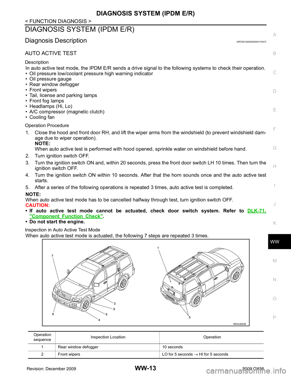
AUTO ACTIVE TEST
Description
In auto active test mode, the IPDM E/R sends a drive signal to the following systems to check their operation.
• Oil pressure low/coolant pressure high warning indicator
• Oil pressure gauge
• Rear window defogger
• Front wipers
• Tail, license and parking lamps
• Front fog lamps
• Headlamps (Hi, Lo)
• A/C compressor (magnetic clutch)
• Cooling fan
Operation Procedure
1. Close the hood and front door RH, and lift the wiper arms from the windshield (to prevent windshield dam-
age due to wiper operation).
NOTE:
When auto active test is performed with hood opened, sprinkle water on windshield before hand.
2. Turn ignition switch OFF.
3. Turn the ignition switch ON and, within 20 seconds, press the front door switch LH 10 times. Then turn the ignition switch OFF.
4. Turn the ignition switch ON within 10 seconds. Af ter that the horn sounds once and the auto active test
starts.
5. After a series of the following operations is repeated 3 times, auto active test is completed.
NOTE:
When auto active test mode has to be cancelled halfway through test, turn ignition switch OFF.
CAUTION:
• If auto active test mode cannot be actua ted, check door switch system. Refer to DLK-71,
"ComponentFunctionCheck".
• Do not start the engine.
Inspection in Auto Active Test Mode
When auto active test mode is actuated, the following 7 steps are repeated 3 times.
Operation
sequence Inspection Location
Operation
1 Rear window defogger 10 seconds
2 Front wipers LO for 5 seconds → HI for 5 seconds
WKIA4655E
Revision: December 20092009 QX56
Page 4103 of 4171
![INFINITI QX56 2009 Factory Repair Manual WW-16
< FUNCTION DIAGNOSIS >
DIAGNOSIS SYSTEM (IPDM E/R)
ACTIVE TEST
Te s t i t e m
Monitor Item[Unit] MAIN SIG-
NALS Description
MOTOR FAN REQ
[1/2/3/4] ×Displays the status of the cooling fan spee](/img/42/57031/w960_57031-4102.png "INFINITI QX56 2009 Factory Repair Manual WW-16
< FUNCTION DIAGNOSIS >
DIAGNOSIS SYSTEM (IPDM E/R)
ACTIVE TEST
Te s t i t e m
Monitor Item[Unit] MAIN SIG-
NALS Description
MOTOR FAN REQ
[1/2/3/4] ×Displays the status of the cooling fan spee")
WW-16
< FUNCTION DIAGNOSIS >
DIAGNOSIS SYSTEM (IPDM E/R)
ACTIVE TEST
Te s t i t e m
Monitor Item[Unit] MAIN SIG-
NALS Description
MOTOR FAN REQ
[1/2/3/4] ×Displays the status of the cooling fan speed request signal received from ECM via
CAN communication.
A/C COMP REQ
[OFF/ON] ×Displays the status of the A/C request signal received from AV control unit via
CAN communication.
TA I L & C L R R E Q
[OFF/ON] ×
Displays the status of the position light request signal received from BCM via CAN
communication.
HL LO REQ
[OFF/ON] ×Displays the status of the low beam request signal received from BCM via CAN
communication.
HL HI REQ
[OFF/ON] ×Displays the status of the high beam request signal received from BCM via CAN
communication.
FR FOG REQ
[OFF/ON] ×
Displays the status of the front fog lamp request signal received from BCM via
CAN communication.
HL WASHER REQ
[OFF/ON] NOTE:
This item is displayed, but cannot be monitored.
FR WIP REQ
[STOP/1LOW/LOW/HI] ×Displays the status of the front wiper request signal received from BCM via CAN
communication.
WIP AUTO STOP
[STOP P/ACT P] ×
Displays the status of the front wiper auto stop signal judged by IPDM E/R.
WIP PROT
[OFF/Block] ×
Displays the status of the front wiper fail-safe operation judged by IPDM E/R.
ST RLY REQ
[OFF/ON] Displays the status of the starter request signal received from ECM via CAN com-
munication.
IGN RLY
[OFF/ON] ×
Displays the status of the ignition relay judged by IPDM E/R.
RR DEF REQ
[OFF/ON] ×Displays the status of the rear defogger request signal received from AV control
unit via CAN communication.
OIL P SW
[OPEN/CLOSE] Displays the status of the oil pressure switch judged by IPDM E/R.
DTRL REQ
[OFF] NOTE:
This item is displayed, but cannot be monitored.
HOOD SW
[OPEN/CLOSE] Displays the status of the hood switch judged by IPDM E/R.
THFT HRN REQ
[OFF/ON] Displays the status of the theft warning horn request signal received from BCM
via CAN communication.
HORN CHIRP
[OFF/ON] Displays the status of the horn reminder signal received from BCM via CAN com-
munication.
Test item
Operation Description
REAR DEFOGGER OFF
OFF
ON Operates rear window defogger relay.
FRONT WIPER OFF
OFF
LO Operates the front wiper relay.
HI Operates the front wiper relay and front wiper high relay.
MOTOR FAN 1O
FF
2O FF
3 Operates the cooling fan relay.
4 Operates the cooling fan relay.
Revision: December 20092009 QX56
Page 4104 of 4171

DIAGNOSIS SYSTEM (IPDM E/R)WW-17
< FUNCTION DIAGNOSIS >
C
DE
F
G H
I
J
K
M A
B
WW
N
O P
EXTERNAL LAMPS OFF
OFF
TAIL Operates the tail lamp relay.
LO Operates the headlamp low relay.
HI Operates the headlamp low relay and the headlamp high LH/RH relays at 1 sec-
ond intervals.
FOG Operates the front fog lamp relay
HORN ONOperates horn relay for 20 ms.
Test item
Operation Description
Revision: December 20092009 QX56
Page 4142 of 4171

IPDM E/R (INTELLIGENT POWER DISTRIBUTION MODULE ENGINE ROOM)
WW-55
< ECU DIAGNOSIS >
C
D E
F
G H
I
J
K
M A
B
WW
N
O P
THFT HRN REQ Not operated
OFF
• Panic alarm is activated
• Horn is activated with VEHICLE SECURITY (THEFT WARNING) SYS-
TEM ON
HORN CHIRP Not operated
OFF
Door locking with Intelligent Key (horn chirp mode) ON
Monitor Item
ConditionValue/Status
Revision: December 20092009 QX56
Page 4146 of 4171

IPDM E/R (INTELLIGENT POWER DISTRIBUTION MODULE ENGINE ROOM)
WW-59
< ECU DIAGNOSIS >
C
D E
F
G H
I
J
K
M A
B
WW
N
O P
41 Y/B Hood switch Input —Hood closed OFF
0V
Hood open ON Battery voltage
42 GR Oil pressure switch Input — Engine running
Battery voltage
Engine stopped 0V
43 L/Y Wiper auto stop signal Input ON or
START Wiper switch OFF, LO, INT Battery voltage
44 BR Daytime light relay
control Input ONDaytime light system active
0V
Daytime light system inactive Battery voltage
45 G/W Horn relay control Input ON When door locks are operated
using keyfob or Intelligent Key
(OFF
→ ON)* Battery voltage
→ 0V
46 GR Fuel pump relay con-
trol
Input —Ignition switch ON or START
0V
Ignition switch OFF or ACC Battery voltage
47 O Throttle control motor
relay control
Input —Ignition switch ON or START
0V
Ignition switch OFF or ACC Battery voltage
48 B/R Starter relay (inhibit
switch) InputON or
START Selector lever in "P" or "N"
0V
Selector lever any other posi-
tion Battery voltage
49 R/L Trailer tow relay Output ON Lighting
switch must
be in the 1st
positionOFF
0V
ON Battery voltage
50 W/R Front fog lamp (LH) Output ON or
START Lighting
switch must
be in the 2nd
position
(LOW beam
is ON) and
the front fog
lamp switch OFF
0V
ON Battery voltage
51 W/R Front fog lamp (RH) Output ON or
START Lighting
switch must
be in the 2nd
position
(LOW beam
is ON) and
the front fog
lamp switch OFF
0V
ON Battery voltage
52 L LH low beam head-
lamp Output — Lighting switch in 2nd position Battery voltage
54 R/Y RH low beam head-
lamp Output — Lighting switch in 2nd position Battery voltage
55 G LH high beam head-
lamp Output —Lighting switch in 2nd position
and placed in HIGH or PASS
position Battery voltage
56 L/W RH high beam head-
lamp Output —Lighting switch in 2nd position
and placed in HIGH or PASS
position Battery voltage
57 R/L Parking, license, and
tail lamp
Output ONLighting
swi
t
ch 1st po-
sition OFF
0V
ON Battery voltage
Te r m i n a l
Wire
color Signal name Signal
input/
output Measuring condition
Reference value(Approx.)
Igni-
tion
switch Operation or condition
Revision: December 20092009 QX56
Page 4147 of 4171

WW-60
< ECU DIAGNOSIS >
IPDM E/R (INTELLIGENT POWER DISTRIBUTION MODULE ENGINE ROOM)
*: When horn reminder is ON59 B Ground Input — — 0V
60 B/W
Rear window defog-
ger relay
OutputON or
START Rear defogger switch ON
Battery voltage
Rear defogger switch OFF 0V
61 BR Fuse 32 Output OFF—Battery voltage
Te r m i n a l
Wire
color Signal name Signal
input/
output Measuring condition
Reference value(Approx.)
Igni-
tion
switch Operation or condition
Revision: December 20092009 QX56