ABS INFINITI QX56 2010 Factory Service Manual
[x] Cancel search | Manufacturer: INFINITI, Model Year: 2010, Model line: QX56, Model: INFINITI QX56 2010Pages: 4210, PDF Size: 81.91 MB
Page 3203 of 4210

RSU-16
< REMOVAL AND INSTALLATION >
SHOCK ABSORBER
2. Drill 2 – 3 mm (0.08 – 0.12 in) hole at the position ( ) from topas shown in the figure to release gas gradually.
CAUTION:
• Wear eye protection (safety glasses).
• Wear gloves.
• Be careful with metal chips or oil blown out by the com-pressed gas.
NOTE:
• Drill vertically in this direction ( ).
• Directly to the outer tube avoiding brackets.
• The gas is clear, colorless, odorless, and harmless.
3. Position the drilled hole downward and drain oil by moving the piston rod several times. CAUTION:
Dispose of drained oil according to the law and local regulations.
A : 20 – 30 mm (0.79 – 1.18 in)
JPEIA0161ZZ
Revision: April 20092010 QX56
Page 3204 of 4210

SUSPENSION ARMRSU-17
< REMOVAL AND INSTALLATION >
C
DF
G H
I
J
K L
M A
B
RSU
N
O P
SUSPENSION ARM
Removal and InstallationINFOID:0000000005148134
REMOVAL
1. Remove the rear suspension member assembly using power tool. Refer to RSU-11, "Removal and Instal-
lation" .
NOTE:
It is necessary to remove the rear suspension member to remove the front upper bolt from the suspension
arm.
2. Remove the shock absorber upper end bolt.
3. Remove the suspension arm upper nuts and bolts on the sus- pension member side using power tool.
4. Remove the suspension arm pinch bolt and nut on the knuckle side using power tool.
5. Disconnect the suspension arm from the knuckle using a soft hammer.
CAUTION:
Do not damage the ball joint with the soft hammer.
6. Remove the suspension arm.
INSPECTION AFTER REMOVAL
• Check the suspension arm for damage, cracks, deformation and replace if necessary.
• Check the rubber bushing for damage, cracks and deformati on. Replace suspension arm assembly if neces-
sary.
• Before checking, turn the ball joint at least 10 revo lutions so that the ball joint is properly broken in.
LEIA0082E
LEIA0087E
Revision: April 20092010 QX56
Page 3206 of 4210

FRONT LOWER LINKRSU-19
< REMOVAL AND INSTALLATION >
C
DF
G H
I
J
K L
M A
B
RSU
N
O P
FRONT LOWER LINK
Removal and InstallationINFOID:0000000005148135
REMOVAL
1. Remove the wheel and tire assembly using power tool.
2. Use CONSULT-III "EXHAUST SOLENOID" active test to release the air pressure from the rear load level-
ing air suspension system.
3. Remove the shock absorber lower end bolt.
4. Remove the adjusting bolt and nut, and the bolt and nut, from the front lower link and rear suspension member using power
tool.
5. Remove the front lower link pinch bolt and nut on the knuckle side using power tool.
6. Disconnect the front lower link from the knuckle using a soft hammer.
CAUTION:
Do not damage the ball joint with the soft hammer.
7. Remove the front lower link.
INSPECTION AFTER REMOVAL
• Check the front lower link and bushing for any deforma tion, crack, or damage. Replace if necessary.
• Check the rubber bushing for damage, cracks and deforma tion. Replace the front lower link and bushing if
necessary.
• Before checking, turn the ball joint at least 10 revo lutions so that the ball joint is properly broken in.
LEIA0082E
LEIA0086E
Revision: April 20092010 QX56
Page 3211 of 4210

RSU-24
< REMOVAL AND INSTALLATION >
REAR LOAD LEVELING AIR SUSPENSION COMPRESSOR ASSEMBLY
REAR LOAD LEVELING AIR SUSPENSION COMPRESSOR ASSEMBLY
Removal and InstallationINFOID:0000000005148138
Rear Load Leveling Air Suspension System
REMOVAL
1. Use CONSULT-III "EXHAUST SOLENOID" active test to release the air pressure from the rear load level-
ing air suspension system.
2. Disconnect the electrical connectors for the rear load leveling air suspension compressor assembly.
3. Unclip the rubber cover to access the rear load leveling air suspension compressor assembly.
4. Disconnect the rear load leveling air suspension hoses at the rear load leveling air suspension compressor assembly.
• To disconnect the hoses, push in on the lock ring using a suit-
able tool and pull the hose out.
AWEIA0054GB
1. Rear load leveling air suspension
hose, RH 2. Shock absorber, RH
3. Height sensor
4. Rear load leveling air suspension hose, LH 5. Shock absorber, LH
6. Rear load leveling air suspension
compressor assembly
Front
LEIA0074E
Revision: April 20092010 QX56
Page 3214 of 4210

HEIGHT SENSORRSU-27
< REMOVAL AND INSTALLATION >
C
DF
G H
I
J
K L
M A
B
RSU
N
O P
HEIGHT SENSOR
Removal and InstallationINFOID:0000000005148141
Rear Load Leveling Air Suspension System
REMOVAL
1. Use CONSULT-III “EXHAUST SOLENOID ” active test to release the air pressure from the rear load level-
ing air suspension system.
2. Disconnect the electrical connector for the height sensor.
3. Remove the two height sensor bolts and height sensor arm bracket bolt.
4. Remove the height sensor.
INSTALLATION
Installation is in the reverse order of removal.
AWEIA0054GB
1. Rear load leveling air suspension hose, RH 2. Shock absorber, RH 3. Height sensor
4. Rear load leveling air suspension hose, LH 5. Shock absorber, LH
6. Rear load leveling air suspension
compressor assembly
Front
LEIA0080E
Revision: April 20092010 QX56
Page 3341 of 4210

FRONT SEATSE-69
< DISASSEMBLY AND ASSEMBLY >
C
DE
F
G H
I
K L
M A
B
SE
N
O P
Disassembly and AssemblyINFOID:0000000005256345
SEATBACK TRIM AND PAD
Disassembly
CAUTION:
• Only complete seatback assemblies can be replaced on vehicles equipped with side air bags.
• When removing or installing the seat trim, handle it carefully to keep dirt out and avoid damage.
1. Remove the seatback assembly. Refer to SE-51, "
Removal and Installation".
2. Remove the headrest.
3. From inside of the seatback, squeeze the headrest holder tabs
at the base of the stay pipe and pull the up to remove.
NOTE:
Before installing the headrest holder, check its orientation (front/
rear and right/left).
4. Remove the snap ring and the lumbar support lever knob (if equipped).
5. Remove the seatback trim and pad assembly.
6. Remove the hog rings to separate the seatback trim from the pad.
Assembly
Assembly is in the reverse order of disassembly.
SEAT CUSHION TRIM AND PAD
Disassembly
CAUTION:
• Front passenger seat is equipped with an Occupant Classification System sensor and control mod-
ule. Do not disassemble front passenger seat cushion assembly or remove the trim as this will affect
the Occupant Classificatio n System calibration.
• Always replace passenger seat cushion as an assembly.
• When removed, the passenger seat cushion must al ways be placed pan side UP to prevent damage.
• During installation, the wire harness clips must be reinstalled in the holes they were originally in. Do
not add additional clips.
• The Occupant Classification System control module can only be replaced as part of the seat cushion
assembly.
19. Outer pedestal finisher 20. Seat cushion outer finisher21. Seat cushion assembly
22. Power seat switch escutcheon 23. Slide switch knob 24. Recliner switch knob
25. Seatback assembly 26. Headrest holder27. Seat slide/ recline switch
28. Power lumbar switch
LRS023
PIIA1156E
Revision: April 20092010 QX56
Page 3342 of 4210

SE-70
< DISASSEMBLY AND ASSEMBLY >
FRONT SEAT
1. Remove the recline release lever.
2. Remove four bolts and the seat cushion assembly. • On the fold flat passenger seat it is necessary to unclip the
rear flap j-clip from the seat pan.
3. On the drivers seat only, remove the seat cushion trim and pad.
4. On the drivers seat only, remove the hog rings to separate the trim cover from the pad.
Assembly
Assembly is in the reverse order of disassembly.
PASSENGER SEATBACK BOARD - SOFT SEATBACK
Removal
1. The seatback board is attached to the seat frame with the follow-
ing:
• 2 top tabs (A)
• 4 side tabs (B)
• 2 bottom clips (C) (must be replaced)
2. Move seat to forward position.
3. Hold the seatback board as show n and pull the top of the seat-
back board away from the seat back frame.
4. Pull the middle part of the seatback board to disengage the side tabs (B) from the seatback frame.
5. Pull the lower part of the seatback board to disengage the bot- tom clips from the seatback frame.
SIIA0503E
ALIIA0394ZZ
ALIIA0368ZZ
ALIIA0367ZZ
Revision: April 20092010 QX56
Page 3343 of 4210

FRONT SEATSE-71
< DISASSEMBLY AND ASSEMBLY >
C
DE
F
G H
I
K L
M A
B
SE
N
O P
Installation
Installation is in the reverse order of removal.
PASSENGER SEATBACK BOARD - HARD SEATBACK
Removal
1. The seatback board is attached to
the seat frame with the follow-
ing:
• 2 top tabs (A)
• 2 side tabs (B)
• 2 bottom clips (C) (must be replaced)
2. Move seat to forward position.
3. Hold the seatback board as shown and pull the bottom of the seatback board away from the seat back frame.
4. Pull the middle part of the seatback board to disengage the side tabs (B) from the seatback frame.
5. Lift the upper part of the seatback board to disengage the top tabs from the seatback frame.
Installation
Installation is in the reverse order of removal.
ALIIA0395ZZ
ALIIA0370ZZ
ALIIA0371ZZ
Revision: April 20092010 QX56
Page 3530 of 4210

SPIRAL CABLESR-7
< ON-VEHICLE REPAIR >
C
DE
F
G
I
J
K L
M A
B
SR
N
O P
SPIRAL CABLE
Removal and InstallationINFOID:0000000005147758
REMOVAL
CAUTION:
• Before servicing the SRS, turn ignition switch OFF, disconnect both battery terminals and wait at
least three minutes.
• When servicing the SRS, do not work from directly in front of air bag module.
1. Disconnect both the negative and positive battery te rminals, then wait at least three minutes.
2. Remove the steering wheel. Refer to ST-18, "
Removal and Installation".
3. Remove the instrument lower panel LH. Refer to IP-14, "
Exploded View".
4. Remove the column cover upper and lower.
5. Remove wiper washer switch connector, then pinch the tabs at wiper and washer switch base and slide switch away from steer-
ing column to remove.
1. Steering wheel 2. Lighting and turn signal switch 3. Wiper and washer switch
4. Spiral cable 5. Driver air bag module connector 6. Column cover upper
7. Column assembly 8. Column cover lower9. Screw (Do not remove)
10. Screw A. Refer to ST-18, "
Removal and Instal-
lation"
AWHIA0141GB
LHIA0034E
Revision: April 20092010 QX56
Page 3531 of 4210
SR-8
< ON-VEHICLE REPAIR >
SPIRAL CABLE
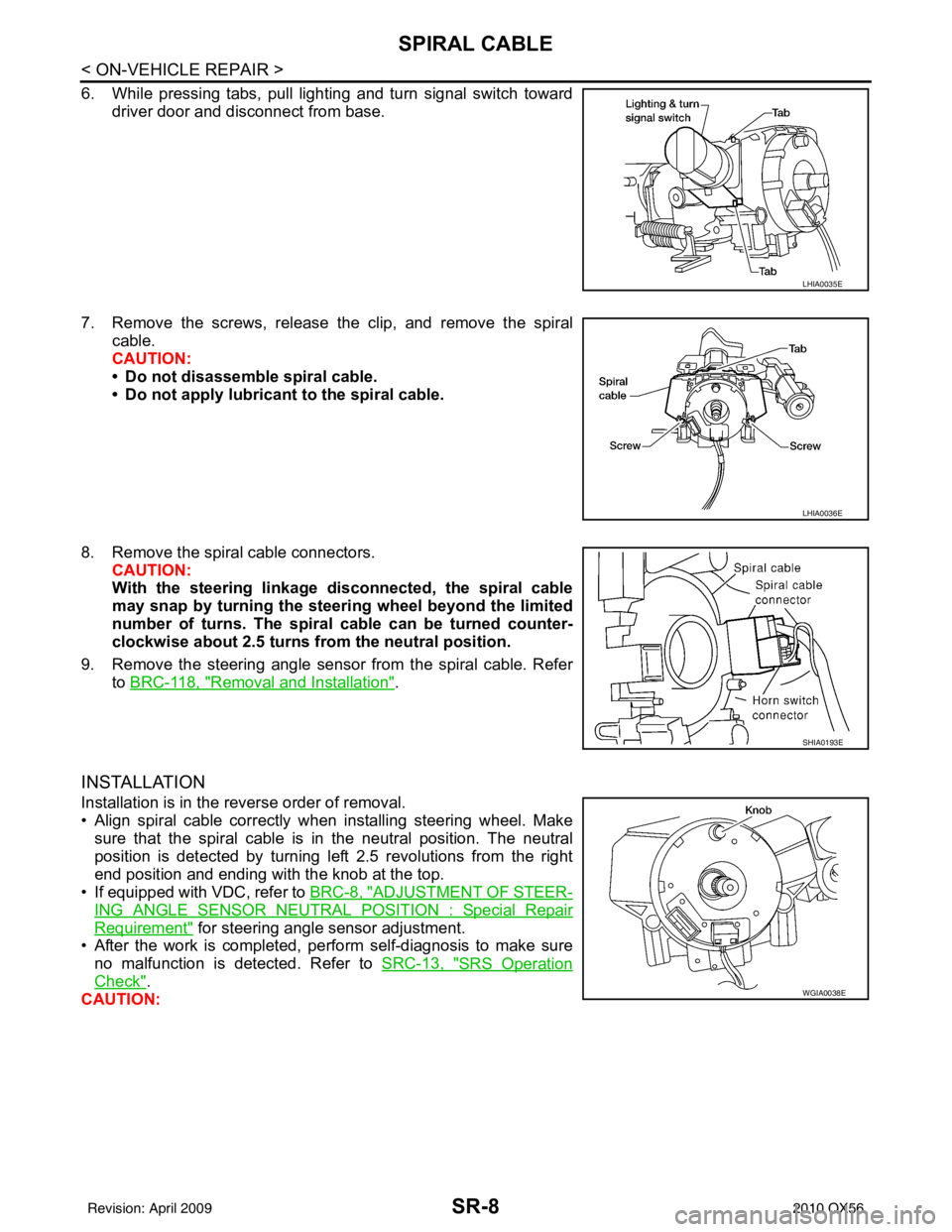
6. While pressing tabs, pull lighting and turn signal switch towarddriver door and disconnect from base.
7. Remove the screws, release the clip, and remove the spiral cable.
CAUTION:
• Do not disassemble spiral cable.
• Do not apply lubricant to the spiral cable.
8. Remove the spiral cable connectors. CAUTION:
With the steering linkage di sconnected, the spiral cable
may snap by turning the steer ing wheel beyond the limited
number of turns. The spiral cable can be turned counter-
clockwise about 2.5 turns fr om the neutral position.
9. Remove the steering angle sensor from the spiral cable. Refer to BRC-118, "
Removal and Installation".
INSTALLATION
Installation is in the reverse order of removal.
• Align spiral cable correctly when installing steering wheel. Make
sure that the spiral cable is in the neutral position. The neutral
position is detected by turning left 2.5 revolutions from the right
end position and ending with the knob at the top.
• If equipped with VDC, refer to BRC-8, "
ADJUSTMENT OF STEER-
ING ANGLE SENSOR NEUTRAL POSITION : Special Repair
Requirement" for steering angle sensor adjustment.
• After the work is completed, perform self-diagnosis to make sure no malfunction is detected. Refer to SRC-13, "
SRS Operation
Check".
CAUTION:
LHIA0035E
LHIA0036E
SHIA0193E
WGIA0038E
Revision: April 20092010 QX56