engine INFINITI QX56 2010 Factory Owner's Manual
[x] Cancel search | Manufacturer: INFINITI, Model Year: 2010, Model line: QX56, Model: INFINITI QX56 2010Pages: 4210, PDF Size: 81.91 MB
Page 440 of 4210
![INFINITI QX56 2010 Factory Owners Manual BCS-54
< ECU DIAGNOSIS >[BCM]
BCM (BODY CONTROL MODULE)
DTC Inspection Priority Chart
INFOID:0000000005146433
If some DTCs are displayed at the same time, perform inspections one by one based on the f INFINITI QX56 2010 Factory Owners Manual BCS-54
< ECU DIAGNOSIS >[BCM]
BCM (BODY CONTROL MODULE)
DTC Inspection Priority Chart
INFOID:0000000005146433
If some DTCs are displayed at the same time, perform inspections one by one based on the f](/img/42/57032/w960_57032-439.png)
BCS-54
< ECU DIAGNOSIS >[BCM]
BCM (BODY CONTROL MODULE)
DTC Inspection Priority Chart
INFOID:0000000005146433
If some DTCs are displayed at the same time, perform inspections one by one based on the following priority
chart.
DTC IndexINFOID:0000000005146434
NOTE: Details of time display
• CRNT: Displays when there is a malfunction now or after returning to the normal condition until turning igni- tion switch OFF → ON again.
• 1 - 39: Displayed if any previous malfunction is present when current condition is normal. It increases like 1
→ 2 → 3...38 → 39 after returning to the normal condition whenever ignition switch OFF → ON. The counter
remains at 39 even if the number of cycles exceeds it. It is counted from 1 again when turning ignition switch
OFF → ON after returning to the normal condition if the malfunction is detected again.
Display contents of CONS ULTFail-safe Cancellation
U1000: CAN COMM CIRCUIT I nhibit engine crankingWhen the BCM re-establishes communication with the other mod-
ules.
Priority
DTC
1 • U1000: CAN COMM CIRCUIT
2 • B2190: NATS ANTENNA AMP
• B2191: DIFFERENCE OF KEY
• B2192: ID DISCORD BCM-ECM
• B2193: CHAIN OF BCM-ECM
• B2013: STRG COMM 1
• B2552: INTELLIGENT KEY
• B2590: NATS MALFUNCTION
3 • C1729: VHCL SPEED SIG ERR
• C1735: IGNITION SIGNAL
4 • C1708: [NO DATA] FL
• C1709: [NO DATA] FR
• C1710: [NO DATA] RR
• C1711: [NO DATA] RL
• C1712: [CHECKSUM ERR] FL
• C1713: [CHECKSUM ERR] FR
• C1714: [CHECKSUM ERR] RR
• C1715: [CHECKSUM ERR] RL
• C1716: [PRESSDATA ERR] FL
• C1717: [PRESSDATA ERR] FR
• C1718: [PRESSDATA ERR] RR
• C1719: [PRESSDATA ERR] RL
• C1720: [CODE ERR] FL
• C1721: [CODE ERR] FR
• C1722: [CODE ERR] RR
• C1723: [CODE ERR] RL
• C1724: [BATT VOLT LOW] FL
• C1725: [BATT VOLT LOW] FR
• C1726: [BATT VOLT LOW] RR
• C1727: [BATT VOLT LOW] RL
CONSULT display
Fail-safeIntelligent Key
warning lamp ON Tire pressure
monitor warning lamp ON Reference page
No DTC is detected.
further testing
may be required. ————
U1000: CAN COMM CIRCUIT ———BCS-32
B2190: NATS ANTENNA AMP ———SEC-31
Revision: April 20092010 QX56
Page 443 of 4210
![INFINITI QX56 2010 Factory Owners Manual BCS
PRECAUTIONSBCS-57
< PRECAUTION > [BCM]
C
D
E
F
G H
I
J
K L
B A
O P
N
PRECAUTION
PRECAUTIONS
Precaution for Supplemental
Restraint System (SRS) "AIR BAG" and "SEAT BELT
PRE-TENSIONER"
INFOID:0000 INFINITI QX56 2010 Factory Owners Manual BCS
PRECAUTIONSBCS-57
< PRECAUTION > [BCM]
C
D
E
F
G H
I
J
K L
B A
O P
N
PRECAUTION
PRECAUTIONS
Precaution for Supplemental
Restraint System (SRS) "AIR BAG" and "SEAT BELT
PRE-TENSIONER"
INFOID:0000](/img/42/57032/w960_57032-442.png)
BCS
PRECAUTIONSBCS-57
< PRECAUTION > [BCM]
C
D
E
F
G H
I
J
K L
B A
O P
N
PRECAUTION
PRECAUTIONS
Precaution for Supplemental
Restraint System (SRS) "AIR BAG" and "SEAT BELT
PRE-TENSIONER"
INFOID:0000000005384312
The Supplemental Restraint System such as “AIR BAG” and “SEAT BELT PRE-TENSIONER”, used along
with a front seat belt, helps to reduce the risk or severi ty of injury to the driver and front passenger for certain
types of collision. This system includes seat belt switch inputs and dual stage front air bag modules. The SRS
system uses the seat belt switches to determine the front air bag deployment, and may only deploy one front
air bag, depending on the severity of a collision and w hether the front occupants are belted or unbelted.
Information necessary to service the system safely is included in the SR and SB section of this Service Man-
ual.
WARNING:
• To avoid rendering the SRS inoper ative, which could increase the risk of personal injury or death in
the event of a collision which would result in air bag inflation, all maintenance must be performed by
an authorized NISSAN/INFINITI dealer.
• Improper maintenance, including in correct removal and installation of the SRS, can lead to personal
injury caused by unintentional act ivation of the system. For removal of Spiral Cable and Air Bag
Module, see the SR section.
• Do not use electrical test equipm ent on any circuit related to the SRS unless instructed to in this
Service Manual. SRS wiring harnesses can be identi fied by yellow and/or orange harnesses or har-
ness connectors.
PRECAUTIONS WHEN USING POWER TOOLS (AIR OR ELECTRIC) AND HAMMERS
WARNING:
• When working near the Airbag Diagnosis Sensor Un it or other Airbag System sensors with the Igni-
tion ON or engine running, DO NOT use air or el ectric power tools or strike near the sensor(s) with a
hammer. Heavy vibration could activate the sensor( s) and deploy the air bag(s), possibly causing
serious injury.
• When using air or electric power tools or hammers, always switch the Ignition OFF, disconnect the battery, and wait at least 3 minutes before performing any service.
Precaution Necessary for Steering Wheel Rotation After Battery Disconnect
INFOID:0000000005282709
NOTE:
• This Procedure is applied only to models with Intelligent Key system and NATS (NISSAN ANTI-THEFT SYS-
TEM).
• Remove and install all control units after disconnecti ng both battery cables with the ignition knob in the
″ LOCK ″ position.
• Always use CONSULT-III to perform self-diagnosis as a part of each function inspection after finishing work.
If DTC is detected, perform trouble diagnosis according to self-diagnostic results.
For models equipped with the Intelligent Key system and NATS , an electrically controlled steering lock mech-
anism is adopted on the key cylinder.
For this reason, if the battery is disconnected or if the battery is discharged, the steering wheel will lock and
steering wheel rotation will become impossible.
If steering wheel rotation is required when battery power is interrupted, follow the procedure below before
starting the repair operation.
OPERATION PROCEDURE
1. Connect both battery cables. NOTE:
Supply power using jumper cables if battery is discharged.
2. Use the Intelligent Key or mechanical key to turn the ignition switch to the ″ACC ″ position. At this time, the
steering lock will be released.
3. Disconnect both battery cables. The steering lock will remain released and the steering wheel can be
rotated.
4. Perform the necessary repair operation.
Revision: April 20092010 QX56
Page 448 of 4210

PRECAUTIONSBR-3
< PRECAUTION >
C
DE
G H
I
J
K L
M A
B
BR
N
O P
PRECAUTION
PRECAUTIONS
Precaution for Supplemental Restraint System (SRS) "AIR BAG" and "SEAT BELT
PRE-TENSIONER"
INFOID:0000000005403123
The Supplemental Restraint System such as “AIR BAG” and “SEAT BELT PRE-TENSIONER”, used along
with a front seat belt, helps to reduce the risk or severi ty of injury to the driver and front passenger for certain
types of collision. This system includes seat belt switch inputs and dual stage front air bag modules. The SRS
system uses the seat belt switches to determine the front air bag deployment, and may only deploy one front
air bag, depending on the severity of a collision and w hether the front occupants are belted or unbelted.
Information necessary to service the system safely is included in the SR and SB section of this Service Man-
ual.
WARNING:
• To avoid rendering the SRS inoper ative, which could increase the risk of personal injury or death in
the event of a collision which would result in air bag inflation, all maintenance must be performed by
an authorized NISSAN/INFINITI dealer.
• Improper maintenance, including in correct removal and installation of the SRS, can lead to personal
injury caused by unintentional act ivation of the system. For removal of Spiral Cable and Air Bag
Module, see the SR section.
• Do not use electrical test equipm ent on any circuit related to the SRS unless instructed to in this
Service Manual. SRS wiring harnesses can be identi fied by yellow and/or orange harnesses or har-
ness connectors.
PRECAUTIONS WHEN USING POWER TOOLS (AIR OR ELECTRIC) AND HAMMERS
WARNING:
• When working near the Airbag Diagnosis Sensor Un it or other Airbag System sensors with the Igni-
tion ON or engine running, DO NOT use air or el ectric power tools or strike near the sensor(s) with a
hammer. Heavy vibration could activate the sensor( s) and deploy the air bag(s), possibly causing
serious injury.
• When using air or electric power tools or hammers, always switch the Ignition OFF, disconnect the battery, and wait at least 3 minutes before performing any service.
Precaution Necessary for Steering Wheel Rotation After Battery Disconnect
INFOID:0000000005403124
NOTE:
• This Procedure is applied only to models with Intelligent Key system and NATS (NISSAN ANTI-THEFT SYS-
TEM).
• Remove and install all control units after disconnecti ng both battery cables with the ignition knob in the
″ LOCK ″ position.
• Always use CONSULT-III to perform self-diagnosis as a part of each function inspection after finishing work.
If DTC is detected, perform trouble diagnosis according to self-diagnostic results.
For models equipped with the Intelligent Key system and NATS , an electrically controlled steering lock mech-
anism is adopted on the key cylinder.
For this reason, if the battery is disconnected or if the battery is discharged, the steering wheel will lock and
steering wheel rotation will become impossible.
If steering wheel rotation is required when battery power is interrupted, follow the procedure below before
starting the repair operation.
OPERATION PROCEDURE
1. Connect both battery cables. NOTE:
Supply power using jumper cables if battery is discharged.
2. Use the Intelligent Key or mechanical key to turn the ignition switch to the ″ACC ″ position. At this time, the
steering lock will be released.
3. Disconnect both battery cables. The steering lock will remain released and the steering wheel can be
rotated.
4. Perform the necessary repair operation.
Revision: April 20092010 QX56
Page 455 of 4210

BR-10
< BASIC INSPECTION >
BRAKE BOOSTER
BRAKE BOOSTER
InspectionINFOID:0000000005147894
OPERATION
With engine stopped, change vacuum to atmospheric pressure by
depressing brake pedal several times. Then with brake pedal fully
depressed, start engine and when vacuum pressure reaches the
standard, make sure that clearance between brake pedal and floor
panel decreases.
AIR TIGHT
• Run engine at idle for approximately 1 minute, and stop it afterapplying vacuum to booster. Depress brake pedal normally to
change vacuum to atmospheric pressure. Make sure that distance
at intervals of 5 seconds between brake pedal and floor panel
gradually increases.
• Depress brake pedal while engine is running, and stop engine with pedal depressed. The pedal stroke should not change after holding pedal down for 30 seconds.
BRA0037D
SBR365AA
Revision: April 20092010 QX56
Page 459 of 4210

BR-14
< BASIC INSPECTION >
BRAKE TUBE AND HOSE
1. Check brake lines (tubes and hoses) and connections for fluid leaks, damage, twists, deformation, con-
tacts with other parts, and loose connections. Replace any parts as necessary. Refer to BR-21, "
Removal
and Installation of Front Brake Piping and Brake Hose".
2. While depressing brake pedal under a force of 785 N (80 kg-f, 177 lb-f) with engine running for approxi- mately 5 seconds, check each part for fluid leaks.
REAR BRAKE
REAR BRAKE : InspectionINFOID:0000000005147899
INSPECTION AFTER REMOVAL
CAUTION:
Brake tubes and hoses are important safety parts. Always disassemble the parts and retighten their fit-
tings, if a brake fluid leak is detected. Replace appl icable part with a new one, if damaged part is
detected.
1. Check brake lines (tubes and hoses) and connections fo r fluid leaks, damage, twists, deformation, con-
tacts with other parts, and loose connections. Replace any parts as necessary. Refer to BR-22, "
Removal
and Installation of Rear Brake Piping and Brake Hose".
2. While depressing brake pedal under a force of 785 N (80 kg-f, 177 lb-f) with engine running for approxi- mately 5 seconds, check each part for fluid leaks.
Revision: April 20092010 QX56
Page 461 of 4210

BR-16
< ON-VEHICLE MAINTENANCE >
BRAKE PEDAL
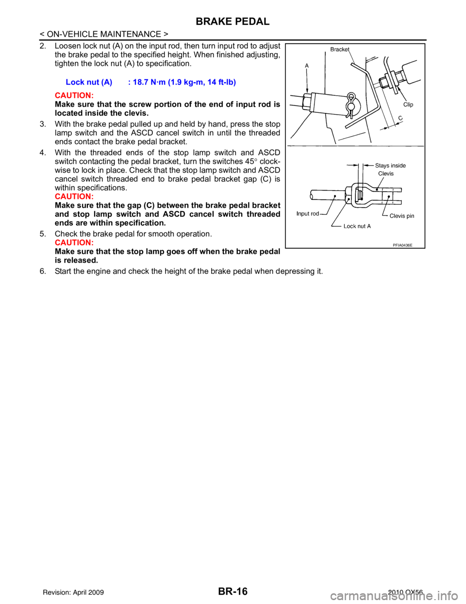
2. Loosen lock nut (A) on the input rod, then turn input rod to adjustthe brake pedal to the specified height. When finished adjusting,
tighten the lock nut (A) to specification.
CAUTION:
Make sure that the screw portion of the end of input rod is
located inside the clevis.
3. With the brake pedal pulled up and held by hand, press the stop lamp switch and the ASCD cancel switch in until the threaded
ends contact the brake pedal bracket.
4. With the threaded ends of the stop lamp switch and ASCD switch contacting the pedal bracket, turn the switches 45 ° clock-
wise to lock in place. Check that the stop lamp switch and ASCD
cancel switch threaded end to brake pedal bracket gap (C) is
within specifications.
CAUTION:
Make sure that the gap (C) between the brake pedal bracket
and stop lamp switch and ASCD cancel switch threaded
ends are within specification.
5. Check the brake pedal for smooth operation. CAUTION:
Make sure that the stop lamp goes off when the brake pedal
is released.
6. Start the engine and check the height of the brake pedal when depressing it. Lock nut (A) : 18.7 N·m (1.9 kg-m, 14 ft-lb)
PFIA0436E
Revision: April 20092010 QX56
Page 469 of 4210

BR-24
< ON-VEHICLE REPAIR >
BRAKE TUBE AND HOSE
1. Check brake lines (tubes and hoses), and connections for fluid leaks, damage, twist, deformation, contact
with other parts, and loose connections. Replace any parts as necessary. Refer to BR-13, "
Hydraulic Cir-
cuit".
2. While depressing brake pedal under a force of 785 N (80 kg-f, 177 lb-f) with engine running for approxi- mately 5 seconds, check each part for fluid leaks.
Revision: April 20092010 QX56
Page 471 of 4210

BR-26
< ON-VEHICLE REPAIR >
BRAKE BOOSTER
BRAKE BOOSTER
Removal and InstallationINFOID:0000000005147910
CAUTION:
• Be careful not to deform or bend brake piping while removing and installing brake booster.
• Replace clevis pin if it is damaged.
• Be careful not to damage brake booster stud bolt threads. If brake booster is tilted or inclined during
installation, dash panel may damage the threads.
• Attach the check valve in the correct direction.
REMOVAL
1. Remove engine room cover. Refer to EM-24, "Removal and Installation".
2. Remove engine air duct assembly. Refer to EM-25, "
Removal and Installation".
3. Remove cowl top extension. Refer to EXT-18, "
Removal and Installation".
4. Remove master cylinder assembly from brake booster. Refer to BR-25, "
Removal and Installation".
5. Remove vacuum hose from brake booster. Refer to BR-28, "
Removal and Installation".
6. Disconnect active boost and delta stroke s ensor harness connectors from brake booster.
7. Remove instrument lower panel LH. Refer to IP-14, "
Exploded View".
8. Remove brake pedal to clevis attachment snap pin and clevis pin from inside the vehicle.
9. Remove brake booster to brake pedal assembly nuts.
10. Reposition the A/C line out of the way.
11. Remove brake booster and spacer block from dash panel.
INSPECTION AFTER REMOVAL
Output Rod Length Inspection
1. Reservoir tank 2. Master cylinder assembly 3. Gasket
4. Brake pedal 5. Lock nut 6. Spacer block
7. Brake booster 8. Active booster 9. Delta stroke sensor
AWFIA0416GB
Revision: April 20092010 QX56
Page 472 of 4210

BRAKE BOOSTERBR-27
< ON-VEHICLE REPAIR >
C
DE
G H
I
J
K L
M A
B
BR
N
O P
1. Using a hand vacuum pump, apply a vacuum of – 66.7 kPa (– 500 mmHg, –19.69 inHg) to brake booster.
2. Check output rod length.
INSTALLATION
1. Loosen lock nut to adjust input r od length so that the length (B)
is set at the specified value.
2. After adjusting length (B), temporarily tighten lock nut and install brake booster and spacer block.
• Install the gaskets and spacer block between brake boosterand dash panel.
3. Connect brake pedal to clevis on the input rod.
4. Install brake booster to brake pedal assembly nuts and tighten to the specified torque.
5. Connect active boost and delta stroke s ensor harness connectors to brake booster.
6. Connect vacuum hose to brake booster.
7. Install master cylinder assembly to brake booster. Refer to BR-25, "
Removal and Installation".
8. Adjust the height and play of brake pedal. Refer to BR-15, "
Inspection and Adjustment".
9. Tighten lock nut of input rod to specification.
10. Install instrument lower panel LH. Refer to IP-14, "
Removal and Installation".
11. Secure A/C line into clips.
12. Install cowl top extension. Refer to EXT-18, "
Removal and Installation".
13. Install engine air duct assembly. Refer to EM-25, "
Removal and Installation".
14. Install engine room cover. Refer to EM-24, "
Removal and Installation".
15. Refill with new brake fluid and bleed air. Refer to BR-17, "
Bleeding Brake System".
Output rod length : Refer to
BR-46, "
Brake
Booster".
SBR208E
Input rod length (B) : Refer to BR-46, "Brake
Booster".
WFIA0382E
Revision: April 20092010 QX56
Page 473 of 4210

BR-28
< ON-VEHICLE REPAIR >
VACUUM LINES
VACUUM LINES
Removal and InstallationINFOID:0000000005147911
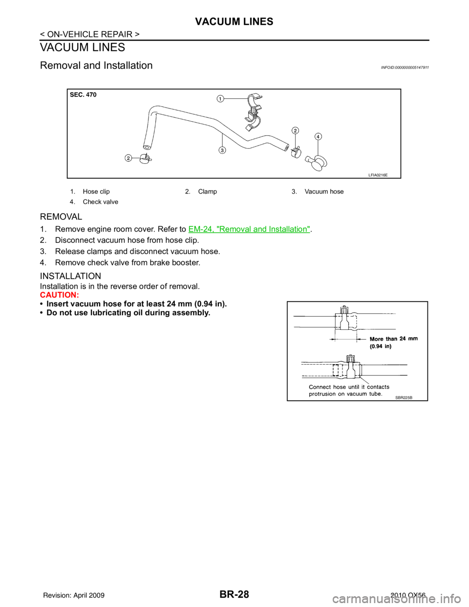
REMOVAL
1. Remove engine room cover. Refer to EM-24, "Removal and Installation".
2. Disconnect vacuum hose from hose clip.
3. Release clamps and disconnect vacuum hose.
4. Remove check valve from brake booster.
INSTALLATION
Installation is in the reverse order of removal.
CAUTION:
• Insert vacuum hose for at least 24 mm (0.94 in).
• Do not use lubricating oil during assembly.
1. Hose clip 2. Clamp3. Vacuum hose
4. Check valve
LFIA0216E
SBR225B
Revision: April 20092010 QX56