wheel torque INFINITI QX56 2010 Factory Owner's Manual
[x] Cancel search | Manufacturer: INFINITI, Model Year: 2010, Model line: QX56, Model: INFINITI QX56 2010Pages: 4210, PDF Size: 81.91 MB
Page 2736 of 4210

MA-32
< ON-VEHICLE MAINTENANCE >
CHASSIS AND BODY MAINTENANCE
DIFFERENTIAL GEAR OIL : Changi ng Rear Differential Gear Oil
INFOID:0000000005403157
DRAINING
1. Stop the engine.
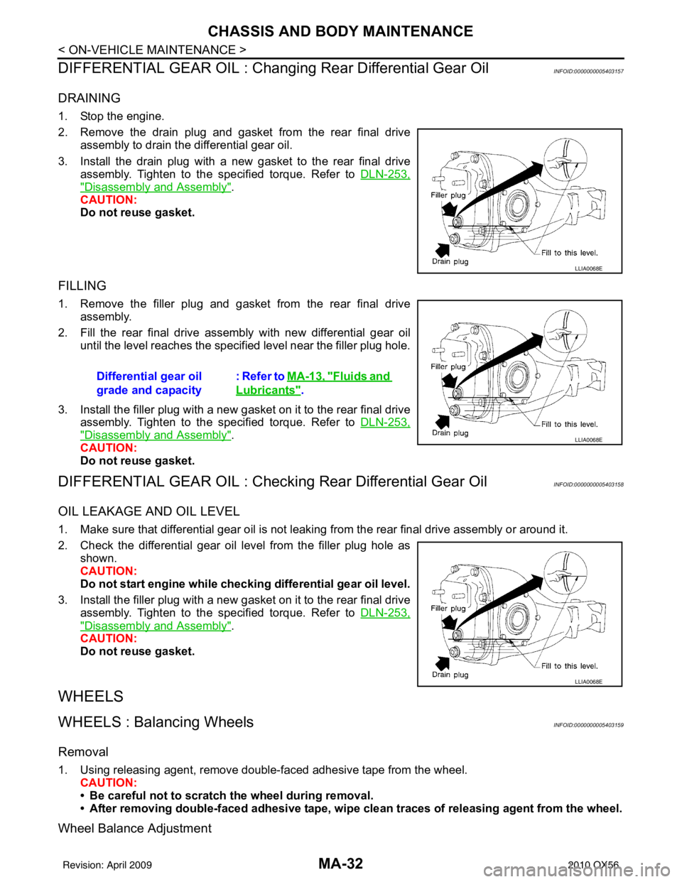
2. Remove the drain plug and gasket from the rear final drive
assembly to drain the differential gear oil.
3. Install the drain plug with a new gasket to the rear final drive assembly. Tighten to the specified torque. Refer to DLN-253,
"Disassembly and Assembly".
CAUTION:
Do not reuse gasket.
FILLING
1. Remove the filler plug and gasket from the rear final drive assembly.
2. Fill the rear final drive assembly with new differential gear oil until the level reaches the specified level near the filler plug hole.
3. Install the filler plug with a new gasket on it to the rear final drive assembly. Tighten to the specified torque. Refer to DLN-253,
"Disassembly and Assembly".
CAUTION:
Do not reuse gasket.
DIFFERENTIAL GEAR OIL : Checking Rear Differential Gear OilINFOID:0000000005403158
OIL LEAKAGE AND OIL LEVEL
1. Make sure that differential gear oil is not leaki ng from the rear final drive assembly or around it.
2. Check the differential gear oil level from the filler plug hole as shown.
CAUTION:
Do not start engine while checki ng differential gear oil level.
3. Install the filler plug with a new gasket on it to the rear final drive assembly. Tighten to the specified torque. Refer to DLN-253,
"Disassembly and Assembly".
CAUTION:
Do not reuse gasket.
WHEELS
WHEELS : Balancing WheelsINFOID:0000000005403159
Removal
1. Using releasing agent, remove double-faced adhesive tape from the wheel. CAUTION:
• Be careful not to scratch the wheel during removal.
• After removing double-faced adh esive tape, wipe clean traces of releasing agent from the wheel.
Wheel Balance Adjustment
LLIA0068E
Differential gear oil
grade and capacity: Refer to MA-13, "Fluids and
Lubricants".
LLIA0068E
LLIA0068E
Revision: April 20092010 QX56
Page 2738 of 4210

MA-34
< ON-VEHICLE MAINTENANCE >
CHASSIS AND BODY MAINTENANCE
Wheel balance (Maximum allowable imbalance):
WHEELS : RotationINFOID:0000000005403160
NOTE:
Follow the maintenance schedule for tire rotation service intervals. Refer to MA-9, "
Schedule 1" .
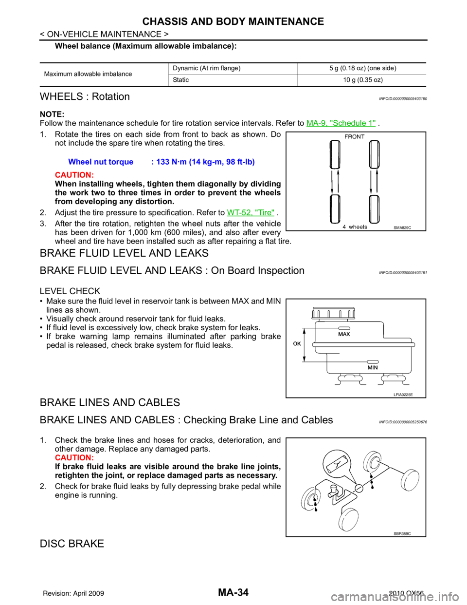
1. Rotate the tires on each side from front to back as shown. Do not include the spare tire when rotating the tires.
CAUTION:
When installing wheel s, tighten them diagonally by dividing
the work two to three times in order to prevent the wheels
from developing any distortion.
2. Adjust the tire pressure to specification. Refer to WT-52, "
Tire" .
3. After the tire rotation, retighten the wheel nuts after the vehicle has been driven for 1,000 km (600 miles), and also after every
wheel and tire have been installed such as after repairing a flat tire.
BRAKE FLUID LEVEL AND LEAKS
BRAKE FLUID LEVEL AND LEAK S : On Board InspectionINFOID:0000000005403161
LEVEL CHECK
• Make sure the fluid level in reservoir tank is between MAX and MIN
lines as shown.
• Visually check around reservoir tank for fluid leaks.
• If fluid level is excessively low, check brake system for leaks.
• If brake warning lamp remains illuminated after parking brake pedal is released, check brake system for fluid leaks.
BRAKE LINES AND CABLES
BRAKE LINES AND CABLES : Ch ecking Brake Line and CablesINFOID:0000000005259676
1. Check the brake lines and hoses for cracks, deterioration, and
other damage. Replace any damaged parts.
CAUTION:
If brake fluid leaks are visible around the brake line joints,
retighten the joint, or replace damaged parts as necessary.
2. Check for brake fluid leaks by fully depressing brake pedal while engine is running.
DISC BRAKE
Maximum allowable imbalance Dynamic (At rim flange) 5 g (0.18 oz) (one side)
Static
10 g (0.35 oz)
Wheel nut torque : 133 N·m (14 kg-m, 98 ft-lb)
SMA829C
LFIA0225E
SBR389C
Revision: April 20092010 QX56
Page 3216 of 4210

SERVICE DATA AND SPECIFICATIONS (SDS)RSU-29
< SERVICE DATA AND SPECIFICATIONS (SDS)
C
DF
G H
I
J
K L
M A
B
RSU
N
O P
SERVICE DATA AND SPECIFICATIONS (SDS)
SERVICE DATA AND SPECIFICATIONS (SDS)
Wheel AlignmentINFOID:0000000005148142
Ball JointINFOID:0000000005148143
Camber
Degree minute (decimal degree) Minimum
0° 0 ′ (0 °)
Nominal - 0° 30 ′ (-0.5 °)
Maximum - 1° 0 ′ (-1.0 °)
Cross camber 0° 45 ′ (0.75 °)
To e - i n Distance (A - B)
Minimum
0 mm (0 in)
Nominal 3.3 mm (0.130 in)
Maximum 6.6 mm (0.260 in)
Cross toe 2 mm (0.079 in)
Angle (left, right)
Degree minute (decimal degree) Minimum
0° 0 ′ (0 °)
Nominal 0° 7 ′ (0.11 °)
Maximum 0° 14 ′ (0.22 °)
Cross toe 0° 8 ′ (0.14 °)
SFA234AC
Swinging force (A)
(measurement point: cotter pin hole of ball stud) 11.4 - 145.5 N (1.16 - 14.8 kg, 2.56 - 32.7 lb)
Turning torque (B) 0.5 - 6.4 N·m (0.06 - 0.65 kg-m, 5 - 56 in-lb)
Vertical end play (C) 0 mm (0 in)
SFA858A
Revision: April 20092010 QX56
Page 3644 of 4210

ST-6
< PREPARATION >
PREPARATION
Commercial Service Tool
INFOID:0000000005147858
ST3127S000
(J-25765-A)
Preload gauge
1. GG9103000
(J-25765-A)
Torque wrench
2. HT62940000
(—)
Socket adapter
3. HT62900000
(—)
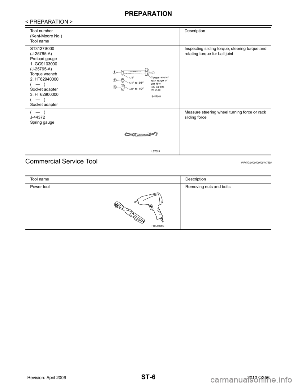
Socket adapter Inspecting sliding torque, steering torque and
rotating torque for ball joint
(—)
J-44372
Spring gauge Measure steering wheel turning force or rack
sliding force
Tool number
(Kent-Moore No.)
Tool name
Description
S-NT541
LST024
Tool name
Description
Power tool Removing nuts and bolts
PBIC0190E
Revision: April 20092010 QX56
Page 3650 of 4210

ST-12
< SYMPTOM DIAGNOSIS >
NOISE, VIBRATION AND HARSHNESS (NVH) TROUBLESHOOTING
SYMPTOM DIAGNOSIS
NOISE, VIBRATION AND HARSHNESS (NVH) TROUBLESHOOTING
NVH Troubleshooting ChartINFOID:0000000005147864
Use chart below to help you find the cause of the symp tom. If necessary, repair or replace these parts.
×: ApplicableReference page
ST-13, "
Checking Fluid Level
"
ST-13, "
Air Bleeding Hydraulic System
"
ST-36ST-36ST-36ST-13ST-35ST-37
EM-13, "
Checking Drive Belts
"
ST-35ST-35ST-37ST-35ST-20ST-37
DLN-184, "
NVH Troubleshooting Chart
"
DLN-208, "
NVH Troubleshooting Chart
"
FAX-5, "
NVH Troubleshooting Chart
"
FSU-5, "
NVH Troubleshooting Chart
"
WT-43, "
NVH Troubleshooting Chart
"
WT-43, "
NVH Troubleshooting Chart
"
FAX-5, "
NVH Troubleshooting Chart
"
BR-6, "
NVH Troubleshooting Chart
"
Possible cause and suspect-
ed parts
Fluid level
Air in hydraulic system
Outer socket ball joint swinging force
Outer socket ball joint rotating torque
Outer socket ball joint end play
Steering fluid leakage
Steering wheel play
Steering gear rack sliding force
Drive belt looseness
Improper steering wheel
Improper installation or looseness of tilt lock lever
Mounting rubber deterioration
Steering column deformation or damage
Improper installation or looseness of steering column
Steering linkage looseness
PROPELLER SHAFT
FRONT FINAL DRIVE
WHEEL HUB
SUSPENSION
TIRES
ROAD WHEEL
DRIVE SHAFT
BRAKES
Symptom
Noise
× × ××××× × × ××××××× ×
Shake ×××× ××××× ×
Vibration ××××× × ××× ×
Shimmy ××× × ×××× ×
Shudder × × ×××× ×
Revision: April 20092010 QX56
Page 3721 of 4210

TM-26
< FUNCTION DIAGNOSIS >
A/T CONTROL SYSTEM
When shifting from the lock-up released state to the lock-up applied state, the current output to the torque con-
verter clutch solenoid is controlled with the TCM. In th is way, when shifting to the lock-up applied state, the
torque converter clutch is temporarily set to the half-clutched state to reduce the shock.
Half-clutched State
• The current output from the TCM to the torque converte r clutch solenoid is varied to gradually increase the
torque converter clutch solenoid pressure.
In this way, the lock-up apply pressure gradually rises and while the torque converter clutch piston is put into
half-clutched status, the torque converter clutch piston operating pressure is increased and the coupling is
completed smoothly.
Slip Lock-up Control
• In the slip region, the torque converter clutch solenoid current is controlled with the TCM to put it into the
half-clutched state. This absorbs the engine tor que fluctuation and lock-up operates from low speed.
This raises the fuel efficiency for 4GR and 5GR at both low speed and when the accelerator has a low
degree of opening.
Engine Brake ControlINFOID:0000000005148516
• The forward one-way clutch transmits the drive force from the engine to the rear wheels. But the reverse drive from the rear wheels is not transmitted to the engine because the one-way clutch is idling.
Therefore, the low coast brake solenoid is operated to prevent the forward one-way clutch from idling and
the engine brake is operated in the same manner as conventionally.
• The operation of the low coast brake solenoid switches the low coast brake switching valve and controls the
coupling and releasing of the low coast brake.
The low coast brake reducing valve contro ls the low coast brake coupling force.
Control ValveINFOID:0000000005148517
FUNCTION OF CONTROL VALVE
SCIA1520E
Name Function
Torque converter regulator valve In order to prevent the pressure supplied to the torque converter from being excessive,
the line pressure is adjusted to the optimum pressure (torque converter operating pres-
sure).
Pressure regu lator valve
Pressure regulator plug
Pressure regu lator sleeve Adjusts the oil discharged from the oil pump to the optimum pressure (line pressure) for
the driving state.
Front brake control valve When the front brake is coupled, adjusts the line pressure to the optimum pressure (front
brake pressure) and supplies it to the front brake. (In 1GR, 2GR, 3GR, and 5GR, adjusts
the clutch pressure.)
Accumulator control valve Adjusts the pressure (accumulator control pressure) acting on the accumulator piston
and low coast reducing valve to the pressure appropriate to the driving state.
Revision: April 20092010 QX56
Page 3813 of 4210

TM-118
< ECU DIAGNOSIS >
TCM
Even when the electronic circuits are normal, under special conditions (for example, when slamming on the
brake with the wheels spinning drastically and stopping the tire rotation), the transmission can go into fail-safe
mode. If this happens, switch “OFF” the ignition switch for 10 seconds, then switch it “ON” again to return to
the normal shift pattern. Therefore, the customer's v ehicle has returned to normal, so handle according to the
“diagnostics flow” (Refer to TM-5, "
Work Flow").
FAIL-SAFE FUNCTION
If any malfunction occurs in a sensor or solenoid, th is function controls the A/T to mark driving possible.
Output Speed Sensor
• Signals are input from two systems - from output speed sensor installed on the transmission and from com-
bination meter so normal driving is possible even if there is a malfunction in one of the systems. And if output
speed sensor has unusual cases, 5GR is prohibited.
Accelerator Peda l Position Sensor
• If there is a malfunction in one of the systems, the accelerator opening angle is controlled by ECM according
to a pre-determined accelerator angle to make driving possible. And if there are malfunctions in tow sys-
tems, the engine speed is fixed by ECM to a pre-determined engine speed to make driving possible.
Throttle Position Sensor
• If there is a malfunction in one of the systems, the accelerator opening angle is controlled by ECM according
to a pre-determined accelerator angle to make driving possible. And if there are malfunctions in tow sys-
tems, the accelerator opening angle is controlled by the idle signal sent from the ECM which is based on
input indicating either idle condition or off-idle condition (pre-determined accelerator opening) in order to
make driving possible.
Transmission Range Switch
• In the unlikely event that a malfunction signal enters t he TCM, the position indicator is switched “OFF”, the
starter relay is switched “OFF” (starter starting is disabled), the back-up lamp relay switched “OFF” (back-up
lamp is OFF) and the position is fixed to the “D” position to make driving possible.
Starter Relay
• The starter relay is switched “OFF”. (Starter starting is disabled.)
Interlock
• If there is an interlock judgment malfunction, the trans mission is fixed in 2GR to make driving possible.
NOTE:
When the vehicle is driven fixed in 2GR, a input speed sensor malfunction is displayed, but this is
not a input speed sensor malfunction.
• When the interlock is detected at the 3GR or more, it is locked at the 2GR.
1st Engine Braking
• When there is an 1st engine brake judgment malfunction, the low coast brake solenoid is switched “OFF” to
avoid the engine brake operation.
Line Pressure Solenoid
• The solenoid is switched “OFF” and the line pressure is set to the maximum hydraulic pressure to make driv- ing possible.
Torque Converter Clutch Solenoid
• The solenoid is switched “OFF” to release the lock-up.
Low Coast Brake Solenoid
• When a (electrical or functional) malfunction occurs, in order to make driving possible, the engine brake isnot applied in 1GR and 2GR.
Input Clutch Solenoid
• If a (electrical or functional) malfunction occurs with the solenoid either “ON” or “OFF”, the transmission is
held in 4GR to make driving possible.
Direct Clutch Solenoid
• If a (electrical or functional) malfunction occurs with the solenoid either “ON” or “OFF”, the transmission is
held in 4GR to make driving possible.
Front Brake Solenoid
• If a (electrical or functional) malfunction occurs with the solenoid “ON”, in order to make driving possible, the
A/T is held in 5GR; if the solenoid is OFF, 4GR.
Revision: April 20092010 QX56
Page 4118 of 4210

WHEEL AND TIRE ASSEMBLYWT-49
< ON-VEHICLE REPAIR >
C
DF
G H
I
J
K L
M A
B
WT
N
O P
c. If calculated balance weight value exceeds 50 g (1.76 oz), install two balance weight sheets in line with each other as shown.
CAUTION:
Do not install one balance weig ht sheet on top of another.
3. Start wheel balancer again.
4. Install drive-in balance weight on inner side of road wheel in the wheel balancer indication position (angle).
CAUTION:
Do not install more than two balance weights.
5. Start wheel balancer. Make sure that inner and outer residual imbalance values are 5 g (0.18 oz) each or below.
• If either residual imbalance value exceeds 5 g (0.18 oz),repeat installation procedures.
Wheel balance (Maximum allowable imbalance):
RotationINFOID:0000000005148247
NOTE:
Follow the maintenance schedule for tire rotation service intervals. Refer to MA-6, "
General Maintenance" .
1. Rotate the tires on each side from front to back as shown. Do not include the spare tire when rotating the tires.
CAUTION:
When installing wheel s, tighten them diagonally by dividing
the work two to three times in order to prevent the wheels
from developing any distortion.
2. Adjust the tire pressure to specification. Refer to WT-52, "
Tire" .
3. After the tire rotation, retighten the wheel nuts after the vehicle has been driven for 1,000 km (600 miles), and also after every
wheel and tire have been installed such as after repairing a flat tire.
Maximum allowable imbalance Dynamic (At rim flange) 5 g (0.18 oz) (one side)
Static
10 g (0.35 oz)
SMA056D
Wheel nut torque : 133 N·m (14 kg-m, 98 ft-lb)
SMA829C
Revision: April 20092010 QX56