rear view mirror INFINITI QX60 2023 User Guide
[x] Cancel search | Manufacturer: INFINITI, Model Year: 2023, Model line: QX60, Model: INFINITI QX60 2023Pages: 636, PDF Size: 7.28 MB
Page 268 of 636

If one of the mirrors are manually operated or
bumped, the mirror body can become loose
at the pivot point. To correct electronic mirror
operation, cycle the mirrors by pushing the
switch
O1until completely closed, then push
the switch again until the mirrors are in the
open position
Automatic anti-glare outside mirror
(if so equipped)
The outside mirror will automatically dim dur-
ing nighttime conditions to reduce the glare
from the headlights of trailing vehicles. The
automatic anti-glare feature operates only
when the ignition switch is placed in the ON
position.
The automatic anti-glare feature will be on
when starting the vehicle. The indicator light
on the automatic anti-glare rearview mirror
will illuminate when the automatic anti-glare
feature is operating.
For additional information, see “Automatic
anti-glare rearview mirror” (P. 3-33).
Heated mirrors
The electric control type outside mirrors can
be heated to defrost, defog, or de-ice for
improved visibility. For additional informa-
tion, see “Rear window and outside mirror (if
so equipped) defroster switch” (P. 4-32).
Reverse tilt-down feature
The reverse tilt-down feature will turn the
selected left or right mirror surface down-
ward to provide better rear visibility close to
the vehicle. The mirror control switch must be
in either the L or R position.
The mirror automatically returns to the origi-
nal position when you shift out of R (Reverse).
The outside mirror surface will return to the
original position when one of the following
conditions has occurred:
• The shift lever is moved to any position other than R (Reverse).
• The outside mirror control switch is set to the neutral or center position.
• The ignition switch is placed in the OFF position. The reverse tilt position can be changed.
While in R (Reverse), adjust the glass position
to the desired location. The next time the
vehicle is shifted into R (Reverse), the glass
position will go to the newly set position.
Additionally, the changed reverse tilt position
can be saved to a memory seat position. After
the reverse tilt glass position has been
changed, vehicle is shifted back into park and
glass has returned to the original position,
push the Set switch and press the desired
memory switch (1 or 2) to assign the new
reverse tilt position memory.
NOTE:
If the outside mirror control switch is in the
center position, the mirror surface will NOT
turn downward when the shift lever is
moved to R (Reverse).
For additional information, see “Memory
seat” (P. 3-43).
3-42Pre-driving checks and adjustments
Page 273 of 636

1.button
2. CAMERA buttonWARNING
• Failure to follow the warnings and in-
structions for proper use of the Rear-
View Monitor system could result in se-
rious injury or death. •
RearView Monitor is a convenience fea-
ture and is not a substitute for proper
backing. Always turn and look out the
windows and check mirrors to be sure
that it is safe to move before operating
the vehicle. Always back up slowly.
LHA5526
REARVIEW MONITOR (if so
equipped)
Monitor, climate, audio, phone and voice recognition systems4-3
Page 279 of 636
•Objects viewed in the RearView Monitor
differ from actual distance because a
wide-angle lens is used.
• Objects in the RearView Monitor will ap-
pear visually opposite compared to when
viewed in the rearview and outside
mirrors.
• Use the displayed lines as a reference.
The lines are highly affected by the num-
ber of occupants, fuel level, vehicle posi-
tion, road conditions and road grade.
• Make sure that the liftgate is securely
closed when backing up.
• Do not put anything on the rearview
camera. The rearview camera is located
in back door finisher.
• When washing the vehicle with high
pressure water, be sure not to spray it
around the camera. Otherwise, water
may enter the camera unit causing water
condensation on the lens, a malfunction,
fire or an electric shock.
• Do not strike the camera. It is a precision
instrument. Otherwise, it may malfunc-
tion or cause damage resulting in a fire or
an electric shock. The following are operating limitations and
do not represent a system malfunction:
• When the temperature is extremely high or
low, the screen may not clearly display
objects.
• When strong light directly shines on the camera, objects may not be displayed
clearly.
• Vertical lines may be seen in objects on the screen. This is due to strong reflected light
from the bumper.
• The screen may flicker under fluorescent light.
• The colors of objects on the RearView Monitor may differ somewhat from the ac-
tual color of objects.
• Objects on the monitor may not be clear in a dark environment.
• There may be a delay when switching be- tween views.
• If dirt, rain or snow accumulates on the camera, the RearView Monitor may not
display objects clearly. Clean the camera.
• Do not use wax on the camera lens. Wipe off any wax with a clean cloth dampened
with a diluted mild cleaning agent, then
wipe with a dry cloth.
SYSTEM MAINTENANCE
CAUTION
• Do not use alcohol, benzine or thinner to
clean the camera. This will cause
discoloration.
• Do not damage the camera as the moni-
tor screen may be adversely affected.
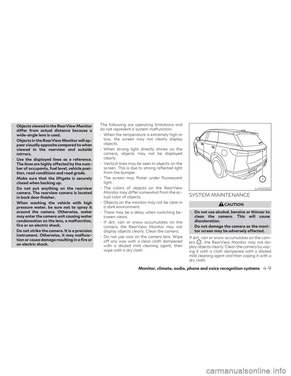
If dirt, rain or snow accumulates on the cam-
era
O1, the RearView Monitor may not dis-
play objects clearly. Clean the camera by wip-
ing it with a cloth dampened with a diluted
mild cleaning agent and then wiping it with a
dry cloth.
LHA5550
Monitor, climate, audio, phone and voice recognition systems4-9
Page 281 of 636

WARNING
• Failure to follow the warnings and in-
structions for the proper use of the
Around View® Monitor system could re-
sult in serious injury or death.
• The Around View® Monitor is a conve-
nience feature and is not a substitute for
proper vehicle operation because it has
areas where objects cannot be viewed.
The four corners of the vehicle in particu-
lar, are areas where objects do not al-
ways appear in the bird’s-eye, front, or
rear views. Always check your surround-
ings to be sure that it is safe to move
before operating the vehicle. Always op-
erate the vehicle slowly.
• The driver is always responsible for
safety during parking and other
maneuvers.
CAUTION
Do not scratch the camera lens when clean-
ing dirt or snow from the front of the
camera. The Around View® Monitor system is de-
signed as an aid to the driver in situations
such as slot parking or parallel parking.
The monitor displays various views of the
position of the vehicle in a split screen format.
Not all views are available at all times.
Available views:
• Front View
An approximately 150–degree view of the
front of the vehicle.
• Rear View An approximately 150–degree view of the
rear of the vehicle.
• Bird's-Eye View The surrounding views of the vehicle from
above.
• Front-Side View The view around and ahead of the front
passenger's side wheel.
• Front-Wide View An approximately 180–degree view of the
front the vehicle.
• Rear-Wide View An approximately 180–degree view of the
rear of the vehicle. To display the multiple views, the Around
View® Monitor system uses cameras located
in the front grille, on the vehicle’s outside
mirrors and one located in back door finisher
O1.
AROUND VIEW® MONITOR
SYSTEM OPERATION
With the ignition switch in the ON position,
move the shift lever to the R (Reverse) posi-
tion or press the CAMERA button to operate
the Around View® Monitor. When activating
the Around View® Monitor, the guide lines,
the icons and the messages may not be dis-
played immediately.
LHA5508
Monitor, climate, audio, phone and voice recognition systems4-11
Page 282 of 636
When the camera is first activated with the
bird’s-eye view in the display, a red icon will
flash on the screen. This indicates that the
sonar system is activated. For additional in-
formation on the front and rear sonar system,
see “Front and rear sonar system” (P. 5-172).
The screen displayed on the Around View®
Monitor will automatically return to the pre-
vious screen 3 minutes after the CAMERA or
button has been pressed with the shift
lever in a position other than the R (reverse)
position
Available views
WARNING
• The distance guide lines and the vehicle
width lines should be used as a reference
only when the vehicle is on a paved, level
surface. The apparent distance viewed
on the monitor may be different than the
actual distance between the vehicle and
displayed objects.
• Use the displayed lines and the bird’s-
eye view as a reference. The lines and the
bird’s-eye view are greatly affected by
the number of occupants, cargo, fuel
level, vehicle position, road condition
and road grade. •
If the tires are replaced with different
sized tires, the predicted course lines and
the bird's-eye view may be displayed
incorrectly.
• When driving the vehicle up a hill, objects
viewed in the monitor are further than
they appear. When driving the vehicle
down a hill, objects viewed in the monitor
are closer than they appear.
• Objects in the rear view will appear visu-
ally opposite compared to when viewed
in the monitor and outside mirrors.
• Use the mirrors or actually look to prop-
erly judge distances to other objects.
• On a snow-covered or slippery road,
there may be a difference between the
predicted course lines and the actual
course line.
• The vehicle width and predicted course
lines are wider than the actual width and
course.
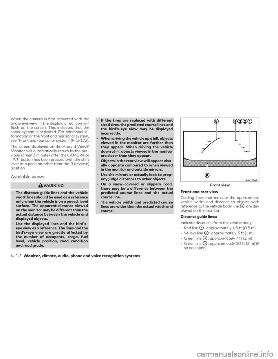
Front and rear view
Guiding lines that indicate the approximate
vehicle width and distance to objects with
reference to the vehicle body line
OAare dis-
played on the monitor.
Distance guide lines:
Indicate distances from the vehicle body:
• Red line
O1: approximately 1.5 ft (0.5 m)
• Yellow line
O2: approximately 3 ft (1 m)
• Green line
O3: approximately 7 ft (2 m)
• Green line
O4: approximately 10 ft (3 m) (if
so equipped)
SAA1840
Front view
4-12Monitor, climate, audio, phone and voice recognition systems
Page 285 of 636
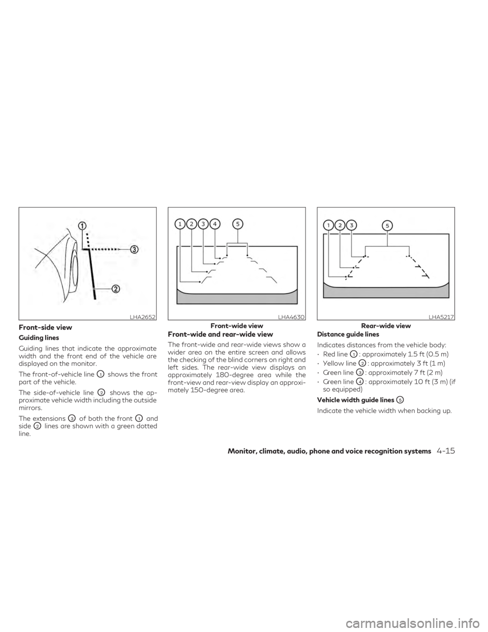
Front-side view
Guiding lines
Guiding lines that indicate the approximate
width and the front end of the vehicle are
displayed on the monitor.
The front-of-vehicle line
O1shows the front
part of the vehicle.
The side-of-vehicle line
O2shows the ap-
proximate vehicle width including the outside
mirrors.
The extensions
O3of both the frontO1and
side
O2lines are shown with a green dotted
line.
Front-wide and rear-wide view
The front-wide and rear-wide views show a
wider area on the entire screen and allows
the checking of the blind corners on right and
left sides. The rear-wide view displays an
approximately 180-degree area while the
front-view and rear-view display an approxi-
mately 150-degree area. Distance guide lines
Indicates distances from the vehicle body:
• Red line
O1: approximately 1.5 ft (0.5 m)
• Yellow line
O2: approximately 3 ft (1 m)
• Green line
O3: approximately 7 ft (2 m)
• Green line
O4: approximately 10 ft (3 m) (if
so equipped)
Vehicle width guide lines
O5
Indicate the vehicle width when backing up.
LHA2652LHA4630
Front-wide view
LHA5217
Rear-wide view
Monitor, climate, audio, phone and voice recognition systems4-15
Page 294 of 636
WARNING
• Failure to follow the warnings and in-
structions for proper use of the Moving
Object Detection system could result in
serious injury or death.
• The MOD system is not a substitute for
proper vehicle operation and is not de-
signed to prevent contact with objects
surrounding the vehicle. When maneu-
vering, always use the outside mirrors
and rearview mirror and turn and check
the surroundings to ensure it is safe to
maneuver.
• The system is deactivated at speeds
above 6 mph (10 km/h). It is reactivated
at lower speeds.
• The MOD system is not designed to de-
tect surrounding stationary objects.
The MOD system can inform the driver of
moving objects near the vehicle when back-
ing out of garages, maneuvering in parking
lots and in other such instances.
The MOD system detects moving objects by
using image processing technology on the
image shown in the display.MOD SYSTEM OPERATION
The MOD system will turn on automatically
under the following conditions:
• When the shift lever is in the R (Reverse) position.
• When the CAMERA button is pressed to activate the camera view on the display.
• When vehicle speed decreases below ap- proximately 6 mph (10 km/h) and the cam-
era screen is displayed.
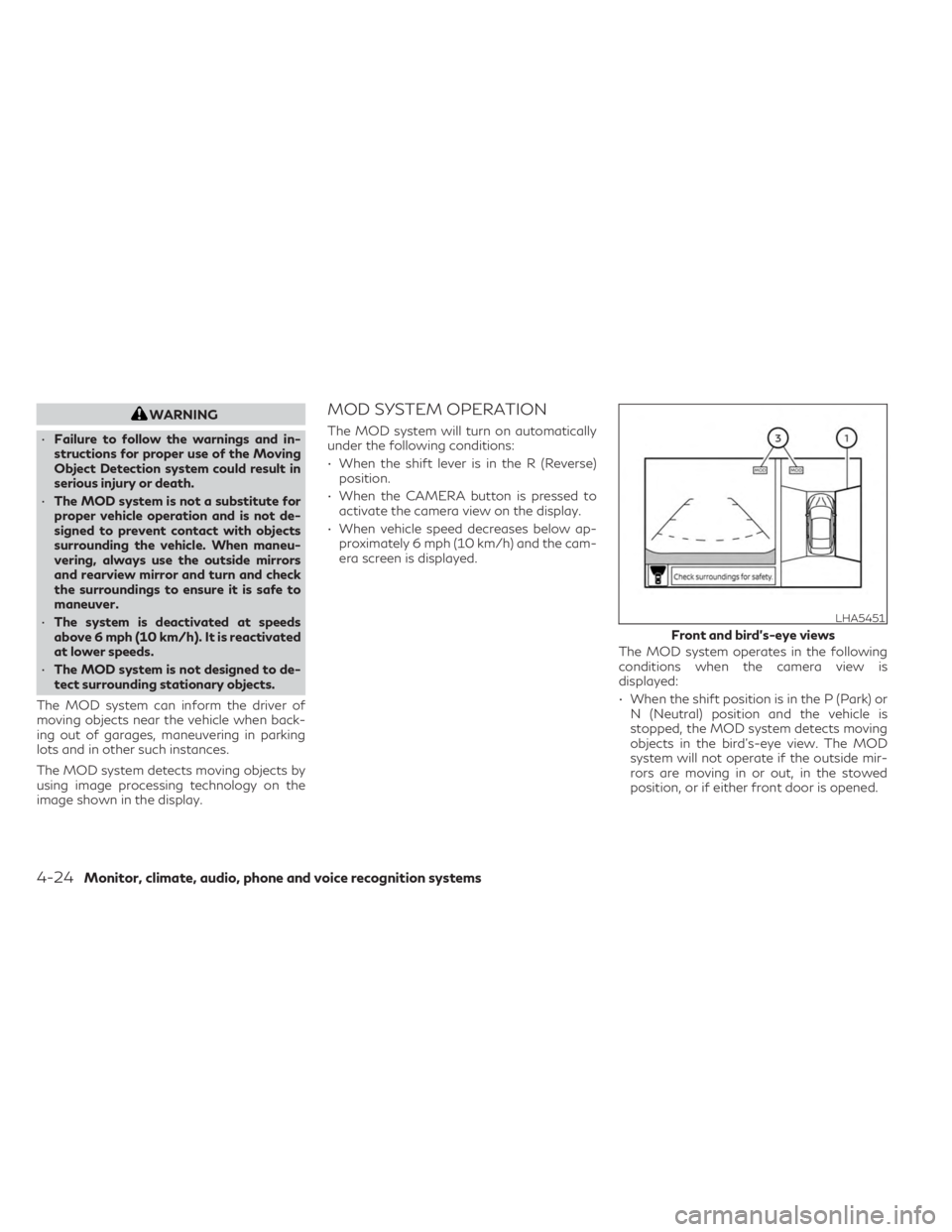
The MOD system operates in the following
conditions when the camera view is
displayed:
• When the shift position is in the P (Park) orN (Neutral) position and the vehicle is
stopped, the MOD system detects moving
objects in the bird’s-eye view. The MOD
system will not operate if the outside mir-
rors are moving in or out, in the stowed
position, or if either front door is opened.
LHA5451
Front and bird’s-eye views
4-24Monitor, climate, audio, phone and voice recognition systems
Page 296 of 636

TURNING MOD ON AND OFF
To turn the MOD system on or off:
1. Press the
orbutton on the
steering wheel and select “Settings” in the
vehicle information display.
2. Using the scroll dial, select “Driver Assis- tance” and press the OK button.
3. Select “Parking Aids”.
4. Toggle ON or OFF “Moving Object” using the OK button.
MOD SYSTEM LIMITATIONS
WARNING
Listed below are the system limitations for
MOD. Failure to operate the vehicle in ac-
cordance with these system limitations
could result in serious injury or death.
• Do not use the MOD system when tow-
ing a trailer. The system may not func-
tion properly.
• Excessive noise (for example, audio sys-
tem volume or open vehicle window) will
interfere with the chime sound, and it
may not be heard.
• The MOD system performance will be
limited according to environmental con-
ditions and surrounding objects such as:
– When there is low contrast between
background and the moving objects.
– When there is a blinking source of
light.
– When strong light such as another
vehicle’s headlight or sunlight is
present.
– When camera orientation is not in its
usual position, such as when a mirror
is folded.
– When there is dirt, water drops or
snow on the camera lens. –
When the position of the moving ob-
jects in the display is not changed.
• The MOD system might detect flowing
water droplets on the camera lens, white
smoke from the muffler, moving shad-
ows, etc.
• The MOD system may not function
properly depending on the speed, direc-
tion, distance or shape of the moving
objects.
• If your vehicle sustains damage to the
parts where the camera is installed, leav-
ing it misaligned or bent, the sensing
zone may be altered and the MOD sys-
tem may not detect objects properly.
• When the temperature is extremely high
or low, the screen may not display ob-
jects clearly. This is not a malfunction.
LHA5454
Rear-wide view
4-26Monitor, climate, audio, phone and voice recognition systems
Page 342 of 636
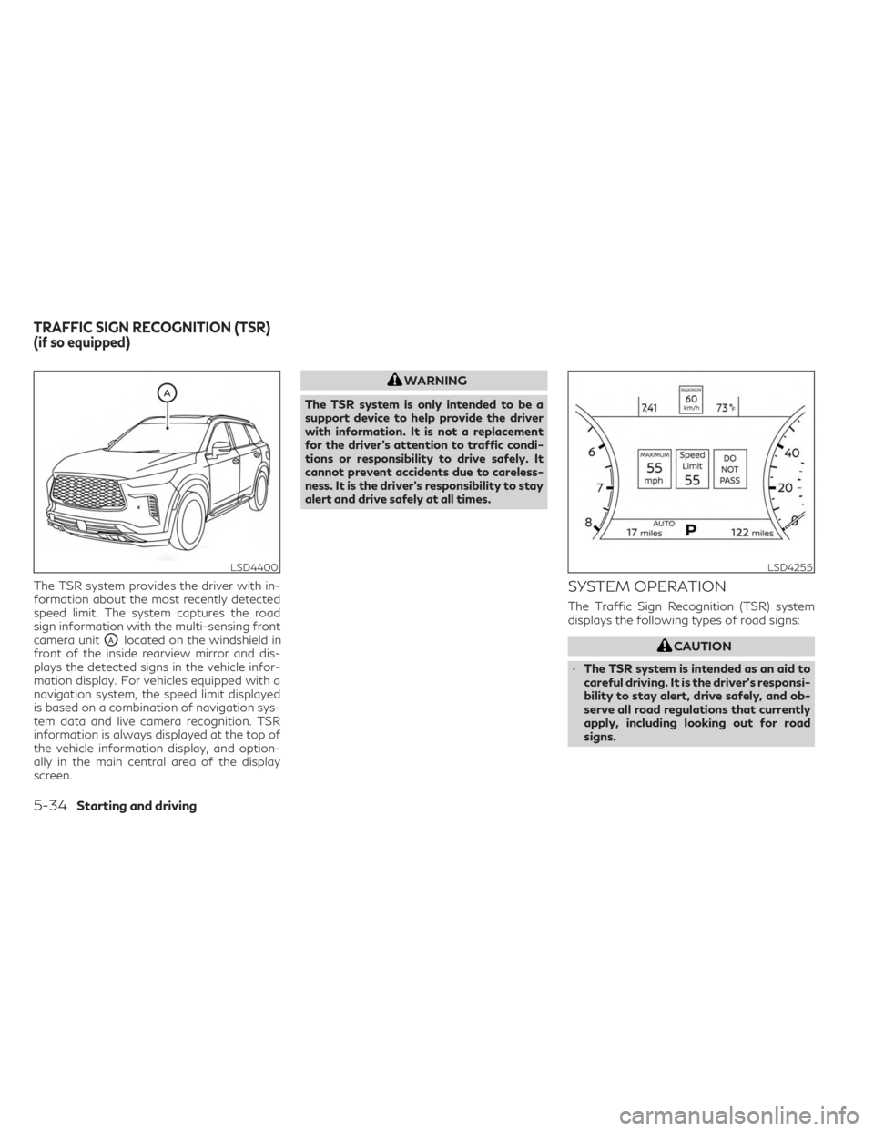
The TSR system provides the driver with in-
formation about the most recently detected
speed limit. The system captures the road
sign information with the multi-sensing front
camera unit
OAlocated on the windshield in
front of the inside rearview mirror and dis-
plays the detected signs in the vehicle infor-
mation display. For vehicles equipped with a
navigation system, the speed limit displayed
is based on a combination of navigation sys-
tem data and live camera recognition. TSR
information is always displayed at the top of
the vehicle information display, and option-
ally in the main central area of the display
screen.
WARNING
The TSR system is only intended to be a
support device to help provide the driver
with information. It is not a replacement
for the driver’s attention to traffic condi-
tions or responsibility to drive safely. It
cannot prevent accidents due to careless-
ness. It is the driver’s responsibility to stay
alert and drive safely at all times.
SYSTEM OPERATION
The Traffic Sign Recognition (TSR) system
displays the following types of road signs:
CAUTION
• The TSR system is intended as an aid to
careful driving. It is the driver’s responsi-
bility to stay alert, drive safely, and ob-
serve all road regulations that currently
apply, including looking out for road
signs.
LSD4400LSD4255
TRAFFIC SIGN RECOGNITION (TSR)
(if so equipped)
5-34Starting and driving
Page 344 of 636
![INFINITI QX60 2023 User Guide SYSTEM TEMPORARILY
UNAVAILABLE
If the vehicle is parked in direct sunlight under
high temperature conditions (over approxi-
mately 104°F [40°C]) and then started, the
TSR system may be deactivated a INFINITI QX60 2023 User Guide SYSTEM TEMPORARILY
UNAVAILABLE
If the vehicle is parked in direct sunlight under
high temperature conditions (over approxi-
mately 104°F [40°C]) and then started, the
TSR system may be deactivated a](/img/42/58899/w960_58899-343.png)
SYSTEM TEMPORARILY
UNAVAILABLE
If the vehicle is parked in direct sunlight under
high temperature conditions (over approxi-
mately 104°F [40°C]) and then started, the
TSR system may be deactivated automati-
cally. The “Unavailable: High Cabin Tempera-
ture” warning message will appear in the ve-
hicle information display.
Action to take:
When the interior temperature is reduced, the
TSR system will resume operating automati-
cally.
SYSTEM MALFUNCTION
If the TSR system malfunctions, it will be
turned off automatically and the system
“Malfunction” warning message will appear
in the vehicle information display.
Action to take:
If the TSR “Malfunction” message appears,
pull off the road at a safe location and stop
the vehicle. Turn the engine off and restart
the engine. If the TSR “Malfunction” message
continues to appear, have the system
checked. It is recommended that you visit an
INFINITI retailer for this service.
SYSTEM MAINTENANCE
The TSR system uses the same multi-sensing
front camera unit that is used by the Lane
Departure Warning (LDW) system, located in
front of the interior rearview mirror. For ad-
ditional information, see ”System mainte-
nance” (P. 5-42).
WARNING
Failure to follow the warnings and instruc-
tions for proper use of the LDW system
could result in serious injury or death.
• This system is only a warning device to
inform the driver of a potential unin-
tended lane departure. It will not steer
the vehicle or prevent loss of control. It is
the driver’s responsibility to stay alert,
drive safely, keep the vehicle in the trav-
eling lane, and be in control of the vehicle
at all times.
LSD4400
LANE DEPARTURE WARNING (LDW)
5-36Starting and driving