fuel INFINITI QX60 2023 Owner's Manual
[x] Cancel search | Manufacturer: INFINITI, Model Year: 2023, Model line: QX60, Model: INFINITI QX60 2023Pages: 636, PDF Size: 7.28 MB
Page 161 of 636
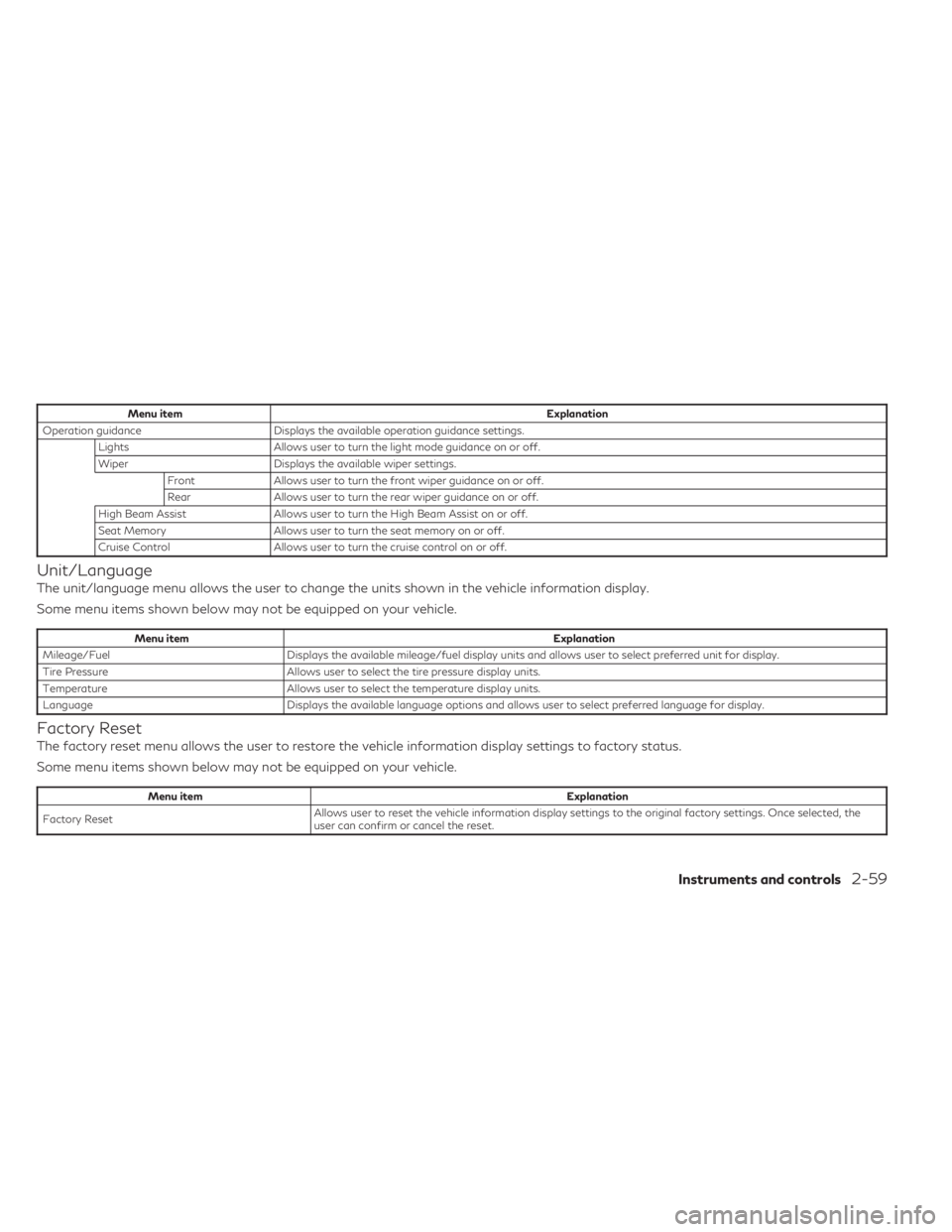
Menu itemExplanation
Operation guidance Displays the available operation guidance settings.
Lights Allows user to turn the light mode guidance on or off.
Wiper Displays the available wiper settings.
Front Allows user to turn the front wiper guidance on or off.
Rear Allows user to turn the rear wiper guidance on or off.
High Beam Assist Allows user to turn the High Beam Assist on or off.
Seat Memory Allows user to turn the seat memory on or off.
Cruise Control Allows user to turn the cruise control on or off.
Unit/Language
The unit/language menu allows the user to change the units shown in the vehicle information display.
Some menu items shown below may not be equipped on your vehicle.
Menu item Explanation
Mileage/Fuel Displays the available mileage/fuel display units and allows user to select preferred unit for display.
Tire Pressure Allows user to select the tire pressure display units.
Temperature Allows user to select the temperature display units.
Language Displays the available language options and allows user to select preferred language for display.
Factory Reset
The factory reset menu allows the user to restore the vehicle information display settings to factory status.
Some menu items shown below may not be equipped on your vehicle.
Menu item Explanation
Factory Reset Allows user to reset the vehicle information display settings to the original factory settings. Once selected, the
user can confirm or cancel the reset.
Instruments and controls2-59
Page 164 of 636

Headlight System Error: See Owner’s
Manual
This warning appears when there is an error
with the system. For additional information,
see “Headlight and turn signal switch” (P. 2-77).
High Beam Assist indicator
(green)
This indicator appears when the headlights
come on while the headlight switch is in the
AUTO position with the high beams selected
and the engine running. This indicates that
the high beam assist is operational.
For additional information, see “Headlight
and turn signal switch” (P. 2-77).
High beam indicator (blue)
This blue indicator appears when the head-
light high beams are on and goes out when
the low beams are selected.
The high beam indicator also appears when
the passing signal is activated.
INFINITI Drive Mode Selector indicator
When a driving mode is selected using the
INFINITI Drive Mode Selector, the selected
mode indicator is displayed.
• PERSONAL
• SPORT• STANDARD (2WD models)
• AUTO (AWD models)
• ECO
• SNOW
For additional information, see “INFINITI
Drive Mode Selector” (P. 5-29).
Low beam indicator
This indicator appears when the switch is
turned to theposition. The headlights
will come on; and the front side, tail, number
plate, and instrument lights remain on.
Low Fuel
This warning appears when the fuel level in
the fuel tank is getting low. Refuel as soon as
it is convenient, preferably before the fuel
gauge reaches 0 (Empty). There will be a
small reserve of fuel in the tank when the fuel
gauge needle reaches 0 (Empty).
Low Oil Pressure: See
Owner’s Manual
This warning appears in the message area of
the vehicle information display if low oil pres-
sure is detected. This gauge is not designed
to indicate low oil level. The low oil pressure
warning is not designed to indicate a low oil level.
Use the dipstick to check the oil level.
For additional information, see “Engine oil”
(P. 8-6).
Low Outside Temperature
This warning appears if the outside tempera-
ture is below 37°F (3°C). The temperature
can be changed to display in Celsius or Fahr-
enheit. For additional information, see “Driver
Assistance” (P. 2-51).
Low Washer Fluid
This warning appears when the windshield-
washer fluid is at a low level. Add windshield-
washer fluid as necessary. For additional infor-
mation, see “Windshield-washer fluid” (P. 8-11).
Low tire pressure indicator
Your vehicle is equipped with a Tire Pressure
Monitoring System (TPMS) that monitors the
tire pressure of all tires except the spare.
The low tire pressure indicator warns of low
tire pressure or indicates that the TPMS is
not functioning properly.
After the ignition switch is placed in the ON
position, this indicator appears for about 1
second and turns off.
2-62Instruments and controls
Page 166 of 636
•When using a wheel without the TPMS
such as the spare tire, the TPMS will not
function and the low tire pressure indica-
tor will flash for approximately 1 minute.
The indicator will remain on after 1 min-
ute. Have your tires replaced and/or
TPMS system reset as soon as possible.
It is recommended that you visit an
INFINITI retailer for these services.
• Replacing tires with those not originally
specified by INFINITI could affect the
proper operation of the TPMS.
CAUTION
• The TPMS is not a substitute for the
regular tire pressure check. Be sure to
check the tire pressure regularly.
• If the vehicle is being driven at speeds of
less than 16 mph (25 km/h), the TPMS
may not operate correctly.
• Be sure to install the specified size of
tires to the four wheels correctly.
Malfunction Indicator (MIL)
If this indicator appears steady or blinks while
the engine is running, it may indicate a poten-
tial emission control malfunction. The MIL may also come on steady if the
vehicle runs out of fuel. Check to make sure
that the vehicle has at least 3 gallons (11.4
liters) of fuel in the fuel tank.
After a few driving trips, the
indicator
should turn off if no other potential emission
control system malfunction exists.
If this indicator appears steady for 20 seconds
and then blinks for 10 seconds when the en-
gine is not running, it indicates that the vehicle
is not ready for an emission control system
inspection/maintenance test. For additional
information, see “Readiness for Inspection/
Maintenance (I/M) test” (P. 10-34).
Operation
The MIL will come on in one of two ways:
• MIL on steady — An emission control sys- tem malfunction has been detected. Have
the vehicle inspected. It is recommended
that you visit an INFINITI retailer for this
service. You do not need to have your ve-
hicle towed to the retailer.
• MIL blinking — An engine misfire has been detected which may damage the emission
control system. To reduce or avoid emis-
sion control system damage:– do not drive at speeds above 45 mph (72 km/h). – avoid hard acceleration or deceleration.
– avoid steep uphill grades.
– if possible, reduce the amount of cargo
being hauled or towed.
The MIL may stop blinking and come on
steady. Have the vehicle inspected. It is rec-
ommended that you visit an INFINITI retailer
for this service. You do not need to have your
vehicle towed to the retailer.
CAUTION
Continued vehicle operation without hav-
ing the emission control system checked
and repaired as necessary could lead to
poor driveability, reduced fuel economy,
and possible damage to the emission con-
trol system.
Master warning indicator
When the ignition is in the ON position, the
master warning indicator appears with vari-
ous other warning messages.
For additional information, see “Vehicle in-
formation display–7 inch (18 cm) Type A”
(P. 2-22) or “Vehicle information display—
12.3 inch (31 cm) Type B” (P. 2-44).
2-64Instruments and controls
Page 226 of 636

3 Pre-driving checks and adjustments
Keys.............................................3-2
INFINITI Intelligent Key .......................3-2
INFINITI Vehicle Immobilizer System
keys ..........................................3-3
Doors ...........................................3-4
Locking with key ..............................3-4
Locking with inside lock knob ..................3-5
Locking with power door lock switch ..........3-5
Automatic door locks .........................3-6
Child safety rear door lock .....................3-6
INFINITI Intelligent Key System ...................3-6
Operating range ..............................3-8
Door locks/unlocks precaution ................3-9
INFINITI Intelligent Key operation .............3-9
How to use the remote keyless entry
function .................................... 3-14
Warning signals ............................. 3-16
Troubleshooting guide ......................3-16
Remote Engine Start (if so equipped) ...........3-18
Remote Engine Start operating range ........3-18
Remote starting the vehicle ..................3-19
Extending engine run time ...................3-19
Canceling a Remote Engine Start ............3-19
Conditions the Remote Engine Start will
not work ................................... 3-20Hood
.......................................... 3-21
Liftgate ....................................... 3-21
Operating the power liftgate ................3-22
Motion-Activated Liftgate
(if so equipped) ............................. 3-24
Liftgate release ............................. 3-25
Liftgate position setting .....................3-26
Fuel-filler door ................................. 3-27
Opening the fuel-filler door ..................3-27
How to refuel ............................... 3-28
When refueling from a portable fuel
container ................................... 3-30
Steering wheel ................................. 3-30
Manual operation (if so equipped) ...........3-31
Automatic operation (if so equipped) .........3-31
Sun visors ..................................... 3-32
Vanity mirrors .............................. 3-33
Card holder ................................. 3-33
Mirrors ........................................ 3-33
Automatic
anti-glare rearview mirror
(if so equipped) ............................. 3-33
Smart rear view mirror (if so equipped) .......3-34
Outside mirrors ............................. 3-41
Page 253 of 636

3. Press and hold the power liftgate closeswitch
OBlocated on the liftgate for more
than 3 seconds or until two beeps are
heard.
The liftgate will open to the selected position
setting. To change the position of the liftgate,
repeat steps 1-3 for setting the position of
the liftgate.
OPENING THE FUEL-FILLER
DOOR
To open the fuel-filler door, push the right
side of the fuel-filler door to release.
WARNING
• Gasoline is extremely flammable and
highly explosive under certain condi-
tions. You could be burned or seriously
injured if it is misused or mishandled. Al-
ways stop the engine and do not smoke
or allow open flames or sparks near the
vehicle when refueling. •
Do not attempt to top off the fuel tank
after the fuel pump nozzle shuts off au-
tomatically. Continued refueling may
cause fuel overflow, resulting in fuel
spray and possibly a fire.
• Never pour fuel into the throttle body to
attempt to start your vehicle.
• Do not fill a portable fuel container in the
vehicle or trailer. Static electricity can
cause an explosion of flammable liquid,
vapor or gas in any vehicle or trailer. To
reduce the risk of serious injury or death
when filling portable fuel containers:
– Always place the container on the
ground when filling.
– Do not use electronic devices when
filling.
– Keep the pump nozzle in contact with
the container while you are filling it.
– Use only approved portable fuel con-
tainers for flammable liquid.
LPD2725
FUEL-FILLER DOOR
Pre-driving checks and adjustments3-27
Page 254 of 636
CAUTION
• Do not use a fuel containing more than
15% ethanol in your vehicle. For addi-
tional information, see “Fuel recommen-
dation” (P. 10-4).
•
For additional information, see “Malfunc-
tion Indicator Light (MIL)” (P. 2-19).
• If fuel is spilled on the vehicle body, flush
it away with water to avoid paint
damage.
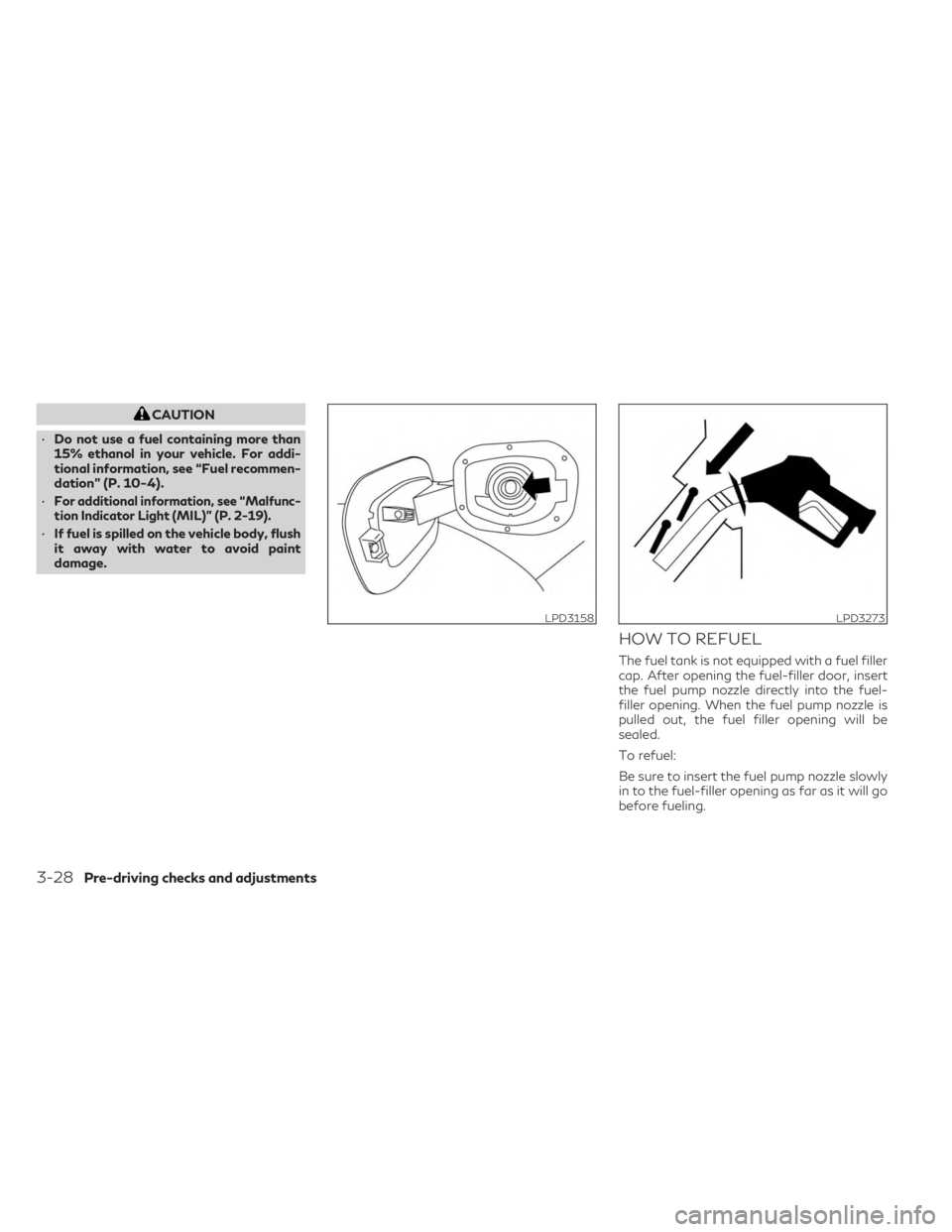
HOW TO REFUEL
The fuel tank is not equipped with a fuel filler
cap. After opening the fuel-filler door, insert
the fuel pump nozzle directly into the fuel-
filler opening. When the fuel pump nozzle is
pulled out, the fuel filler opening will be
sealed.
To refuel:
Be sure to insert the fuel pump nozzle slowly
in to the fuel-filler opening as far as it will go
before fueling.
LPD3158LPD3273
3-28Pre-driving checks and adjustments
Page 255 of 636

Never move the nozzle during the refueling.
Pull out the nozzle approximately 5 seconds
after the fuel pump nozzle shuts off auto-
matically (initial shut-off).
Close the fuel-filler door after refueling.
If you need to refuel from a portable fuel
container, use the funnel supplied with your
vehicle. (see “When refueling from a portable
fuel container” (P. 3-30).
CAUTION
• Do not attempt to open the flaps on the
fuel-filler opening using any tool other
than the fuel pump nozzle.
• This fuel-filler opening is only conform-
able to normal fuel pump nozzles at gas
stations. Using a nozzle with a small di-
ameter may damage the opening and the
fuel system.
• If fuel is spilled on the vehicle body, flush
it away with water to avoid paint
damage.
WARNING
• Gasoline is extremely flammable and
highly explosive under certain condi-
tions. You could be burned or seriously
injured if it is misused or mishandled. Al-
ways stop the engine and do not smoke
or allow open flames or sparks near the
vehicle when refueling.
• Do not attempt to top off the fuel tank
after the fuel pump nozzle shuts off au-
tomatically. Continued refueling may
cause fuel overflow, resulting in fuel
spray and possibly a fire.
• Never pour fuel into the throttle body to
attempt to start your vehicle.
• Do not fill a portable fuel container in the
vehicle or trailer. Static electricity can
cause an explosion of flammable liquid,
vapor or gas in any vehicle or trailer. To
reduce the risk of serious injury or death
when filling portable fuel containers:
– Always place the container on the
ground when filling.
– Do not use electronic devices when
filling. –
Keep the pump nozzle in contact with
the container while you are filling it.
– Use only approved portable fuel con-
tainers for flammable liquid.
Pre-driving checks and adjustments3-29
Page 256 of 636
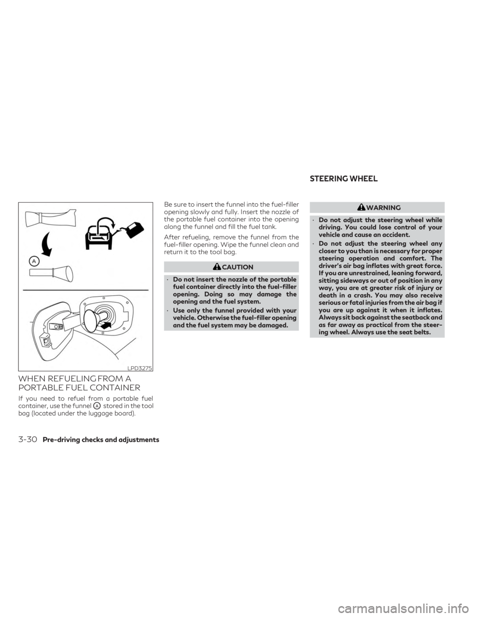
WHEN REFUELING FROM A
PORTABLE FUEL CONTAINER
If you need to refuel from a portable fuel
container, use the funnel
OAstored in the tool
bag (located under the luggage board). Be sure to insert the funnel into the fuel-filler
opening slowly and fully. Insert the nozzle of
the portable fuel container into the opening
along the funnel and fill the fuel tank.
After refueling, remove the funnel from the
fuel-filler opening. Wipe the funnel clean and
return it to the tool bag.
CAUTION
• Do not insert the nozzle of the portable
fuel container directly into the fuel-filler
opening. Doing so may damage the
opening and the fuel system.
• Use only the funnel provided with your
vehicle. Otherwise the fuel-filler opening
and the fuel system may be damaged.
WARNING
• Do not adjust the steering wheel while
driving. You could lose control of your
vehicle and cause an accident.
• Do not adjust the steering wheel any
closer to you than is necessary for proper
steering operation and comfort. The
driver's air bag inflates with great force.
If you are unrestrained, leaning forward,
sitting sideways or out of position in any
way, you are at greater risk of injury or
death in a crash. You may also receive
serious or fatal injuries from the air bag if
you are up against it when it inflates.
Always sit back against the seatback and
as far away as practical from the steer-
ing wheel. Always use the seat belts.
LPD3275
STEERING WHEEL
3-30Pre-driving checks and adjustments
Page 279 of 636
•Objects viewed in the RearView Monitor
differ from actual distance because a
wide-angle lens is used.
• Objects in the RearView Monitor will ap-
pear visually opposite compared to when
viewed in the rearview and outside
mirrors.
• Use the displayed lines as a reference.
The lines are highly affected by the num-
ber of occupants, fuel level, vehicle posi-
tion, road conditions and road grade.
• Make sure that the liftgate is securely
closed when backing up.
• Do not put anything on the rearview
camera. The rearview camera is located
in back door finisher.
• When washing the vehicle with high
pressure water, be sure not to spray it
around the camera. Otherwise, water
may enter the camera unit causing water
condensation on the lens, a malfunction,
fire or an electric shock.
• Do not strike the camera. It is a precision
instrument. Otherwise, it may malfunc-
tion or cause damage resulting in a fire or
an electric shock. The following are operating limitations and
do not represent a system malfunction:
• When the temperature is extremely high or
low, the screen may not clearly display
objects.
• When strong light directly shines on the camera, objects may not be displayed
clearly.
• Vertical lines may be seen in objects on the screen. This is due to strong reflected light
from the bumper.
• The screen may flicker under fluorescent light.
• The colors of objects on the RearView Monitor may differ somewhat from the ac-
tual color of objects.
• Objects on the monitor may not be clear in a dark environment.
• There may be a delay when switching be- tween views.
• If dirt, rain or snow accumulates on the camera, the RearView Monitor may not
display objects clearly. Clean the camera.
• Do not use wax on the camera lens. Wipe off any wax with a clean cloth dampened
with a diluted mild cleaning agent, then
wipe with a dry cloth.
SYSTEM MAINTENANCE
CAUTION
• Do not use alcohol, benzine or thinner to
clean the camera. This will cause
discoloration.
• Do not damage the camera as the moni-
tor screen may be adversely affected.
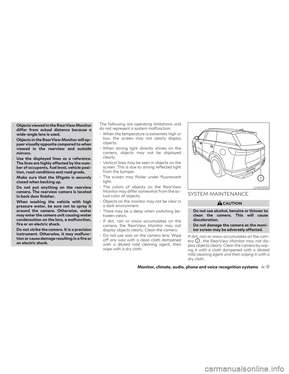
If dirt, rain or snow accumulates on the cam-
era
O1, the RearView Monitor may not dis-
play objects clearly. Clean the camera by wip-
ing it with a cloth dampened with a diluted
mild cleaning agent and then wiping it with a
dry cloth.
LHA5550
Monitor, climate, audio, phone and voice recognition systems4-9
Page 282 of 636
When the camera is first activated with the
bird’s-eye view in the display, a red icon will
flash on the screen. This indicates that the
sonar system is activated. For additional in-
formation on the front and rear sonar system,
see “Front and rear sonar system” (P. 5-172).
The screen displayed on the Around View®
Monitor will automatically return to the pre-
vious screen 3 minutes after the CAMERA or
button has been pressed with the shift
lever in a position other than the R (reverse)
position
Available views
WARNING
• The distance guide lines and the vehicle
width lines should be used as a reference
only when the vehicle is on a paved, level
surface. The apparent distance viewed
on the monitor may be different than the
actual distance between the vehicle and
displayed objects.
• Use the displayed lines and the bird’s-
eye view as a reference. The lines and the
bird’s-eye view are greatly affected by
the number of occupants, cargo, fuel
level, vehicle position, road condition
and road grade. •
If the tires are replaced with different
sized tires, the predicted course lines and
the bird's-eye view may be displayed
incorrectly.
• When driving the vehicle up a hill, objects
viewed in the monitor are further than
they appear. When driving the vehicle
down a hill, objects viewed in the monitor
are closer than they appear.
• Objects in the rear view will appear visu-
ally opposite compared to when viewed
in the monitor and outside mirrors.
• Use the mirrors or actually look to prop-
erly judge distances to other objects.
• On a snow-covered or slippery road,
there may be a difference between the
predicted course lines and the actual
course line.
• The vehicle width and predicted course
lines are wider than the actual width and
course.
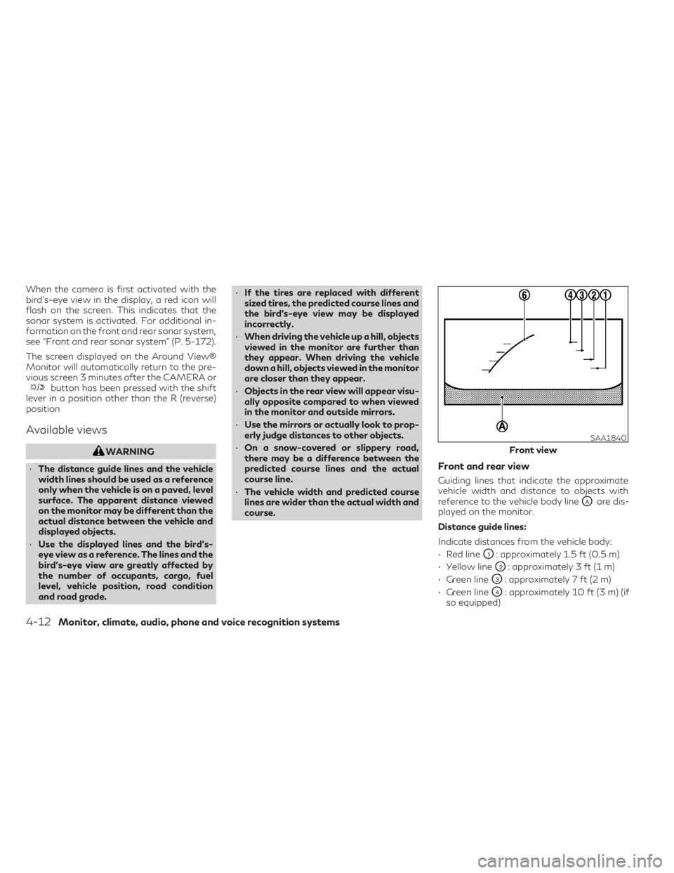
Front and rear view
Guiding lines that indicate the approximate
vehicle width and distance to objects with
reference to the vehicle body line
OAare dis-
played on the monitor.
Distance guide lines:
Indicate distances from the vehicle body:
• Red line
O1: approximately 1.5 ft (0.5 m)
• Yellow line
O2: approximately 3 ft (1 m)
• Green line
O3: approximately 7 ft (2 m)
• Green line
O4: approximately 10 ft (3 m) (if
so equipped)
SAA1840
Front view
4-12Monitor, climate, audio, phone and voice recognition systems