INFINITI QX60 HYBRID 2014 First Responder´s
Manufacturer: INFINITI, Model Year: 2014, Model line: QX60 HYBRID, Model: INFINITI QX60 HYBRID 2014Pages: 44, PDF Size: 4.68 MB
Page 31 of 44

12. Disconnect negative (-) battery cable and cover it withinsulated tape.
13. Perform the first response action.
3-3.2 Water Submersion
Damage level of submerged vehicle may not be apparent. Handling a submerged
vehicle without appropriate Personal Protective Equipment (PPE) will result in serious
injury or death from electrical shock.
•The ignition switch of the submerged vehicle must be turned OFF first, if possible.
Then the vehicle must be completely out of the water and drained to avoid electrical shock.
•
Always wear appropriate Personal Protective Equipment (PPE) and remove/drain
water before removing the service plug when working on a vehicle after a fire or
submersion to avoid electrical shock.
•
If the vehicle is in the water, to avoid electrical shock NEVER touch the high voltage
components, harnesses or service plug. PPE must always be worn when touching or
working on high voltage components.
AAYIA0274ZZ
FRG–31
Page 32 of 44

3-3.3 Vehicle Fire
• Always utilize full Personal Protective Equipment (PPE) and self-contained breathingapparatus during fire fighting operations. Smoke from a QX60 HYBRID vehicle fire is
similar to smoke from a conventional vehicle fire.
• In the case of extinguishing a fire with water, large amounts of water from a fire hydrant (if possible) must be used. DO NOT extinguish fire with a small amount of water.
In the event of a small fire, a Type ABC fire extinguisher may be used for an electrical fire
caused by wiring harnesses, electrical components, etc. or oil fire.
Fire attack should follow standard fire fighting practices.
If you must walk away from the vehicle, notify an appropriate responder or a rescue person of the fact that
the vehicle is a hybrid vehicle and contains a high voltage system and warn all others.
During overhaul operations (late stage fire suppression process to examine for remaining sources of heat) ,
make sure the battery is fully cooled to avoid fire re-ignition. The battery could reignite if it is placed near fire.
To avoid possible electrical shock and serious personal injury, do not breach the Li-ion battery case.
3-3.4 Cutting the Vehicle Body
•Do not cut into high voltage related areas to avoid severe personal injury or death.
•
Do not cut into the Li-ion battery to avoid severe personal injury or death.
•
When removing parts, NEVER touch the high voltage parts or the insides of the
exposed orange-colored high voltage cables to avoid severe personal injury or death.
Personal Protective Equipment (PPE) must always be worn when touching or
working on high voltage components.
Do not cut air bag parts to avoid unintended deployment of the air bags and the risk of
severe personal injury or death.
If at least approximately ten (10) minutes have passed since the rescuer shut down the high voltage
system [refer to
3-3.1 High Voltage System Shut-Down Procedure (FRG–20)], then the rescuer can cut the
vehicle except for the Li-ion battery.
If the rescuer cannot wait approximately ten (10) minutes or shut down the high voltage
system, absolute care must be taken to avoid cutting HV parts and appropriate Personal
Protective Equipment (PPE) must always be worn. DO NOT cut the Li-ion battery due to
possible electrocution risk and electrolyte solution leakage. FRG–32
Page 33 of 44

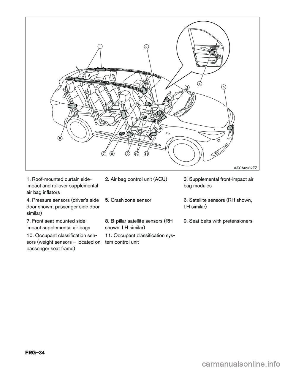
SRS Air Bag System Components Location
Avoid cutting air bag system parts. However, the vehicle can be cut (except inflators) under the following conditions:• The front, side and curtain air bags have deployed.
• At least three (3) minutes have passed after the 12V battery negative (-) cable has beendisconnected and the high voltage system has been shut down.
= Inflators (Peel back plastic trim parts prior to cutting operation to confirm exact inflator location.)
= Sensors
AAYIA0269ZZ
FRG–33
Page 34 of 44

1. Roof-mounted curtain side-
impact and rollover supplemental
air bag inflators2. Air bag control unit (ACU) 3. Supplemental front-impact air
bag modules
4. Pressure sensors (driver’s side
door shown; passenger side doorsimilar) 5. Crash zone sensor 6. Satellite sensors (RH shown,
LH similar)
7. Front seat-mounted side-
impact supplemental air bags 8. B-pillar satellite sensors (RH
shown, LH similar)9. Seat belts with pretensioners
10. Occupant classification sen-
sors (weight sensors – located on
passenger seat frame) 11. Occupant classification sys-
tem control unit
12
345
1110987
6
AAYIA0282ZZ
FRG–34
Page 35 of 44

Vehicle Cut Sheet
���
���
���
��
��
�
�
���
��
INFINITI Emergency Contact
1-800-662-6200 (US) or 1-800-361-4792 (Canada) Hours of Operation: 8am-5pm (Monday-Friday) Eastern, Central and Pacific Time Zones
High voltage component
or harness (Can be cut
only after the high voltage
system shut-down procedure has been completed.) Never cut electrical
components/batteries
for any reason. Death or serious personal injury will result. Traction Motor
July 2013
Traction Motor
Inverter
High voltage
harness
High voltage (Li-ion)
battery 12V
battery
12V Battery
Key
DANGER
voltage component
Nissan North America, Version (1)
NEVER CUT-High
AAYIA0069GB
FRG–35
Page 36 of 44

High Strength Steel Locations
= High strength steel
=
AAYIA0283ZZ
FRG–36
Page 37 of 44

3-3.5 Li-ion Battery Damage and Fluid Leaks
The Li-ion battery contains electrolyte solution. To avoid exposure to electrolyte solution
and serious personal injury, always wear appropriate solvent resistant Personal Protective
Equipment (PPE) and read the following precautions:
• Electrolyte solution is a skin irritant.
• Electrolyte solution is an eye irritant – If contact with eyes, rinse with plenty of water andsee a doctor immediately.
• If electrolyte leak occurs, wear appropriate solvent resistant PPE and use a dry cloth to clean up the spilled electrolyte. Be sure to adequately ventilate the area.
• Electrolyte solution is highly flammable
• Electrolyte liquid or fumes that have come into contact with water vapors in the air will create an oxidized substance. This substance may irritate skin and eyes. In these cases,
rinse with plenty of water and see a doctor immediately.
• Electrolyte fumes (when inhaled) can cause respiratory irritation and acute intoxication. Move to fresh air and wash mouth with water. See a doctor immediately.
If electrolyte solution leakage, or damage such as any problem with the Li-ion battery casing are observed,
first responders should attempt to neutralize the battery by applying a large volume of water to the battery
pack while wearing appropriate Personal Protective Equipment (PPE) . The neutralization process helps
stabilize the thermal condition of the battery pack but does not discharge the battery.
Li-ion Battery Electrolyte Solution Characteristics: • Clear in color
• Sweet odor
• Similar viscosity to water
• Since the Li-ion battery is made up of many small sealed battery modules, electrolyte solution
leakage should be minimal.
NOTE:
Other fluids in the vehicle (such as engine oil, washer fluid, brake fluid, coolant, etc.) are
the same as those in a conventional vehicle.
FRG–37
Page 38 of 44

3-3.6 Accessing the Occupants1. Remove windowsa. Perform window removal the same as a normal vehicle.
2. Remove doors a. The doors are removable with hand tools or basic rescue tools such as electrical/hydraulicrescue tools. It may be easier to remove the doors by cutting door hinges.
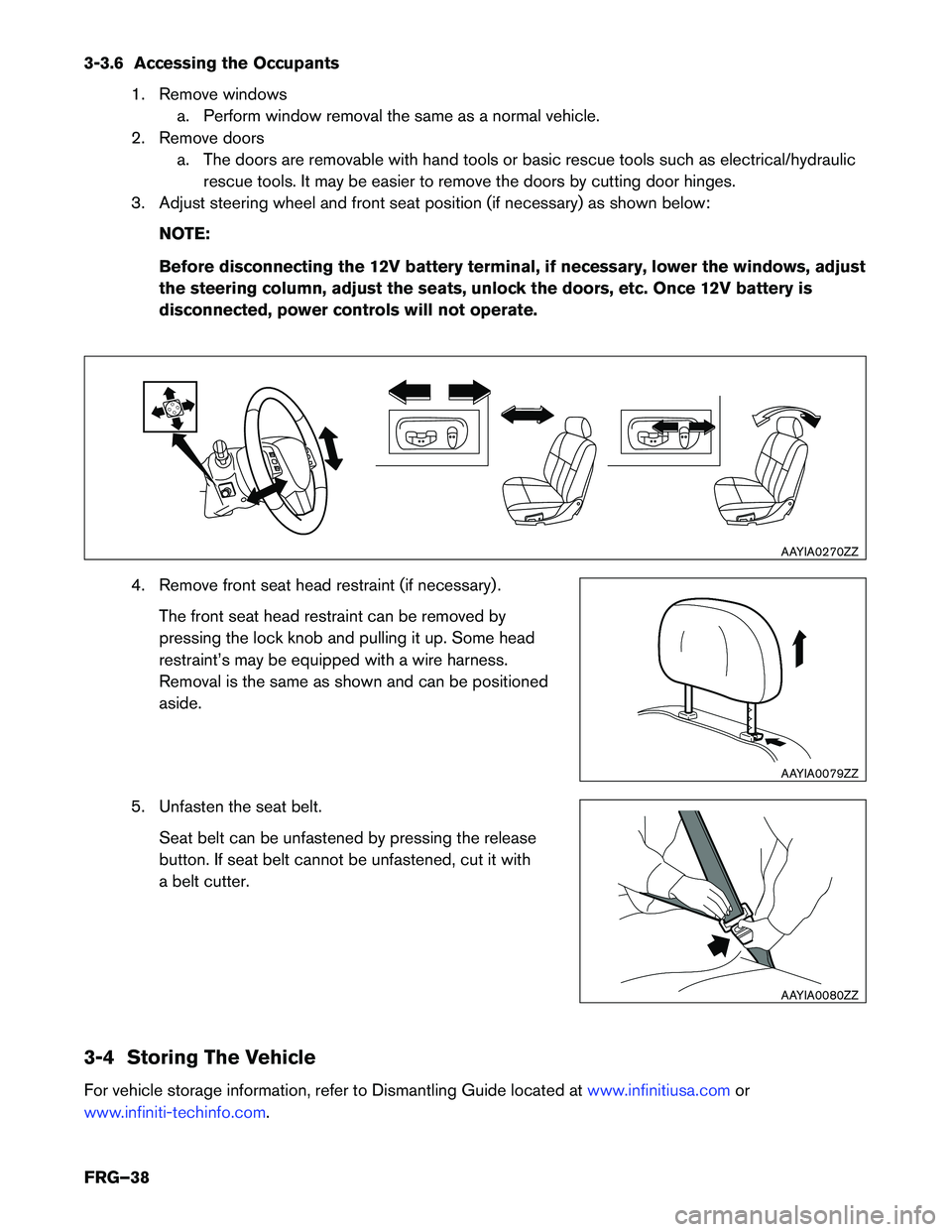
3. Adjust steering wheel and front seat position (if necessary) as shown below:
NOTE:
Before disconnecting the 12V battery terminal, if necessary, lower the windows, adjust
the steering column, adjust the seats, unlock the doors, etc. Once 12V battery is
disconnected, power controls will not operate.
4. Remove front seat head restraint (if necessary) . The front seat head restraint can be removed by
pressing the lock knob and pulling it up. Some head
restraint’s may be equipped with a wire harness.
Removal is the same as shown and can be positionedaside.
5. Unfasten the seat belt. Seat belt can be unfastened by pressing the release
button. If seat belt cannot be unfastened, cut it with
a belt cutter.
3-4 Storing The Vehicle
For vehicle storage information, refer to Dismantling Guide located at
www.infinitiusa.comor
www.infiniti-techinfo.com.
AAYIA0270ZZ
AAYIA0079ZZ
AAYIA0080ZZ
FRG–38
Page 39 of 44

4. Emergency Quick Reference Guide
The following is for emergency quick reference only. It does not replace the detailed safety information and
procedures in this manual.FRG–39
Page 40 of 44
