wheel INFINITI QX80 2019 Owner's Guide
[x] Cancel search | Manufacturer: INFINITI, Model Year: 2019, Model line: QX80, Model: INFINITI QX80 2019Pages: 524, PDF Size: 2.45 MB
Page 113 of 524

Vehicle Dynamic Control
(VDC) off indicator light
When the ignition switch is in the ON
position, the Vehicle Dynamic Control
(VDC) off indicator light illuminates and then
turns off.
The light comes on when the vehicle dynamic
control off switch is pushed to OFF. This
indicates that the vehicle dynamic control
system is not operating.
When the 4L position is selected with the
Four-Wheel Drive (4WD) shift switch, the
VDC system is disabled and the VDC off
indicator light illuminates. (4WD models)
For additional information, see “Vehicle
Dynamic Control (VDC) system” (P.5-133).
AUDIBLE REMINDERS
Key reminder chime
A chime will sound if the driver side door is
opened while the ignition switch is pushed to
the ACC position. Make sure the ignition
switch is pushed to the OFF position, and
take the Intelligent Key with you when
leaving the vehicle.
Light reminder chime
A chime will sound when the driver side door
is opened with the light switch in theorposition and the ignition switch in the
ACC, OFF or LOCK position.
Turn the light switch off when you leave the
vehicle.
Parking brake reminder chime
The chime will sound if the vehicle is driven
at more than 4 MPH (7 km/h) with the
parking brake applied. Stop the vehicle and
release the parking brake.
Brake pad wear warning
The disc brake pads have audible wear
warnings. When a brake pad requires repla-
cement, it will make a high pitched scraping
sound when the vehicle is in motion. This
scraping sound will first occur only when the
brake pedal is depressed. After more wear of
the brake pad, the sound will always be
heard even if the brake pedal is not
depressed. Have the brakes checked as soon
as possible if the warning sound is heard.
SIC4379
The vehicle information displaylocated
between the speedometer and odometer,
and shows the indicators for the driving
systems, Intelligent Key operation and var-
ious warnings and information.
For detailed information about each system,
see the following sections:
. Automatic Transmission (AT)
— “Warning lights, indicator lights and audible reminders” (P.2-11).
— “Driving the vehicle” (P.5-17).
. Four-Wheel Drive (4WD) system
— “INFINITI all-mode 4WD
®” (P.5-120).
. Back-up Collision Intervention (BCI) sys-
tem
Instruments and controls2-21
VEHICLE INFORMATION DISPLAY
Page 118 of 524

2-26Instruments and controls
.Forward Emergency Braking (FEB) with
pedestrian detection system
. Predictive Forward Collision Warning
(PFCW) system
For more details, see “Intelligent Cruise
Control (ICC)” (P.5-66), “Distance Control
Assist (DCA)” (P.5-87), “Forward Emer-
gency Braking (FEB) with pedestrian detec-
tion” (P.5-100) or “Predictive Forward
Collision Warning (PFCW)” (P.5-110).
19. “TIMER” indicator
This indicator appears when the set “TIMER”
indicator activates. You can set the time for
up to 6 hours. (See “Trip computer” (P.2-
28).)
20. Low outside temperature
warning
This warning appears if the outside tem-
perature is below 37°F (3°C). The warning
can be set not to be displayed. (See “Trip
computer” (P.2-28).)
21. Four-Wheel Drive (4WD) shift
indicator (4WD models)
This indicator shows the Four-Wheel Drive
(4WD) driving mode (AUTO, 4HI or 4LO)
that is selected by the 4WD shift switch.
(See “INFINITI all-mode 4WD
®” (P.5-120).)
22. Intelligent Cruise Control (ICC)
system MAIN switch indicator (if so
equipped)
The Intelligent Cruise Control (ICC) system
main switch indicator (CRUISE) is displayed
when the ICC main switch is pushed. When
the main switch is pushed again, the indi-
cator disappears. While the CRUISE indica-
tor is displayed, the ICC system is
operational.
The cruise control set indicator (SET) is
displayed while the vehicle is controlled by
the conventional (fixed speed) cruise control
mode of the ICC system.
For more details, see “Intelligent Cruise
Control (ICC)” (P.5-66).
23. Distance Control Assist (DCA)
system switch indicator (if so
equipped)
The indicator is displayed when the Distance
Control Assist (DCA) system switch is
pushed on. When the switch is pushed again,
the indicator disappears. While the indicator
is displayed, the DCA system is operational.
(See “Distance Control Assist (DCA)” (P.5-
87) .)
24. Back-up Collision Intervention
(BCI) system indicator (if so
equipped)
The BCI ON indicator (SYSTEM ON) ap-
pears when the shift lever is in the R
(Reverse) position with the Back-up Collision
Intervention (BCI) system turned on.
If the BCI system is turned off, the BCI OFF
indicator (SYSTEM OFF) appears.
For more details, see “Back-up Collision
Intervention (BCI)” (P.5-55).
Page 119 of 524

SIC4325
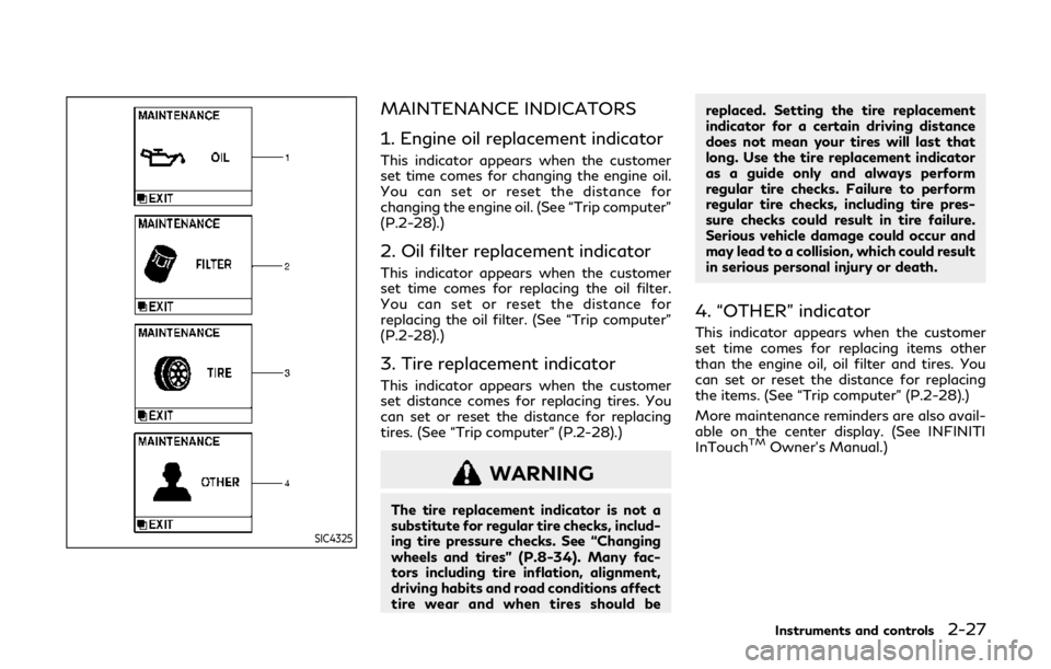
MAINTENANCE INDICATORS
1. Engine oil replacement indicator
This indicator appears when the customer
set time comes for changing the engine oil.
You can set or reset the distance for
changing the engine oil. (See “Trip computer”
(P.2-28).)
2. Oil filter replacement indicator
This indicator appears when the customer
set time comes for replacing the oil filter.
You can set or reset the distance for
replacing the oil filter. (See “Trip computer”
(P.2-28).)
3. Tire replacement indicator
This indicator appears when the customer
set distance comes for replacing tires. You
can set or reset the distance for replacing
tires. (See “Trip computer” (P.2-28).)
WARNING
The tire replacement indicator is not a
substitute for regular tire checks, includ-
ing tire pressure checks. See “Changing
wheels and tires” (P.8-34). Many fac-
tors including tire inflation, alignment,
driving habits and road conditions affect
tire wear and when tires should bereplaced. Setting the tire replacement
indicator for a certain driving distance
does not mean your tires will last that
long. Use the tire replacement indicator
as a guide only and always perform
regular tire checks. Failure to perform
regular tire checks, including tire pres-
sure checks could result in tire failure.
Serious vehicle damage could occur and
may lead to a collision, which could result
in serious personal injury or death.
4. “OTHER” indicator
This indicator appears when the customer
set time comes for replacing items other
than the engine oil, oil filter and tires. You
can set or reset the distance for replacing
the items. (See “Trip computer” (P.2-28).)
More maintenance reminders are also avail-
able on the center display. (See INFINITI
InTouch
TMOwner’s Manual.)
Instruments and controls2-27
Page 131 of 524

High beam assist
The high beam assist system will operate
when the vehicle is driven at speeds of
approximately 22 MPH (35 km/h) and
above. If an oncoming vehicle or leading
vehicle appears in front of your vehicle when
the headlight high beam is on, the headlight
will be switched to the low beam automa-
tically.
Precautions on high beam assist:
WARNING
.The high beam assist system is a
convenience but it is not a substitute
for safe driving operation. The driver
should remain alert at all times,
ensure safe driving practices and
switch the high beams and low beam
manually when necessary.
. The high beam or low beam may not
switch automatically under the fol-
lowing conditions. Switch the high
beam and low beam manually.
— During bad weather (rain, fog, snow, wind, etc.).
— When a light source similar to a headlight or tail light is in the
vicinity of the vehicle. — When the headlights of the on-
coming vehicle or the leading
vehicle are turned off, when the
color of the light is affected due to
foreign materials on the lights, or
when the light beam is out of
position.
— When there is a sudden, contin- uous change in brightness.
— When driving on a road that passes over rolling hills, or a road
that has level differences.
— When driving on a road with many curves.
— When a sign or mirror-like sur- face is reflecting intense light
towards the front of the vehicle.
— When the container, etc. being towed by a leading vehicle is
reflecting intense light.
— When a headlight on your vehicle is damaged or dirty.
— When the vehicle is leaning at an angle due to a punctured tire,
being towed, etc.
. The timing of switching the low beam
and high beam may change under the
following situations. — The brightness of the headlights
of the oncoming vehicle or leading
vehicle.
— The movement and direction of the oncoming vehicle and the
leading vehicle.
— When only one light on the on- coming vehicle or the leading
vehicle is illuminated.
— When the oncoming vehicle or the leading vehicle is a two-wheeled
vehicle.
— Road conditions (incline, curve, the road surface, etc.).
— The number of passengers and the amount of luggage.
Instruments and controls2-39
Page 134 of 524

2-42Instruments and controls
Daytime running light system
The daytime running lights automatically
illuminate when the engine is started with
the parking brake released. The daytime
running lights operate with the headlight
switch in the OFF position or in the
position. Turn the headlight switch to theposition for full illumination when driv-
ing at night.
If the parking brake is applied before the
engine is started, the daytime running lights
do not illuminate. The daytime running lights
illuminate once the parking brake is released.
The daytime running lights will remain on
until the ignition switch is pushed to the OFF
position.
WARNING
When the daytime running light system
is active, tail lights on your vehicle are
not on. It is necessary at dusk to turn on
your headlights. Failure to do so could
cause an accident injuring yourself and
others.
Adaptive Front lighting System
(AFS) (if so equipped)
The Adaptive Front lighting System (AFS) will automatically adjust the headlights (low
beam) toward the turning direction to
improve the driver’s view. When the head-
light switch is ON and the driver operates
the steering wheel in a turn, the AFS system
will be activated.
The AFS will operate:
.
when the headlight switch is ON.
. when the shift lever is in any position
other than P (Park) or R (Reverse).
. when the vehicle is driven at above 3
MPH (5 km/h) for the left-side head-
light. Note that the right-side low beam
headlight will swivel but the left-side
headlight will not swivel when the vehicle
is below 3 MPH (5 km/h) and the
steering wheel is turned.
AFS will also adjust the headlight to a proper
axis automatically, depending on the number
of occupants in the vehicle, the load the
vehicle is carrying and the road conditions.
If the AFS OFF indicator light blinks after
the ignition switch has been pushed to the
ON position, this may indicate that the AFS
is not functioning properly. Have the system
checked. It is recommended you visit an
INFINITI retailer for this service. When the
engine is started, the headlights will vibrate
to check the system condition. This is not a
malfunction.
HEADLIGHT WASHER (if so
equipped)
The headlight washer operates when the
headlight is on and the ignition switch is in
the ON position.
Pull the windshield washer switch toward
you. The headlight washer operates with the
windshield washer operation. This operation
activates once each time either the ignition
switch or the headlight switch is turned off
and on.
After the first operation, the headlight
washer operates once at every fifth opera-
tion of the windshield washer.
CAUTION
. Do not operate the washer continu-
ously for longer than 30 seconds.
. Do not operate the headlight washer
if the window washer fluid reservoir
is empty.
Page 137 of 524

JVI0395X
The heated steering wheel system is de-
signed to operate only when the surface
temperature of the steering wheel is below
68°F (20°C).
Push the heated steering wheel switch to
warm the steering wheel after the engine
starts. The indicator light
on the switch
will illuminate.
If the surface temperature of the steering
wheel is below 68°F (20°C), the system will
heat the steering wheel and cycle off and on
to maintain a temperature above 68°F
(20°C). The indicator light will remain on as
long as the system is on.
Push the switch again to turn the heated
steering wheel system off manually. The indicator light will turn off.
NOTE:
If the surface temperature of the steering
wheel is above 68°F (20°C) when the switch
is turned on, the system will not heat the
steering wheel. This is not a malfunction.
SIC4444
To sound the horn, push the center pad area
of the steering wheel.
WARNING
Do not disassemble the horn. Doing so
could affect proper operation of the
supplemental front air bag system. Tam-
pering with the supplemental front air
bag system may result in serious perso-
nal injury.
Instruments and controls2-45
HEATED STEERING WHEEL
HORN
Page 141 of 524

SSD0956
The warning systems switch is used to turn
on and off the warning systems (Lane
Departure Warning (LDW) and Blind Spot
Warning (BSW) systems) that are activated
using the settings menu on the center
display.
When the warning systems switch is turned
off, the indicator
on the switch is off. The
indicator will also be off if all of the warning
systems are deactivated using the settings
menu.
The LDW system will sound a warning chime
and blink the Lane Departure Warning
(LDW) indicator light (orange) to alert the
driver if the vehicle is traveling close to either
the left or the right of a traveling lane with detectable lane markers. (See “Lane Depar-
ture Warning (LDW)/Lane Departure Pre-
vention (LDP) ” (P.5-22).)
The BSW system will turn on the side
indicator lights, located next to the outside
mirrors, if the radar sensors detect a vehicle
in the detection zone. If the turn signal is
activated in the direction of the detected
vehicle, a chime sounds twice and the side
indicator light will flash. (See “Blind Spot
Warning (BSW)” (P.5-32).)
SIC4454
For driving or starting the vehicle on snowy
roads or slippery areas, push on the SNOW
mode switch. The SNOW mode indicator
light will illuminate. When the SNOW mode
is activated, engine output is controlled to
avoid wheel spin.
Push off the SNOW mode for normal
driving.
Instruments and controls2-49
WARNING SYSTEMS SWITCH (if
so equipped)
SNOW MODE SWITCH
Page 142 of 524

2-50Instruments and controls
SIC4474
TOW mode should be used when pulling a
heavy trailer or hauling a heavy load. Driving
the vehicle in TOW mode with no trailer/
load or light trailer/light load will not cause
any damage. However, fuel economy may be
reduced, and the transmission/engine driv-
ing characteristics may feel unusual.
Push the TOW mode switch to activate
TOW mode. The indicator light on the TOW
mode switch illuminates when TOW mode is
selected. Push the TOW mode switch again
to turn TOW mode off.
TOW mode is automatically canceled when
the ignition switch is placed in the OFF
position.
SIC4455
The vehicle should be driven with the Vehicle
Dynamic Control (VDC) system on for most
driving conditions.
If the vehicle is stuck in mud or snow, the
VDC system reduces the engine output to
reduce wheel spin. The engine speed will be
reduced even if the accelerator is depressed
to the floor. If maximum engine power is
needed to free a stuck vehicle, turn the VDC
system off.
To turn off the VDC system, push the VDC
OFF switch. The
indicator will illumi-
nate.
Push the VDC OFF switch again or restart
the engine to turn on the system. (See
“Vehicle Dynamic Control (VDC) system” (P.5-133).)
TOW MODE SWITCH
VEHICLE DYNAMIC CONTROL
(VDC) OFF SWITCH
Page 199 of 524

longer than 1 second to turn off the
LOOSE FUEL CAP warning after tigh-
tening the fuel cap.WARNING
.Do not adjust the steering wheel
while driving. You could lose control
of your vehicle and cause an accident.
. Do not adjust the steering wheel any
closer to you than is necessary for
proper steering operation and com-
fort. The driver’s air bag inflates with
great force. If you are unrestrained,
leaning forward, sitting sideways or
out of position in any way, you are at
greater risk of injury or death in a
crash. You may also receive serious or
fatal injuries from the air bag if you
are up against it when it inflates.
Always sit back against the seatback
and as far away as practical from the
steering wheel. Always use the seat
belts.
SPA2754
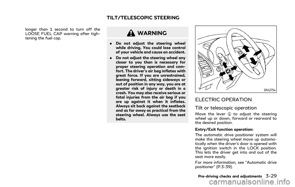
ELECTRIC OPERATION
Tilt or telescopic operation
Move the leverto adjust the steering
wheel up or down, forward or rearward to
the desired position.
Entry/Exit function operation:
The automatic drive positioner system will
make the steering wheel move up automa-
tically when the driver’s door is opened with
the ignition switch in the LOCK position.
This lets the driver get into and out of the
seat more easily.
For more information, see “Automatic drive
positioner” (P.3-39).
Pre-driving checks and adjustments3-29
TILT/TELESCOPIC STEERING
Page 209 of 524

SIC4448
VANITY MIRROR
To use the front vanity mirror, pull down the
sun visor and pull up the cover.
JVP0250X
SET/memory switches
The automatic drive positioner system has
three features:
. Entry/exit function
. Memory storage
. Setting memory function
ENTRY/EXIT FUNCTION
This system is designed so that the driver’s
seat and steering column will automatically
move when the automatic transmission shift
lever is in the P (Park) position. This allows
the driver to get into and out of the driver’s
seat more easily.
The driver’s seat will slide backward and the
steering wheel will move up when the
driver’s door is opened with the ignition
switch in the LOCK position.
The driver’s seat and steering wheel will
return to the previous positions when the
ignition switch is pushed to the ACC posi-
tion.
The driver’s seat will not return to the
previous positions if the seat or steering
adjusting switch is operated when the seat is
at the exit position.
Cancel or activate entry/exit func-
tion
The shift lever must be in the P (Park)
position with the ignition switch in the OFF
position.
The entry/exit function can be activated or
canceled by pressing and holding the SET
switch for more than 10 seconds.
The entry/exit function can also be acti-
vated or canceled if the “Lift Steering Wheel
Pre-driving checks and adjustments3-39
AUTOMATIC DRIVE POSITIONER