seat adjustment INFINITI QX80 2020 User Guide
[x] Cancel search | Manufacturer: INFINITI, Model Year: 2020, Model line: QX80, Model: INFINITI QX80 2020Pages: 516, PDF Size: 1.89 MB
Page 65 of 516

Installing top tether strap
First, secure the child restraint with the
LATCH lower anchors (2nd row captain’s
or bench outboard seating positions only).
1. If necessary, raise or remove the headrestraint or headrest to position the top
tether strap over the top of the seatback.
If the head restraint or headrest is
removed, store it in a secure place. Be
sure to reinstall the head restraint or
headrest when the child restraint is
removed. See “Head restraints/head-
rests” (P.1-13) for head restraint or
headrest adjustment, removal and in-
stallation information.
2. Secure the tether strap to the tether anchor point on the back of each seat-
back behind the child restraint.
3. Tighten the tether strap according to the manufacturer’s instructions to remove
any slack. Make sure the head restraint
or headrest does not contact the top
tether strap.
If you have any questions when installing a
top tether strap on the rear seat, it is
recommended you visit an INFINITI retailer
for this service.
FORWARD-FACING CHILD RE-
STRAINT INSTALLATION USING
THE SEAT BELTS
WARNING
. The three-point seat belt with Auto-
matic Locking Retractor (ALR) must
be used when installing a child re-
straint. Failure to use the ALR mode
will result in the child restraint not
being properly secured. The restraint
could tip over or be loose and cause
injury to a child in a sudden stop or
collision. Also, it can change the
operation of the front passenger air
bag. See “Front passenger air bag
and status light” (P.1-59)
. When installing a child restraint sys-
tem in the 3rd center position, both
the center seat belt connector tongue
and buckle tongue must be secured.
See “3rd row center seat belt” (P.1-
24).
SSS0640
Forward-facing (front passenger seat) —
step 1
Refer to all Warnings and Cautions in the
“Child safety” and “Child restraints” sections
before installing a child restraint.
Do not use the lower anchors if the com-
bined weight of the child and the child
restraint exceeds 65 lbs (29.5 kg). If the
combined weight of the child and the child
restraint is greater than 65 lbs (29.5 kg), use
the vehicle’s seat belt (not the lower an-
chors) to install the child restraint. Be sure to
follow the child restraint manufacturer’s
instructions for installation.
Follow these steps to install a forward-
facing child restraint using the vehicle seat
belt in the rear seats or in the front
Safety — seats, seat belts and supplemental restraint system1-43
Page 66 of 516

1-44Safety — seats, seat belts and supplemental restraint system
passenger seat:
1.If you must install a child restraint in the
front seat, it should be placed in a
forward-facing direction only. Move
the seat to the rearmost position. Child
restraints for infants must be used in the
rear-facing direction and, therefore,
must not be used in the front seat.
2. Position the child restraint on the seat. Always follow the child restraint manu-
facturer’s instructions.
The back of the child restraint should be
secured against the vehicle seatback.
If necessary, adjust or remove the head
restraint or headrest to obtain the
correct child restraint fit. If the head
restraint or headrest is removed, store it
in a secure place. Be sure to reinstall the
head restraint or headrest when the
child restraint is removed. See “Head
restraints/headrests” (P.1-13) for head
restraint or headrest adjustment, re-
moval and installation information.
If the seating position does not have an
adjustable head restraint or a headrest
and it is interfering with the proper child
restraint fit, try another seating position
or a different child restraint.
SSS0360B
Forward-facing — step 3
3. Route the seat belt tongue through the child restraint and insert it into the buckle
until you hear and feel the latch engage.
Be sure to follow the child restraint
manufacturer’s instructions for belt
routing.
If the child restraint is equipped with a
top tether strap, route the top tether
strap and secure the tether strap to the
tether anchor point (rear seat installation
only). See “Installing top tether strap”
(P.1-47). Do not install child restraints
that require the use of a top tether strap
in seating positions that do not have a
top tether anchor.
SSS0651
Forward-facing — step 4
4. Pull the shoulder belt until the belt is fully extended. At this time, the seat belt
retractor is in the Automatic Locking
Retractor (ALR) mode (child restraint
mode). It reverts to Emergency Locking
Retractor (ELR) mode when the seat belt
is fully retracted.
Page 69 of 516
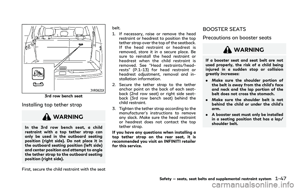
JVR0621X
3rd row bench seat
Installing top tether strap
WARNING
In the 3rd row bench seat, a child
restraint with a top tether strap can
only be used in the outboard seating
position (right side). Do not place it in
the outboard seating position (left side)
and center position and attempt to angle
the tether strap to the outboard seating
position (right side).
First, secure the child restraint with the seat belt.
1. If necessary, raise or remove the head
restraint or headrest to position the top
tether strap over the top of the seatback.
If the head restraint or headrest is
removed, store it in a secure place. Be
sure to reinstall the head restraint or
headrest when the child restraint is
removed. See “Head restraints/head-
rests” (P.1-13) for head restraint or
headrest adjustment, removal and in-
stallation information.
2. Secure the tether strap to the tether anchor point on the back of each seat-
back (2nd row seat) or right side seat-
back (3rd row bench seat) behind the
child restraint.
3. Tighten the tether strap according to the manufacturer’s instructions to remove
any slack. Make sure the head restraint
or headrest does not contact the top
tether strap.
If you have any questions when installing a
top tether strap on the rear seat, it is
recommended you visit an INFINITI retailer
for this service.
BOOSTER SEATS
Precautions on booster seats
WARNING
If a booster seat and seat belt are not
used properly, the risk of a child being
injured in a sudden stop or collision
greatly increases:
. Make sure the shoulder portion of
the belt is away from the child’s face
and neck and the lap portion of the
belt does not cross the stomach.
. Make sure the shoulder belt is not
behind the child or under the child’s
arm.
. A booster seat must only be installed
in a seating position that has a lap/
shoulder belt.
Safety — seats, seat belts and supplemental restraint system1-47
Page 70 of 516
1-48Safety — seats, seat belts and supplemental restraint system
LRS0455
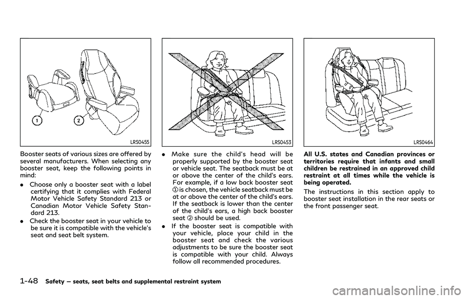
Booster seats of various sizes are offered by
several manufacturers. When selecting any
booster seat, keep the following points in
mind:
.Choose only a booster seat with a label
certifying that it complies with Federal
Motor Vehicle Safety Standard 213 or
Canadian Motor Vehicle Safety Stan-
dard 213.
. Check the booster seat in your vehicle to
be sure it is compatible with the vehicle’s
seat and seat belt system.
LRS0453
. Make sure the child’s head will be
properly supported by the booster seat
or vehicle seat. The seatback must be at
or above the center of the child’s ears.
For example, if a low back booster seat
is chosen, the vehicle seatback must be
at or above the center of the child’s ears.
If the seatback is lower than the center
of the child’s ears, a high back booster
seat
should be used.
. If the booster seat is compatible with
your vehicle, place your child in the
booster seat and check the various
adjustments to be sure the booster seat
is compatible with your child. Always
follow all recommended procedures.
LRS0464
All U.S. states and Canadian provinces or
territories require that infants and small
children be restrained in an approved child
restraint at all times while the vehicle is
being operated.
The instructions in this section apply to
booster seat installation in the rear seats or
the front passenger seat.
Page 71 of 516

Booster seat installation
CAUTION
Do not use the lap/shoulder belt Auto-
matic Locking Retractor (ALR) mode
when using a booster seat with the seat
belts.
Refer to all Warnings and Cautions in the
“Child safety”, “Child restraints” and “Boos-
ter seats” sections earlier in this section
before installing a child restraint.
Follow these steps to install a booster seat in
the rear seat or in the front passenger seat:
SSS0640
1. If you must install a booster seat in the
front seat, move the seat to the rear-
most position.
2. Position the booster seat on the seat. Only place it in a forward-facing direc-
tion. Always follow the booster seat
manufacturer’s instructions.
LRS0454
Front passenger position
3. The booster seat should be positioned on the vehicle seat so that it is stable.
If necessary, adjust or remove the head
restraint or headrest to obtain the
correct booster seat fit. If the head
restraint or headrest is removed, store
it in a secure place. Be sure to reinstall
the head restraint or headrest when the
booster seat is removed. See “Head
restraints/headrests” (P.1-13) for head
restraint or headrest adjustment, re-
moval and installation information.
If the seating position does not have an
adjustable head restraint or a headrest
and it is interfering with the proper
Safety — seats, seat belts and supplemental restraint system1-49
Page 178 of 516
3-4Pre-driving checks and adjustments
VALET HAND-OFF
When you have to leave a key with a valet,
give them the Intelligent Key itself and keep
the mechanical key with you to protect your
belongings.
To prevent the glove box from being opened
during valet hand-off, follow the procedures
below.
1. Remove the mechanical key from theIntelligent Key.
2. Lock the glove box with the mechanical key.
3. Hand the Intelligent Key to the valet, keeping the mechanical key in your
pocket or bag for insertion into the
Intelligent Key when you retrieve your
vehicle.
See “Storage” (P.2-57).WARNING
. Always have the doors locked while
driving. Along with the use of seat
belts, this provides greater safety in
the event of an accident by helping to
prevent persons from being thrown
from the vehicle. This also helps keep
children and others from unintention-
ally opening the doors, and will help
keep out intruders.
. Before opening any door, always look
for and avoid oncoming traffic.
. To help avoid risk of injury or death
through unintended operation of the
vehicle and or its systems, including
entrapment in windows or inadver-
tent door lock activation, do not
leave children, people who require
the assistance of others or pets
unattended in your vehicle. Addition-
ally, the temperature inside a closed
vehicle on a warm day can quickly
become high enough to cause a sig-
nificant risk of injury or death to
people and pets.
SPA2457B
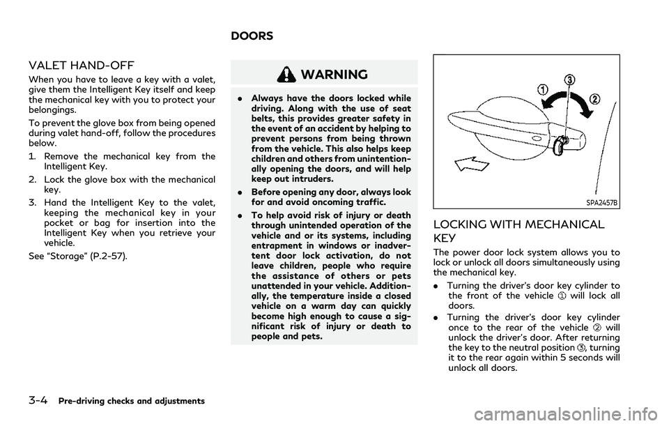
LOCKING WITH MECHANICAL
KEY
The power door lock system allows you to
lock or unlock all doors simultaneously using
the mechanical key.
.Turning the driver’s door key cylinder to
the front of the vehicle
will lock all
doors.
. Turning the driver’s door key cylinder
once to the rear of the vehicle
will
unlock the driver’s door. After returning
the key to the neutral position
, turning
it to the rear again within 5 seconds will
unlock all doors.
DOORS
Page 203 of 516
WARNING
.Do not adjust the steering wheel
while driving. You could lose control
of your vehicle and cause an accident.
. Do not adjust the steering wheel any
closer to you than is necessary for
proper steering operation and com-
fort. The driver’s air bag inflates with
great force. If you are unrestrained,
leaning forward, sitting sideways or
out of position in any way, you are at
greater risk of injury or death in a
crash. You may also receive serious or
fatal injuries from the air bag if you
are up against it when it inflates.
Always sit back against the seatback
and as far away as practical from the
steering wheel. Always use the seat
belts.
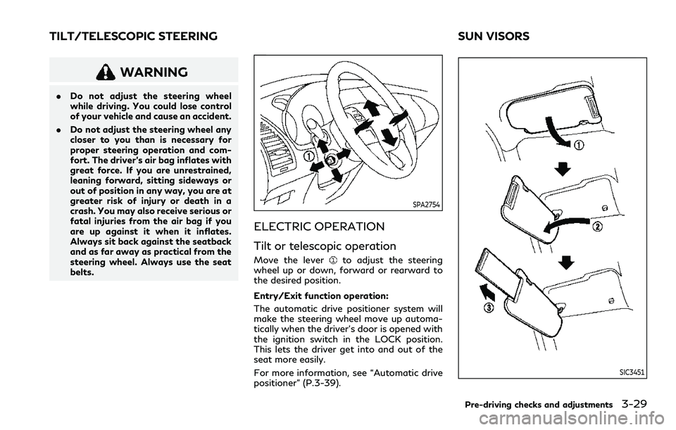
SPA2754
ELECTRIC OPERATION
Tilt or telescopic operation
Move the leverto adjust the steering
wheel up or down, forward or rearward to
the desired position.
Entry/Exit function operation:
The automatic drive positioner system will
make the steering wheel move up automa-
tically when the driver’s door is opened with
the ignition switch in the LOCK position.
This lets the driver get into and out of the
seat more easily.
For more information, see “Automatic drive
positioner” (P.3-39).
SIC3451
Pre-driving checks and adjustments3-29
TILT/TELESCOPIC STEERING SUN VISORS
Page 205 of 516
dicator light will turn off. Push the “I” switchto turn the system on.
Do not allow any object to cover the sensors
or apply glass cleaner on them. Doing so
will reduce the sensitivity of the sensor,
resulting in improper operation.
For the HomeLink
®Universal Transceiver
operation, see “HomeLink®Universal Trans-
ceiver (Type A)” (P.2-71).
Smart Rearview Mirror (if so
equipped)
WARNING
. Failure to follow the warnings and
instructions for proper use of the
Smart Rearview Mirror could result
in serious injury or death.
— The Smart Rearview Mirror is a convenience feature but it is not a
substitute for proper vehicle op-
eration. The system has areas
where objects cannot be viewed.
Check the blind spot of the Smart
Rearview Mirror before vehicle
operation. The driver is always
responsible for safe driving.
— Do not disassemble or modify the Smart Rearview Mirror, the cam- era unit or wirings. If you do, it
may result in accidents or fire. In
case you notice smoke or smell
coming from the Smart Rearview
Mirror, stop using the system
immediately. It is recommended
that you see an INFINITI retailer
for servicing.
— Do not operate the Smart Rear- view Mirror while driving. Doing
so can be a distraction and it could
lose control of your vehicle and
cause an accident or serious in-
jury.
— Do not gaze into the Smart Rear- view Mirror display during driv-
ing. It may cause a distraction and
it could lose control of your vehi-
cle and cause an accident or
serious injury.
— Do not put a cigarette or flames to the Smart Rearview Mirror, the
camera unit or wirings. It may
cause a fire.
. Be sure to adjust the Smart Rearview
Mirror before driving. Switch the
system to the conventional rearview
mirror mode and be properly seated
on the driver’s seat. Then adjust the
mirror so as to see the rear window properly. Driving without adjusting
the mirror may cause difficulty in
watching the display at Smart Rear-
view Mirror mode (camera view
mode) due to the reflection from the
surface of the mirror.
. If the Smart Rearview Mirror mal-
functions, immediately switch the
system to the conventional rearview
mirror mode.
. When strong light (for example, sun-
light or high beams from following
vehicles) enters the camera, a light
beam or a glaring light may appear on
the monitor screen of the Smart
Rearview Mirror. In that case, switch
the system to the conventional rear-
view mirror mode appropriately.
. If dirt, rain or snow accumulates on
the exterior glass surface covering
the camera, the Smart Rearview
Mirror may not display objects
clearly. Use of the rear window
wiper/washer may improve visibility,
but if not, switch the Smart Rearview
Mirror to the conventional rearview
mirror mode until a time the glass
covering the camera can be cleaned.
Pre-driving checks and adjustments3-31
Page 213 of 516
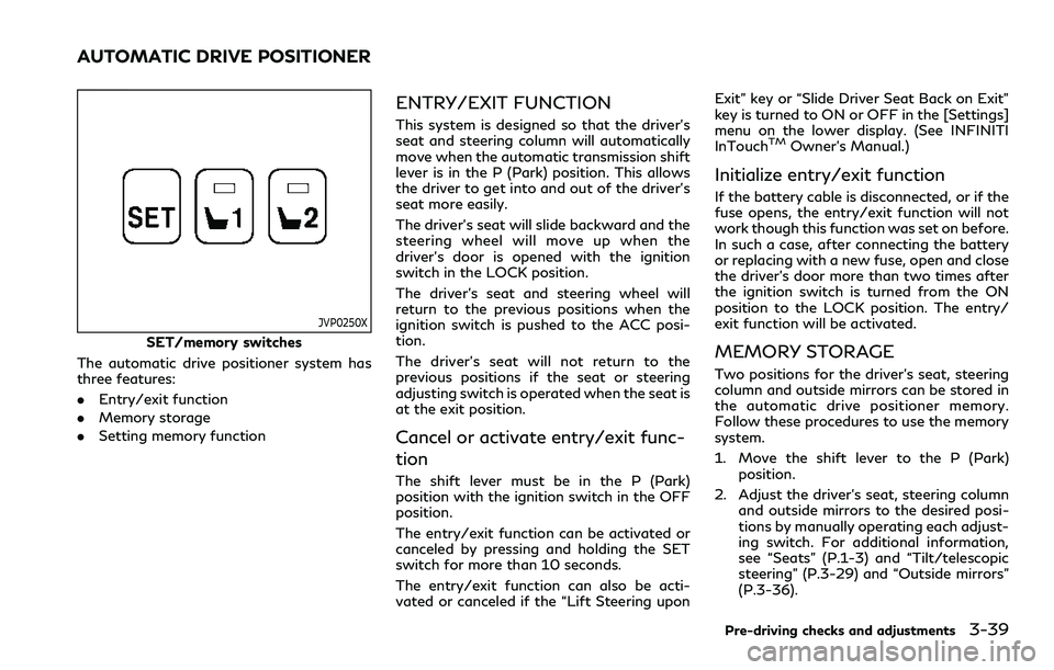
JVP0250X
SET/memory switches
The automatic drive positioner system has
three features:
. Entry/exit function
. Memory storage
. Setting memory function
ENTRY/EXIT FUNCTION
This system is designed so that the driver’s
seat and steering column will automatically
move when the automatic transmission shift
lever is in the P (Park) position. This allows
the driver to get into and out of the driver’s
seat more easily.
The driver’s seat will slide backward and the
steering wheel will move up when the
driver’s door is opened with the ignition
switch in the LOCK position.
The driver’s seat and steering wheel will
return to the previous positions when the
ignition switch is pushed to the ACC posi-
tion.
The driver’s seat will not return to the
previous positions if the seat or steering
adjusting switch is operated when the seat is
at the exit position.
Cancel or activate entry/exit func-
tion
The shift lever must be in the P (Park)
position with the ignition switch in the OFF
position.
The entry/exit function can be activated or
canceled by pressing and holding the SET
switch for more than 10 seconds.
The entry/exit function can also be acti-
vated or canceled if the “Lift Steering upon Exit” key or “Slide Driver Seat Back on Exit”
key is turned to ON or OFF in the [Settings]
menu on the lower display. (See INFINITI
InTouch
TMOwner’s Manual.)
Initialize entry/exit function
If the battery cable is disconnected, or if the
fuse opens, the entry/exit function will not
work though this function was set on before.
In such a case, after connecting the battery
or replacing with a new fuse, open and close
the driver’s door more than two times after
the ignition switch is turned from the ON
position to the LOCK position. The entry/
exit function will be activated.
MEMORY STORAGE
Two positions for the driver’s seat, steering
column and outside mirrors can be stored in
the automatic drive positioner memory.
Follow these procedures to use the memory
system.
1. Move the shift lever to the P (Park)
position.
2. Adjust the driver’s seat, steering column and outside mirrors to the desired posi-
tions by manually operating each adjust-
ing switch. For additional information,
see “Seats” (P.1-3) and “Tilt/telescopic
steering” (P.3-29) and “Outside mirrors”
(P.3-36).
Pre-driving checks and adjustments3-39
AUTOMATIC DRIVE POSITIONER
Page 214 of 516
3-40Pre-driving checks and adjustments
3. Push the SET switch and, within 5seconds, push the memory switch (1 or
2) fully for at least 1 second.
The indicator light for the pushed mem-
ory switch will stay on for approximately
5 seconds after pushing the switch.
When the memory is stored in the
memory switch (1 or 2), a buzzer will
sound.
If memory is stored in the same memory
switch, the previous memory will be
deleted.
Linking Intelligent Key to a stored
memory position
The Intelligent Key can be linked to a stored
memory position with the following proce-
dure.
1. Follow the steps for storing a memoryposition.
2. While the indicator light for the memory switch being set is illuminated for 5
seconds, push the
button on the
Intelligent Key. If the indicator light
blinks, the Intelligent Key is linked to
that memory setting.
Push the ignition switch to the OFF position,
and then push the
button on the
Intelligent Key. The driver’s seat, steering
wheel and outside mirrors will move to the memorized position.
Confirming memory storage
.
Push the ignition switch to the ON
position and push the SET switch. If the
main memory has not been stored, the
indicator light will come on for approxi-
mately 0.5 second. When the memory
has stored in position, the indicator light
will stay on for approximately 5 seconds.
. If the battery cable is disconnected, or if
the fuse opens, the memory will be
canceled. In this case, reset the desired
position using the previous procedure.
. If optional Intelligent Keys are added to
your vehicle, the memory storage proce-
dure to switch 1 or 2 and linking
Intelligent Key procedure to a stored
memory position should be performed
again for each Intelligent Key. For addi-
tional Intelligent Key information, see
“Keys” (P.3-2).
Selecting the memorized position
1. Move the shift lever to the P (Park) position.
2. Use one of the following methods to move the driver’s seat, the outside
mirrors and the steering wheel.
.Push the memory switch (1 or 2) fully
for at least 1 second. The driver’s seat, steering column and
outside mirrors will move to the memor-
ized position or to the exit position when
the entry/exit function is set to active
with the indicator light flashing, and then
the light will stay on for approximately 5
seconds.
SETTING MEMORY FUNCTION
The status of the following settings can be
linked to the Intelligent Key and the memor-
ized settings can be available for each
Intelligent Key.
.
Air conditioner system
. Navigation system
. Audio system
To use the memory function, lock the doors
with the Intelligent Key that is linked to the
settings.
To enable the memorized settings:
1. Carry the Intelligent Key that is linked to the settings, and unlock the doors by
pushing the driver’s door handle request
switch or “UNLOCK”
button on the
Intelligent Key.
2. Place the ignition switch in the ON position. The memorized settings are
available.