automatic transmission INFINITI QX80 2020 Owner's Manual
[x] Cancel search | Manufacturer: INFINITI, Model Year: 2020, Model line: QX80, Model: INFINITI QX80 2020Pages: 516, PDF Size: 1.89 MB
Page 21 of 516
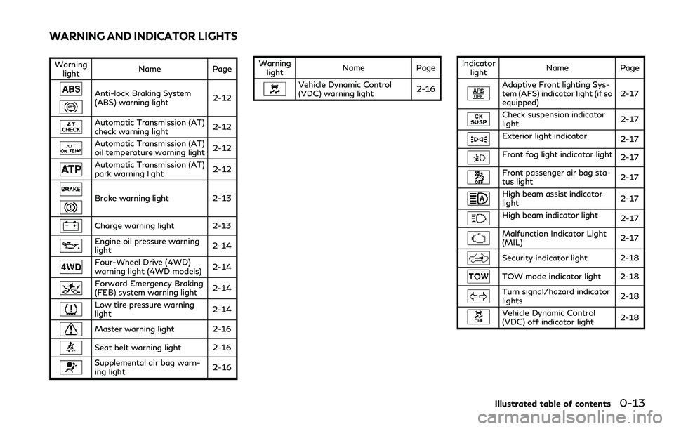
Warninglight Name Page
Anti-lock Braking System
(ABS) warning light
2-12
Automatic Transmission (AT)
check warning light2-12
Automatic Transmission (AT)
oil temperature warning light
2-12
Automatic Transmission (AT)
park warning light2-12
Brake warning light
2-13
Charge warning light 2-13
Engine oil pressure warning
light2-14
Four-Wheel Drive (4WD)
warning light (4WD models)
2-14
Forward Emergency Braking
(FEB) system warning light2-14
Low tire pressure warning
light
2-14
Master warning light 2-16
Seat belt warning light 2-16
Supplemental air bag warn-
ing light 2-16Warning
light Name Page
Vehicle Dynamic Control
(VDC) warning light 2-16Indicator
light Name PageAdaptive Front lighting Sys-
tem (AFS) indicator light (if so
equipped) 2-17
Check suspension indicator
light
2-17
Exterior light indicator
2-17
Front fog light indicator light2-17
Front passenger air bag sta-
tus light2-17
High beam assist indicator
light2-17
High beam indicator light
2-17
Malfunction Indicator Light
(MIL)2-17
Security indicator light 2-18
TOW mode indicator light 2-18
Turn signal/hazard indicator
lights
2-18
Vehicle Dynamic Control
(VDC) off indicator light2-18
Illustrated table of contents0-13
WARNING AND INDICATOR LIGHTS
Page 26 of 516

1-4Safety — seats, seat belts and supplemental restraint system
FRONT SEATS
Front power seat adjustment
Operating tips:
.The power seat motor has an auto-reset
overload protection circuit. If the motor
stops during operation, wait 30 seconds,
then reactivate the switch.
. Do not operate the power seat switch for
a long period of time when the engine is
off. This will discharge the battery.
See “Automatic drive positioner” (P.3-39)
for the seat position memory function.
CAUTION
When adjusting the seat positions, be
sure not to contact any moving parts to
avoid possible injuries and/or damages.
SSS1051
Forward and backward:
Moving the switch
forward or backward
will slide the seat forward or backward to
the desired position.
Reclining:
Move the recline switch
backward until
the desired angle is obtained. To bring the
seatback forward again, move the switch
forward.
The reclining feature allows adjustment of
the seatback for occupants of different sizes
for added comfort and to help obtain proper
seat belt fit. (See “Precautions on seat belt
usage” (P.1-17).) Also, the seatback can be
reclined to allow occupants to rest when the vehicle is stopped and the transmission is in
the P (Park) position.
Page 31 of 516
be against your body. In an accident,
you could be thrown into it and
receive neck or other serious injuries.
You could also slide under the lap belt
and receive serious internal injuries.
. For the most effective protection
when the vehicle is in motion, the
seat should be upright. Always sit
well back and upright in the seat with
both feet on the floor and adjust the
seat belt properly. See “Precautions
on seat belt usage” (P.1-17).
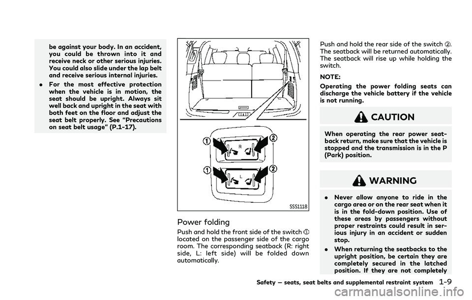
SSS1118
Power folding
Push and hold the front side of the switchlocated on the passenger side of the cargo
room. The corresponding seatback (R: right
side, L: left side) will be folded down
automatically. Push and hold the rear side of the switch
.
The seatback will be returned automatically.
The seatback will rise up while holding the
switch.
NOTE:
Operating the power folding seats can
discharge the vehicle battery if the vehicle
is not running.
CAUTION
When operating the rear power seat-
back return, make sure that the vehicle is
stopped and the transmission is in the P
(Park) position.
WARNING
. Never allow anyone to ride in the
cargo area or on the rear seat when it
is in the fold-down position. Use of
these areas by passengers without
proper restraints could result in ser-
ious injury in an accident or sudden
stop.
. When returning the seatbacks to the
upright position, be certain they are
completely secured in the latched
position. If they are not completely
Safety — seats, seat belts and supplemental restraint system1-9
Page 103 of 516
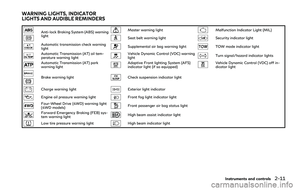
Anti-lock Braking System (ABS) warning
lightMaster warning lightMalfunction Indicator Light (MIL)
Seat belt warning lightSecurity indicator light
Automatic transmission check warning
lightSupplemental air bag warning lightTOW mode indicator light
Automatic Transmission (AT) oil tem-
perature warning lightVehicle Dynamic Control (VDC) warning
lightTurn signal/hazard indicator lights
Automatic Transmission (AT) park
warning lightAdaptive Front lighting System (AFS)
indicator light (if so equipped)Vehicle Dynamic Control (VDC) off in-
dicator light
Brake warning lightCheck suspension indicator light
Charge warning lightExterior light indicator
Engine oil pressure warning lightFront fog light indicator light
Four-Wheel Drive (4WD) warning light
(4WD models)Front passenger air bag status light
Forward Emergency Braking (FEB) sys-
tem warning lightHigh beam assist indicator light
Low tire pressure warning lightHigh beam indicator light
Instruments and controls2-11
WARNING LIGHTS, INDICATOR
LIGHTS AND AUDIBLE REMINDERS
Page 104 of 516
2-12Instruments and controls
CHECKING LIGHTS
With all doors closed, apply the parking
brake, fasten the seat belts and place the
ignition switch in the ON position without
starting the engine. The following lights (if
so equipped) will come on:
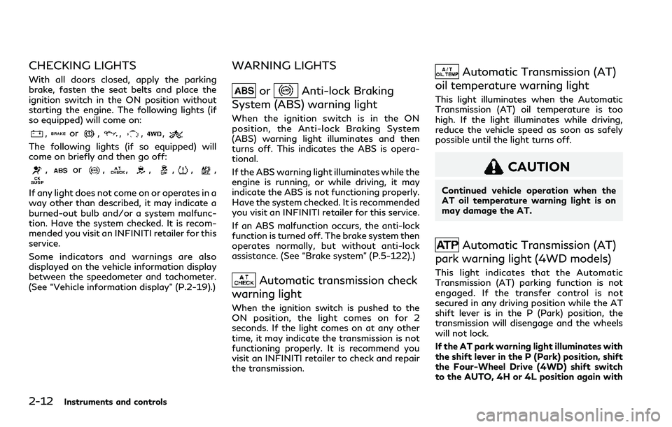
,or,,,,
The following lights (if so equipped) will
come on briefly and then go off:
,or,,,,,,
If any light does not come on or operates in a
way other than described, it may indicate a
burned-out bulb and/or a system malfunc-
tion. Have the system checked. It is recom-
mended you visit an INFINITI retailer for this
service.
Some indicators and warnings are also
displayed on the vehicle information display
between the speedometer and tachometer.
(See “Vehicle information display” (P.2-19).)
WARNING LIGHTS
orAnti-lock Braking
System (ABS) warning light
When the ignition switch is in the ON
position, the Anti-lock Braking System
(ABS) warning light illuminates and then
turns off. This indicates the ABS is opera-
tional.
If the ABS warning light illuminates while the
engine is running, or while driving, it may
indicate the ABS is not functioning properly.
Have the system checked. It is recommended
you visit an INFINITI retailer for this service.
If an ABS malfunction occurs, the anti-lock
function is turned off. The brake system then
operates normally, but without anti-lock
assistance. (See “Brake system” (P.5-122).)
Automatic transmission check
warning light
When the ignition switch is pushed to the
ON position, the light comes on for 2
seconds. If the light comes on at any other
time, it may indicate the transmission is not
functioning properly. It is recommend you
visit an INFINITI retailer to check and repair
the transmission.
Automatic Transmission (AT)
oil temperature warning light
This light illuminates when the Automatic
Transmission (AT) oil temperature is too
high. If the light illuminates while driving,
reduce the vehicle speed as soon as safely
possible until the light turns off.
CAUTION
Continued vehicle operation when the
AT oil temperature warning light is on
may damage the AT.
Automatic Transmission (AT)
park warning light (4WD models)
This light indicates that the Automatic
Transmission (AT) parking function is not
engaged. If the transfer control is not
secured in any driving position while the AT
shift lever is in the P (Park) position, the
transmission will disengage and the wheels
will not lock.
If the AT park warning light illuminates with
the shift lever in the P (Park) position, shift
the Four-Wheel Drive (4WD) shift switch
to the AUTO, 4H or 4L position again with
Page 111 of 516

VDC system is disabled and the VDC off
indicator light illuminates. (4WD models)
For additional information, see “Vehicle
Dynamic Control (VDC) system” (P.5-124).
AUDIBLE REMINDERS
Key reminder chime
A chime will sound if the driver side door is
opened while the ignition switch is pushed to
the ACC position. Make sure the ignition
switch is pushed to the OFF position, and
take the Intelligent Key with you when
leaving the vehicle.
Light reminder chime
A chime will sound when the driver side door
is opened with the light switch in theorposition and the ignition switch in the
ACC, OFF or LOCK position.
Turn the light switch off when you leave the
vehicle.
Parking brake reminder chime
The chime will sound if the vehicle is driven
at more than 4 MPH (7 km/h) with the
parking brake applied. Stop the vehicle and
release the parking brake.
Brake pad wear warning
The disc brake pads have audible wear
warnings. When a brake pad requires repla-
cement, it will make a high pitched scraping
sound when the vehicle is in motion. This
scraping sound will first occur only when the
brake pedal is depressed. After more wear of
the brake pad, the sound will always be
heard even if the brake pedal is not
depressed. Have the brakes checked as soon
as possible if the warning sound is heard.
JVI1272X
The vehicle information displayis located
between the tachometer and the speed-
ometer, and it displays the warnings and
information. The following items are also
displayed if the vehicle is equipped with
them:
. Odometer/twin trip odometer
— “Odometer/twin trip odometer” (P.2- 7)
. Automatic Transmission (AT)
— “Driving the vehicle” (P.5-17).
. Four-Wheel Drive (4WD) system
— “INFINITI all-mode 4WD
®” (P.5-111)
. Cruise control system
Instruments and controls2-19
VEHICLE INFORMATION DISPLAY
Page 119 of 516

.When a wheel slips
The above system cannot be used in some
situations. (VDC operates and a wheel slips.)
38. Currently unavailable (if so
equipped)
This message appears and the Blind Spot
Intervention®(BSI) system, the Lane Depar-
ture Prevention (LDP) system, Intelligent
Cruise Control (ICC) and Distance Control
Assist (DCA) system will be turned off
automatically under the following condi-
tions:
. When the VDC system is turned off.
. When the SNOW mode is selected.
. When the 4WD shift switch is in the 4H
or 4L position. (4WD models).
“Vehicle Dynamic Control (VDC) system”
(P.5-124), “SNOW mode” (P.5-121),
“INFINITI all-mode 4WD
®system” (P.5-
112), “Blind Spot Intervention®(BSI)” (P.5-
40), “Lane Departure Warning (LDW)/Lane
Departure Prevention (LDP)” (P.5-22), “In-
telligent Cruise Control (ICC)” (P.5-62) and
“Distance Control Assist (DCA)” (P.5-82).
39. Automatic Transmission (AT)
position indicator
This indicator shows the transmission shift
position. See “Automatic transmission” (P.5-18) for
further details.
40. Rear Door Alert is activated
When the rear door alert system is enabled,
this message appears when the rear door
alert system is active and can remind the
driver to check the rear seat.
NOTE:
This system is disabled until a driver enables
it using the rear door alert switch.
For more details, see “Rear door alert” (P.2-
52).
41. Check Rear Seat for all articles
When the rear door alert system is enabled,
this message appears when the vehicle
comes to a complete stop, the shift lever is
moved from the D (Drive) or R (Reverse)
position to P (Park) position, and the driver
exits the vehicle. This message alerts the
driver, after a period of time, to check for
items in the rear seat after the audible alert
has been provided.
NOTE:
This rear door alert system is disabled until
a driver enables it using the rear door alert
switch.
For more details, see “Rear door alert” (P.2-
52).
Instruments and controls2-27
Page 143 of 516

SIC4474
TOW mode should be used when pulling a
heavy trailer or hauling a heavy load. Driving
the vehicle in TOW mode with no trailer/
load or light trailer/light load will not cause
any damage. However, fuel economy may be
reduced, and the transmission/engine driv-
ing characteristics may feel unusual.
Push the TOW mode switch to activate
TOW mode. The indicator light in the vehicle
information display illuminates when TOW
mode is selected. Push the TOW mode
switch again to turn TOW mode off.
TOW mode is automatically canceled when
the ignition switch is placed in the OFF
position.
SIC4455
The vehicle should be driven with the Vehicle
Dynamic Control (VDC) system on for most
driving conditions.
If the vehicle is stuck in mud or snow, the
VDC system reduces the engine output to
reduce wheel spin. The engine speed will be
reduced even if the accelerator is depressed
to the floor. If maximum engine power is
needed to free a stuck vehicle, turn the VDC
system off.
To turn off the VDC system, push the VDC
OFF switch. The
indicator will illumi-
nate.
Push the VDC OFF switch again or restart
the engine to turn on the system. (See
“Vehicle Dynamic Control (VDC) system” (P.5-124).)
Instruments and controls2-51
TOW MODE SWITCH
VEHICLE DYNAMIC CONTROL
(VDC) OFF SWITCH
Page 165 of 516

JVI0429X
3. Press the button for 2 seconds up to 3times.
.If the garage door responds, program-ing is completed.
.If the garage door does not respond,continue with Steps 4-6 for a rolling
code device. A second person may
make the following steps easier. Use a
ladder or other device. Do not stand
on your vehicle to perform the next
steps.
4. At the receiver located on the garage door opener motor in the garage, locate
the “Learn” or “Set” button (the name
and color of the button may vary by
manufacturer but it is usually located near where the hanging antenna wire is
attached to the unit). If there is difficulty
locating the button, reference the garage
door opener’s manual.
5. Press and release the “Learn” or “Set” button.
NOTE:
Once the button is pressed, you have
approximately 30 seconds to initiate the
next step.
6. Return to the vehicle and firmly press and hold the programmed HomeLink
®
button for two seconds and release.
Repeat the “press/hold/release” se-
quence up to 3 times to complete the
programming process. HomeLink
®
should now activate your rolling code
equipped device.
7. If you have any questions or are having difficulty programming your HomeLink
®
buttons, refer to the HomeLink®web
site at: www. homelink.com/infiniti or
call 1-800-355-3515.
PROGRAMMING HomeLink®FOR
CANADIAN CUSTOMERS AND
GATE OPENERS
Canadian radio-frequency laws require
transmitter signals to “time-out” (or quit)
after several seconds of transmission –
which may not be long enough for
HomeLink
®to pick up the signal during
programming. Similar to this Canadian law,
some U.S. gate operators are designed to
“time-out” in the same manner.
If you live in Canada or you are having
difficulties programming a gate operator or
garage door opener by using the “Program-
ming HomeLink
®” procedures, replace “Pro-
gramming HomeLink®” Step 2 with the
following:
NOTE:
When programming a garage door opener,
etc., unplug the device during the “cycling”
process to prevent possible damage to the
garage door opener components.
Step 2: Using both hands, simultaneously
press and hold the desired HomeLink
®
button and the hand-held transmitter but-
ton. During programming, your hand-held
transmitter may automatically stop trans-
mitting. Continue to press and hold the
desired HomeLink
®button while you press
and re-press (“cycle”) your hand-held trans-
Instruments and controls2-73
Page 213 of 516
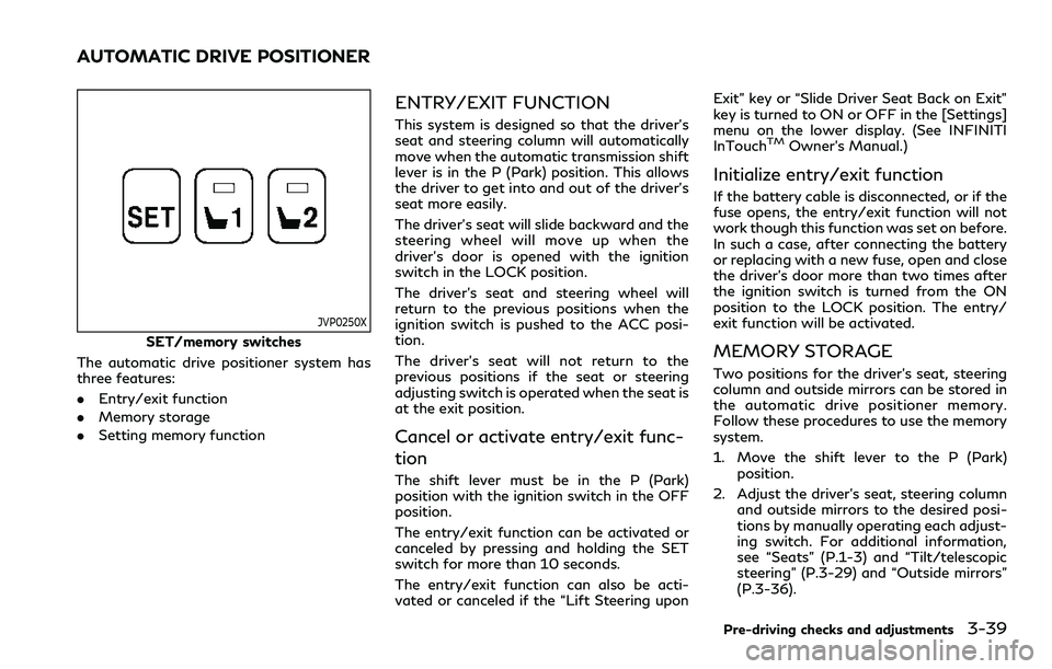
JVP0250X
SET/memory switches
The automatic drive positioner system has
three features:
. Entry/exit function
. Memory storage
. Setting memory function
ENTRY/EXIT FUNCTION
This system is designed so that the driver’s
seat and steering column will automatically
move when the automatic transmission shift
lever is in the P (Park) position. This allows
the driver to get into and out of the driver’s
seat more easily.
The driver’s seat will slide backward and the
steering wheel will move up when the
driver’s door is opened with the ignition
switch in the LOCK position.
The driver’s seat and steering wheel will
return to the previous positions when the
ignition switch is pushed to the ACC posi-
tion.
The driver’s seat will not return to the
previous positions if the seat or steering
adjusting switch is operated when the seat is
at the exit position.
Cancel or activate entry/exit func-
tion
The shift lever must be in the P (Park)
position with the ignition switch in the OFF
position.
The entry/exit function can be activated or
canceled by pressing and holding the SET
switch for more than 10 seconds.
The entry/exit function can also be acti-
vated or canceled if the “Lift Steering upon Exit” key or “Slide Driver Seat Back on Exit”
key is turned to ON or OFF in the [Settings]
menu on the lower display. (See INFINITI
InTouch
TMOwner’s Manual.)
Initialize entry/exit function
If the battery cable is disconnected, or if the
fuse opens, the entry/exit function will not
work though this function was set on before.
In such a case, after connecting the battery
or replacing with a new fuse, open and close
the driver’s door more than two times after
the ignition switch is turned from the ON
position to the LOCK position. The entry/
exit function will be activated.
MEMORY STORAGE
Two positions for the driver’s seat, steering
column and outside mirrors can be stored in
the automatic drive positioner memory.
Follow these procedures to use the memory
system.
1. Move the shift lever to the P (Park)
position.
2. Adjust the driver’s seat, steering column and outside mirrors to the desired posi-
tions by manually operating each adjust-
ing switch. For additional information,
see “Seats” (P.1-3) and “Tilt/telescopic
steering” (P.3-29) and “Outside mirrors”
(P.3-36).
Pre-driving checks and adjustments3-39
AUTOMATIC DRIVE POSITIONER