oil pressure ISUZU AXIOM 2002 Service Owner's Manual
[x] Cancel search | Manufacturer: ISUZU, Model Year: 2002, Model line: AXIOM, Model: ISUZU AXIOM 2002Pages: 2100, PDF Size: 19.35 MB
Page 384 of 2100

4B2±5
DRIVE LINE CONTROL SYSTEM (TOD)
Front and Rear Speed Sensors
The sensors are built in the transfer case, and detect the
rotation of rotors directly coupled to the propeller shafts.
Thirty rectangular pulses are output per one rotation of
the propeller shaft.
261RW045
Electromagnetic Coil
Receives the duty signals from the TOD control unit and
controls the pressing force of the clutch pressure cam.
261RW044
Multi Plate Disk Clutch Pack
Transmits the torque determined by the clutch pressing
force to the front propeller shaft via the front drive chain.
262RW029
Mechanical Lock Sleeve
Couples the front and rear propeller shaft mechanically
when the transfer shaft is in the 4L position.
262RW028
Page 483 of 2100

DRIVE LINE CONTROL SYSTEM (TOD) 4B2±104
StepActionYe sNo
1Are the front and rear tires in specified size?
Go to Step 2
Replace the tires
with specified
ones, and service
the new tires.
Go to
Step 16
2Is the tire pressure correct?
Go to Step 3
Inflate the tires
with specified
pressure.
Go to
Step 16
3Are the tires free from abnormal wear?
Go to Step 4
Replace the tires
with specified
ones, and service
the new tires.
Go to
Step 16
4Are different types of tires used?
Go to Step 5
Replace the tires
with specified
ones, and service
the new tires.
Go to
Step 16
51. Start the engine.
2. Select the TOD switch to the TOD position.
3. Fully turn the steering to the left (or right) end, and select the D
range and start the creep run.
Does the tight corner braking occur? Is the judder with chug-chug
sound observed? * Use caution on the operation.
Go to Step 6 Go to Step 11
61. Select the TOD switch to the 2H position.
2. Fully turn the steering to the left (or right) end, and select the D
range and start the creep run.
Does the tight corner braking occur? Is the judder with chug-chug
sound observed? * Use caution on the operation.
Go to Step 7 Go to Step 14
7Is an LSD mounted to the rear differential? Go to Step 8 Go to Step 9
8Is the genuine LSD oil used in the rear differential?
Go to Step 9
Replace the
differential oil.
Go to
Step 16
9Does the engine output the power correctly?
Go to Step 10
Check the
engine.
Go to
Step 16
10Do the speed sensors work correctly? (Check trouble codes.)The ECU has
failed. Replace
the ECU.
Go to
Step 16
Replace the
speed sensors.
Go to
Step 16
11Is the tight corner braking observed only when the brake is
applied?
Go to Step 12
Conduct full
steering under
WOT.
Go to
Step 5
121. Turn on the starter switch.
Is 8 ~ 10 V observed between terminals 33 and 47?
Go to Step 13
Repair the circuit
of the ECU
connector
terminal 33 (ABS
IN).
Go to
Step 16
Page 622 of 2100

5A±3
BRAKE CONTROL SYSTEM
General Description
The Anti-lock Brake System (ABS) works on all four
wheels. A combination of wheel speed sensor and
Electronic Hydraulic Control Unit (EHCU) can determine
when a wheel is about to stop turning and adjust brake
pressure to maintain best braking.
This system helps the driver maintain greater control of
the vehicle under heavy braking conditions.
NOTE: The Electronic Hydraulic Control Unit (EHCU)
comprises the Hydraulic Unit (H/U) and the coil Integrated
Module.
C05RW004
Legend
(1) Electronic Line
(2) Hydraulic Line
(3) Hydraulic Unit (H/U)(4) Coil Integrated Module
(5) Front Wheel Speed Sensor
(6) Rear Wheel Speed Sensor
(7) Proportioning and Bypass (P&B) Valve
Page 625 of 2100

5A±6BRAKE CONTROL SYSTEM
Pressure Isolation (Pressure Maintain)
The electro-hydraulic control unit is activated when the
brakes are applied.
If the information from the wheel speed sensors indicates
excessive wheel deceleration (imminent lockup), the first
step in the anti-lock sequence is to isolate the brake
pressure being applied by the brake pedal.
The microprocessor in the coil integrated module sends a
voltage to the coil to energize and close the isolation
valve. This prevents any additional fluid pressure applied
by the brake pedal from reaching the wheel. With the
isolation valves closed, unnecessary increase in the
brake pressure is prevented.
C05RW011
Legend
(1) Brake
(2) Master Cylinder
Page 629 of 2100

5A±10BRAKE CONTROL SYSTEM
System Components
Electronic Hydraulic Control Unit (EHCU), three Wheel
Speed Sensors, Warning Light, and G-sensor.
Electronic Hydraulic Control Unit (EHCU)
The EHCU consists of ABS control circuits, fault detector,
and a fail-safe. The signal received from each sensor
activates the hydraulic unit accordingly and cancels the
ABS to return to normal braking if a malfunction occurs in
the ABS system.
The EHCU has a self-diagnosing function which can
indicate faulty circuits during diagnosis.
The EHCU is mounted on the engine compartment rear
right side. It consists of a Motor, Plunger Pump, Solenoid
Valves.
Solenoid Valves: Reduces or holds the caliper fluid
pressure for each front disc brake or both rear disc brakes
according to the signal sent from the EHCU.
Reservoir: Temporarily holds the brake fluid that returns
from the front and rear disc brake caliper so that pressure
of front disc brake caliper can be reduced smoothly.
Plunger Pump: Feeds the brake fluid held in the reservoir
to the master cylinder.
Motor: Drives the pump according to the signal from
EHCU.
Check Valve: Controls the brake fluid flow.
ABS Warning Light
821R200015Vehicles equipped with the Anti-lock Brake System have
an amber ªABSº warning light in the instrument panel.
The ªABSº warning light will illuminate if a malfunction in
the Anti-lock Brake System is detected by the Electronic
Hydraulic Control Unit (EHCU).In case of an electronic
malfunction, the EHCU will turn ªONº the ªABSº warning
light and disable the Anti-lock braking function.
The ªABSº light will turn ªONº for approximately three
seconds after the ignition switch is turned to the ªONº
position.If the ªABSº light stays ªONº after the ignition switch is
turned to the ªONº position, or comes ªONº and stays
ªONº while driving, the Anti-lock Brake System should be
inspected for a malfunction according to the diagnosis
procedure.
Wheel Speed Sensor
It consists of a sensor and a rotor. The sensor is attached
to the knuckle on the front wheels and to the rear axle
case on the rear differential.
The front sensor rotor is attached to the each brake rotor
by bolts.
The rear rotor is press-fit in the differential case.
The magnetic flux generated from electrodes magnetized
by a magnet in the sensor varies due to rotation of the
rotor, and the electromagnetic induction generates
alternating voltage in the coil. This voltage draws a ªsine
curveº with the frequency proportional to rotor speed and
it allows detection of wheel speed.
G-Sensor
The G-sensor installed inside the EHCU detects the
vehicle deceleration speed and sends a signal to the
EHCU. In 4WD operation, all four wheels may be
decelerated in almost the same phase, since all wheels
are connected mechanically.
This tendency is noticeable particularly on roads with low
friction coefficient, and the ABS control is adversely
affected.
The G-sensor judges whether the friction coefficient of
road surface is low or high, and changes the EHCU's
operating system to ensure ABS control.
Normal and Anti-lock Braking
Under normal driving conditions, the Anti-lock Brake
System functions the same as a standard power assisted
brake system. However, with the detection of wheel
lock-up, a slight bump or kick-back will be felt in the brake
pedal. This pedal ªbumpº will be followed by a series of
short pedal pulsations which occurs in rapid succession.
The brake pedal pulsation will continue until there is no
longer a need for the anti-lock function or until the vehicle
is stopped. A slight ticking or popping noise may be heard
during brake applications when the Anti-lock features is
being used.
When the Anti-lock feature is being used, the brake pedal
may rise even as the brakes are being applied. This is
also normal. Maintaining a constant force on the pedal
will provide the shortest stopping distance.
Brake Pedal Travel
Vehicles equipped with the Anti-lock Brake System may
be stopped by applying normal force to the brake pedal.
Although there is no need to push the pedal beyond the
point where it stops or holds the vehicle, by applying more
force the pedal will continue to travel toward the floor.
This extra brake pedal travel is normal.
Page 683 of 2100

5C±3 POWER±ASSISTED BRAKE SYSTEM
The master cylinder contains two pistons that supply the
hydraulic pressure for a dual±circuit braking system. The
primary piston provides the fluid pressure to the front
brakes, while the secondary piston provides the fluid
pressure to the rear brakes. If the pressure is lost from
either system, the remaining system will function to stop
the vehicle.CAUTION:
1. The master cylinder is not repairable. If found
defective, it must be replaced as a complete
assembly.
2. If any hydraulic component is removed or
disconnected, it may be necessary to bleed all or
part of the brake system. (Refer to
Bleeding Brake
Hydraulic System
in this section.)
3. The torque values specified are for dry,
unlubricated fasteners.
4. Perform service operations on a clean bench free
from all mineral oil materials.
Brake Booster
331RS001
This booster is a tandem vacuum unit with a diaphragm
effective diameter 205mm (8.072 in) + 230mm (9.056 in).
In normal operating mode, with the service brakes in the
released position, the tandem vacuum booster operates
with vacuum on both sides of its diaphragms. When the
brakes are applied, air at atmospheric pressure is
admitted to both sides of the diaphragm to provide the
power assist. When the service brake is released, the
atmospheric air is shut off from both sides of the
diaphram. The air is then drawn from the booster through
the vacuum check valve to the vacuum source.CAUTION:
1. If any hydraulic component is removed or
disconnected, it may be necessary to bleed all or
part of the brake system.
2. The torque values specified are for dry,
unlubricated fasteners.
3. The vacuum booster is not repairable and must be
replaced as complete assembly.
Page 684 of 2100

5C±4
POWER±ASSISTED BRAKE SYSTEM
Disc Brake
Front Disc Brake
A05RW001
Rear Disc Brake (4y4 Model)
A05RW002
The disc brake assembly consists of a caliper, piston,
rotor, pad assembly and support bracket. The caliper
assembly has a single bore and is mounted to the support
bracket with two mounting bolts. The support bracket
allows the caliper to move laterally against the rotor. The
caliper is a one±piece casting with the inboard side
containing the piston bore. A square cut rubber seal is
located in a groove in the piston bore which provides the
hydraulic seal between the piston and the cylinder wall.
NOTE:
1. Replace all components included in repair kits used to
service this caliper.
2. Lubricate rubber parts with clean brake fluid to ease
assembly.3. If any hydraulic component is removed or
disconnected, it may be necessary to bleed all or part
of the brake system.
4. Replace pads in axle sets only.
5. The torque values specified are for dry, unlubricated
fasteners.
6. Perform the service operation on a clean bench free
from all mineral oil materials.
Operation
Hydraulic pressure, created by applying the brake pedal,
is converted by the caliper to a stopping force. This force
creates a clamping action of the piston pressing towards
the rotors (outward) and the caliper slides inward toward
the vehicle. This clamping action forces the linings
against the rotor, creating friction to stop the vehicle.
Page 687 of 2100

5C±7 POWER±ASSISTED BRAKE SYSTEM
General Diagnosis
ConditionPossible causeCorrection
Brake PullTire inflation pressure is unequal.Adjust
Front wheel alignment is incorrect.Adjust
Unmatched tires on same axle.Tires with approx. the same amount
of tread should be used on the same
axle.
Restricted brake pipes or hoses.Check for soft hoses and damaged
lines. Replace with new hoses and
new doubleªwalled steel brake
piping.
Water or oil on the brake pads.Clean or replace.
Brake pads hardened.Replace
Brake pads worn excessively.Replace
Brake rotor worn or scored.Grind or replace.
Disc brake caliper malfunctioning.Clean or replace.
Front hub bearing preload incorrect.Adjust or replace.
Loose suspension parts.Check all suspension mountings.
Loose calipers.Check and tighten the bolts to
specifications.
Brake Roughness or Chatter
(Pulsates)Excessive lateral runout.Check per instructions. If not within
specifications, replace or machine
the rotor.
Parallelism not within specifications.Check per instructions. If not within
specifications, replace or machine
the rotor.
Wheel bearings not adjusted.Adjust wheel bearings to correct
specifications
Pad reversed (steel against iron).Replace the brake pad and machine
rotor to within specifications.
Excessive Pedal EffortMalfunctioning vacuum booster.Check the vacuum booster operation
and repair, if necessary.
Partial system failure.Check the front and rear brake
system for failure and repair. Also,
check the brake warning light. If a
failed system is found, the light
should indicate failure.
Excessively worn pad.Check and replace pads in sets.
Piston in caliper stuck or sluggish.Remove caliper and rebuild.
Fading brakes due to incorrect pad.Remove and replace with original
equipment pad or equivalent.
Vacuum leak to vacuum booster.Check for ruptured or loose hose.
Check the direction of check valve
within vacuum hose.Correct vacuum hose direction.
Grease on the brake pads.Replace or clean.
Page 690 of 2100

5C±10
POWER±ASSISTED BRAKE SYSTEM
Hydraulic Brakes
Filling Master Cylinder Reservoir
CAUTION: Use only specified brake fluid. Do not
use any fluid which contains a petroleum base. Do
not use a container which has been used for
petroleum based fluids or a container which is wet
with water. Petroleum based fluid will cause swelling
and distortion of rubber parts in the hydraulic brake
system. Water mixed with brake fluid lowers the fluid
boiling point. Keep all fluid containers capped to
prevent contamination.
Always fill the master cylinder reservoir when the en-
gine is cold.
Never allow the brake fluid to come in contact with
the painted surfaces.
The master cylinder reservoir must be kept properly
filled to ensure adequate reserve and to prevent air
and moisture from entering the hydraulic system.
However, because of expansion due to heat ab-
sorbed from the brakes and the engine, the reservoir
must not be overfilled. The brake fluid reservoir is on
the master cylinder, which is located under the hood
on the left side of the cowl. Thoroughly clean reser-
voir cap before removal to avoid getting dirt into res-
ervoir. Remove the diaphragm. Add fluid as required
to bring level to the ªMAXº mark on the reservoir
tank. Use ªDOT 3º Hydraulic Brake Fluid. If the fluid
cap diaphragm is stretched, return it to the original
position before installing.
Deterioration of Brake Fluid
Using any other brake fluid than specified or brake fluid
with mineral oil or water mixed in will drop the boiling point
of brake fluid. It may, in turn, result in vapor lock or
deteriorated rubber parts of the hydraulic system. Be sure
to change the brake fluid at specified intervals.
If the rubber parts are deteriorated, remove all the system
parts and clean them with alcohol. Prior to reassembly,
dry the cleaned parts with air to remove the alcohol.
Replace all the hoses and rubber parts of the system.
Leakage of Brake Fluid
With engine idling, set shift lever in the neutral position
and continue to depress brake pedal at a constant pedal
application force.
Should the pedal stroke become deeper gradually,
leakage from the hydraulic pressure system is possible.
Perform visual inspection for any signs of leakage.
Bleeding Brake Hydraulic System
A bleeding operation is necessary to remove air from the
hydraulic brake system whenever air is introduced into
the hydraulic system. It may be necessary to bleed the
hydraulic system at all four brakes if air has been
introduced through a low fluid level or by disconnecting
brake pipes at the master cylinder. If a brake pipe is
disconnected at one wheel, only that wheel
cylinder/caliper needs to be bled. If the pipes aredisconnected at any fitting located between the master
cylinder and brakes, then the brake system served by the
disconnected pipe must be bled.
1. For 4±Wheel Antilock Brake System (ABS) equipped
vehicle, be sure to remove the ABS main fuse 60A
located at the relay and fuse box before bleeding air. If
you attempt to bleed air without removing the main
fuse, air cannot be let out thoroughly, and this may
cause damage to the hydraulic unit. After bleeding air,
be sure to replace the ABS main fuse back to its
original position.
2. Set the parking brake completely, then start the
engine.
NOTE: The vacuum booster will be damaged if the
bleeding operation is performed with the engine off.
3. Remove the master cylinder reservoir cap.
4. Fill the master cylinder reservoir with brake fluid.
Keep the reservoir at least half full during the air
bleeding operation
5. Always use new brake fluid for replenishment.
6. When replenishing the brake fluid reservoir, carefully
pour in the brake fluid to prevent air bubbles from
entering the brake system.
When the master cylinder is replaced or overhauled,
first bleed the air from the master cylinder, then from
each wheel cylinder and caliper following the
procedures described below.
Bleeding the Master Cylinder
7. Disconnect the rear wheel brake pipe (1) from the
master cylinder.
Check the fluid level and replenish as necessary. If
replenished, leave the system for at least one minute.
8. Depress the brake pedal slowly once and hold it
depressed.
9. Completely seal the delivery port of the master
cylinder with your finger, where the pipe was
disconnected then release the brake pedal slowly.
10. Release your finger from the delivery port when the
brake pedal returns completely.
11. Repeat steps 8 through 10 until the brake fluid comes
out of the delivery port during step 8.
NOTE: Do not allow the fluid level in the reservoir to go
below the half±way mark.
12. Reconnect the brake pipe (1) to the master cylinder
and tighten the pipe.
13. Depress the brake pedal slowly once and hold it
depressed.
14. Loosen the rear wheel brake pipe (1) at the master
cylinder.
15. Retighten the brake pipe, then release the brake
pedal slowly.
16. Repeat steps 13 through 15 until no air comes out of
the port when the brake pipe is loosened
NOTE: Be very careful not to allow the brake fluid to come
in contact with painted surfaces.
Page 703 of 2100
5C±23 POWER±ASSISTED BRAKE SYSTEM
Functional Inspection of Master Cylinder
Piston
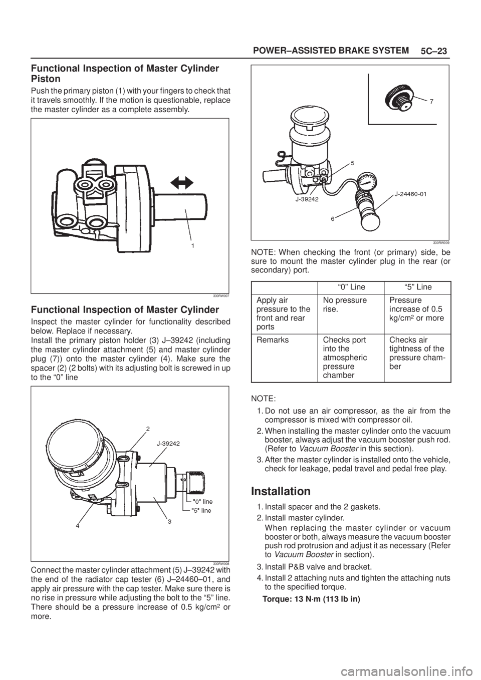
Push the primary piston (1) with your fingers to check that
it travels smoothly. If the motion is questionable, replace
the master cylinder as a complete assembly.
330RW007
Functional Inspection of Master Cylinder
Inspect the master cylinder for functionality described
below. Replace if necessary.
Install the primary piston holder (3) J±39242 (including
the master cylinder attachment (5) and master cylinder
plug (7)) onto the master cylinder (4). Make sure the
spacer (2) (2 bolts) with its adjusting bolt is screwed in up
to the ª0º line
330RW008Connect the master cylinder attachment (5) J±39242 with
the end of the radiator cap tester (6) J±24460±01, and
apply air pressure with the cap tester. Make sure there is
no rise in pressure while adjusting the bolt to the ª5º line.
There should be a pressure increase of 0.5 kg/cm
2 or
more.
330RW009
NOTE: When checking the front (or primary) side, be
sure to mount the master cylinder plug in the rear (or
secondary) port.
ª0º Lineª5º Line
Apply air
pressure to the
front and rear
portsNo pressure
rise.Pressure
increase of 0.5
kg/cm
2 or more
RemarksChecks port
into the
atmospheric
pressure
chamberChecks air
tightness of the
pressure cham-
ber
NOTE:
1. Do not use an air compressor, as the air from the
compressor is mixed with compressor oil.
2. When installing the master cylinder onto the vacuum
booster, always adjust the vacuum booster push rod.
(Refer to
Vacuum Booster in this section).
3. After the master cylinder is installed onto the vehicle,
check for leakage, pedal travel and pedal free play.
Installation
1. Install spacer and the 2 gaskets.
2. Install master cylinder.
When replacing the master cylinder or vacuum
booster or both, always measure the vacuum booster
push rod protrusion and adjust it as necessary (Refer
to
Vacuum Booster in section).
3. Install P&B valve and bracket.
4. Install 2 attaching nuts and tighten the attaching nuts
to the specified torque.
Torque: 13 N´m (113 lb in)