transmission ISUZU AXIOM 2002 Service Owner's Manual
[x] Cancel search | Manufacturer: ISUZU, Model Year: 2002, Model line: AXIOM, Model: ISUZU AXIOM 2002Pages: 2100, PDF Size: 19.35 MB
Page 568 of 2100
4C±71 DRIVE SHAFT SYSTEM
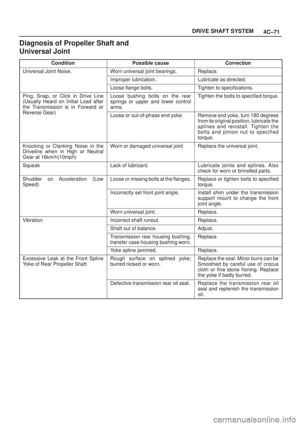
Diagnosis of Propeller Shaft and
Universal Joint
ConditionPossible causeCorrection
Universal Joint Noise.Worn universal joint bearings.Replace.
Improper lubrication.Lubricate as directed.
Loose flange bolts.Tighten to specifications.
Ping, Snap, or Click in Drive Line
(Usually Heard on Initial Load after
the Transmission is in Forward or
Reverse Gear)
Loose bushing bolts on the rear
springs or upper and lower control
arms.Tighten the bolts to specified torque.
Reverse Gear)Loose or out-of-phase end yoke.Remove end yoke, turn 180 degrees
from its original position, lubricate the
splines and reinstall. Tighten the
bolts and pinion nut to specified
torque.
Knocking or Clanking Noise in the
Driveline when in High or Neutral
Gear at 16km/h(10mph)Worn or damaged universal jointReplace the universal joint.
SqueakLack of lubricant.Lubricate joints and splines. Also
check for worn or brinelled parts.
Shudder on Acceleration (Low
Speed)Loose or missing bolts at the flanges.Replace or tighten bolts to specified
torque.
Incorrectly set front joint angle.Install shim under the transmission
support mount to change the front
joint angle.
Worn universal joint.Replace.
VibrationIncorrect shaft runout.Replace.
Shaft out of balance.Adjust.
Transmission rear housing bushing,
transfer case housing bushing worn.Replace.
Yoke spline jammed.Replace.
Excessive Leak at the Front Spline
Yoke of Rear Propeller ShaftRough surface on splined yoke;
burred nicked or worn.Replace the seal. Minor burrs can be
Smoothed by careful use of crocus
cloth or fine stone honing. Replace
the yoke if badly burred.
Defective transmission rear oil seal.Replace the transmission rear oil
seal and replenish the transmission
oil.
Page 575 of 2100

4C±78
DRIVE SHAFT SYSTEM
1. Apply grease evenly to both the female and male
splines.
2. Apply a small amount of grease by finger to the outer
lips of the boot.
3. Slide the boot onto the yoke shaft being careful not to
damage the spline coating or boot.
4. Insert the yoke shaft spline into the sleeve being
careful to maintain proper phasing. The spider holes
should be in line and as per originally marked prior to
disassembly.5. Position boot onto sleeve and yoke shaft in final
position over boot grooves.
6. Attach boot clamps and secure using pliers.
7. Be sure clamp is properly seated and secure.
Main Data and Specifications
General Specifications
TransmissionM/TA/T
Length (between two spiders
center)367.2 mm (14.81 in)542.2 mm (21.35 in)
Torque Specifications
401RX001
Page 576 of 2100

4C±79 DRIVE SHAFT SYSTEM
Rear Propeller Shaft
Rear Propeller Shaft and Associated Parts
401RX003
Legend
(1) Bolt, Nut and Washer (Transfer Side)(2) Rear Propeller Shaft
(3) Bolt, Nut and Washer (Rear Axle Side)
Removal
1. Raise the vehicle on a hoist.
NOTE: Apply alignment marks on the flange at the rear
propeller shaft both front and rear side.
2. Remove transfer side bolt, nut and washer (except
spline yoke type).
3. Remove rear axle side bolt, nut and washer.
4. Remove rear propeller shaft.
NOTE: Plug the hole of the transmission rear end to
prevent oil leakage (spline yoke type only).
Installation
NOTE: Never install the shaft assembly backwards.
Never insert bar between yoke lugs when tightening or re-
moving bolts.
Completely remove the dust or foreign matter from the
connecting surface of flange coupling on each end of the
propeller shaft.
1. Align the mark which is applied at removal.
2. Install rear propeller shaft and tighten the bolts to the
specified torque.
Torque: 63 N´m(46 lb ft)
Page 583 of 2100

4C±86
DRIVE SHAFT SYSTEM
Main Data and Specifications
General Specifications
2WD Model4WD Model
EngineY22SE6VD16VD1
TransmissionM/TA/TM/TA/TM/TA/T
Type (See illustration)121223
Length
between two spiders
center)1314.4mm
(51.75in)1334.7mm
(52.55in)1298.4mm
(51.12in)1323.0mm
(52.09in)1191.2mm
(46.9in)1021.2mm
(40.21in)
Universal joint typeCardan type
Torque Specifications
401R100001
Page 585 of 2100

4D2±2
TRANSFER CASE (TOD)
General Description
A04R200003
The Torque-On-Demand (TOD) is an
electronically-controlled torque-split 4-wheel drive
system with the following features.
Shifting Between High and Low Ranges
The shifting mechanism consists of the cam and shaft rail
assembly, the high/low shift motor and the encoder. The
encoder is built-in to the motor.
The encoder senses high/low range shift motor rotation
position and sends this data to the TOD control unit.
Based on this data, the TOD control unit adjusts motor
rotation speed or stops the motor.
The shifting between the high and low ranges using the
TOD switch only is possible. The vehicle must be stopped
or nearly stopped (vehicle speed less than 2 km/h (1.2
mph) and engine speed less than 1,500 rpm), the
automatic transmission selector level must be in the
neutral (N) position, and the brakes must be applied.
Electronically-controlled Wet-type Multiple
Disc Clutch
The clutch automatically provides the optimum drive
power to the front wheels of the vehicle in response to
varying road surface conditions when the vehicle is
operated in the TOD mode. The delivered power ranges
from 0% to 100% of power train output. Superior
operational stability is maintained over a wide range of
operating conditions.
Front Output Drive
Front output drive is provided by a chain. This reduces the
loud noise associated with 4-wheel drive operation.
Oil Pump Lubrication
An oil pump is used to lubricate the transfer. This ensures
stable multiple-disc clutch operation and maintains the
lubricating oil at a constant temperature.
Page 587 of 2100

4D2±4
TRANSFER CASE (TOD)
Removal
1. Disconnect the battery ground cable.
2. Remove the transfer protector.
3. Disconnect the rear propeller shaft assembly from the
transfer case.
4. Disconnect the front propeller shaft assembly from
the transfer case.
5. Remove the center exhaust pipe.
6. Disconnect the speedometer sensor harness
connector from the speedometer sensor, and remove
the harness clamp from the connector bracket of the
transfer case.
7. Disconnect the engine harness connector from the
transfer harness connector.
8. Support the transfer case with a transmission jack.
9. Remove the transfer bolts.
10. Remove the transfer case assembly.
Installation
1. Apply grease (Besco L2 or its equivalent) to the input
shaft spline.
260RY00011
2. Install the transfer case assembly to the transmission
assembly.
3. Install the transfer bolts to the specified torque (Refer
to
next page).
Torque: 46 N´m (34 lb ft)
4. Connect the engine harness connector to the transfer
harness connector.
5. Install the breather hose up to bottom of the transfer
case breather and clip them firmly.
6. Securely insert the breather hose into the cutout
portion of the transfer case.
260R200001
Page 686 of 2100
5C±6
POWER±ASSISTED BRAKE SYSTEM
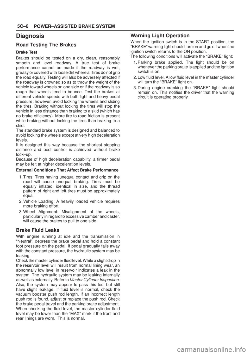
Diagnosis
Road Testing The Brakes
Brake Test
Brakes should be tested on a dry, clean, reasonably
smooth and level roadway. A true test of brake
performance cannot be made if the roadway is wet,
greasy or covered with loose dirt where all tires do not grip
the road equally. Testing will also be adversely affected if
the roadway is crowned so as to throw the weight of the
vehicle toward wheels on one side or if the roadway is so
rough that wheels tend to bounce. Test the brakes at
different vehicle speeds with both light and heavy pedal
pressure; however, avoid locking the wheels and sliding
the tires. Braking without locking the tires will stop the
vehicle in less distance than braking to a skid (which has
no brake efficiency). More tire to road friction is present
while braking without locking the tires than braking to a
skid.
The standard brake system is designed and balanced to
avoid locking the wheels except at very high deceleration
levels.
It is designed this way because the shortest stopping
distance and best control is achieved without brake
lock±up.
Because of high deceleration capability, a firmer pedal
may be felt at higher deceleration levels.
External Conditions That Affect Brake Performance
1. Tires: Tires having unequal contact and grip on the
road will cause unequal braking. Tires must be
equally inflated, identical in size, and the thread
pattern of right and left tires must be approximately
equal.
2. Vehicle Loading: A heavily loaded vehicle requires
more braking effort.
3. Wheel Alignment: Misalignment of the wheels,
particularly in regard to excessive camber and caster,
will cause the brakes to pull to one side.
Brake Fluid Leaks
With engine running at idle and the transmission in
ªNeutralº, depress the brake pedal and hold a constant
foot pressure on the pedal. If pedal gradually falls away
with the constant pressure, the hydraulic system may be
leaking.
Check the master cylinder fluid level. While a slight drop in
the reservoir level will result from normal lining wear, an
abnormally low level in reservoir indicates a leak in the
system. The hydraulic system may be leaking internally
as well as externally. Refer to
Master Cylinder Inspection.
Also, the system may appear to pass this test but still
have slight leakage. If fluid level is normal, check the
vacuum booster push rod length. If an incorrect length
push rod is found, adjust or replace the push rod. Check
the brake pedal travel and the parking brake adjustment.
When checking the fluid level, the master cylinder fluid
level may be lower than the ªMAXº mark if the front and
rear linings are worn. This is normal.
Warning Light Operation
When the ignition switch is in the START position, the
ªBRAKEº warning light should turn on and go off when the
ignition switch returns to the ON position.
The following conditions will activate the ªBRAKEº light:
1. Parking brake applied. The light should be on
whenever the parking brake is applied and the ignition
switch is on.
2. Low fluid level. A low fluid level in the master cylinder
will turn the ªBRAKEº light on.
3. During engine cranking the ªBRAKEº light should
remain on. This notifies the driver that the warning
circuit is operating properly.
Page 746 of 2100
5C±66
POWER±ASSISTED BRAKE SYSTEM
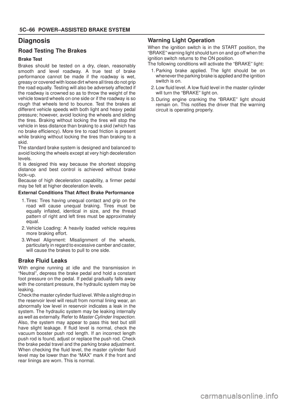
Diagnosis
Road Testing The Brakes
Brake Test
Brakes should be tested on a dry, clean, reasonably
smooth and level roadway. A true test of brake
performance cannot be made if the roadway is wet,
greasy or covered with loose dirt where all tires do not grip
the road equally. Testing will also be adversely affected if
the roadway is crowned so as to throw the weight of the
vehicle toward wheels on one side or if the roadway is so
rough that wheels tend to bounce. Test the brakes at
different vehicle speeds with both light and heavy pedal
pressure; however, avoid locking the wheels and sliding
the tires. Braking without locking the tires will stop the
vehicle in less distance than braking to a skid (which has
no brake efficiency). More tire to road friction is present
while braking without locking the tires than braking to a
skid.
The standard brake system is designed and balanced to
avoid locking the wheels except at very high deceleration
levels.
It is designed this way because the shortest stopping
distance and best control is achieved without brake
lock±up.
Because of high deceleration capability, a firmer pedal
may be felt at higher deceleration levels.
External Conditions That Affect Brake Performance
1. Tires: Tires having unequal contact and grip on the
road will cause unequal braking. Tires must be
equally inflated, identical in size, and the thread
pattern of right and left tires must be approximately
equal.
2. Vehicle Loading: A heavily loaded vehicle requires
more braking effort.
3. Wheel Alignment: Misalignment of the wheels,
particularly in regard to excessive camber and caster,
will cause the brakes to pull to one side.
Brake Fluid Leaks
With engine running at idle and the transmission in
ªNeutralº, depress the brake pedal and hold a constant
foot pressure on the pedal. If pedal gradually falls away
with the constant pressure, the hydraulic system may be
leaking.
Check the master cylinder fluid level. While a slight drop in
the reservoir level will result from normal lining wear, an
abnormally low level in reservoir indicates a leak in the
system. The hydraulic system may be leaking internally
as well as externally. Refer to
Master Cylinder Inspection.
Also, the system may appear to pass this test but still
have slight leakage. If fluid level is normal, check the
vacuum booster push rod length. If an incorrect length
push rod is found, adjust or replace the push rod. Check
the brake pedal travel and the parking brake adjustment.
When checking the fluid level, the master cylinder fluid
level may be lower than the ªMAXº mark if the front and
rear linings are worn. This is normal.
Warning Light Operation
When the ignition switch is in the START position, the
ªBRAKEº warning light should turn on and go off when the
ignition switch returns to the ON position.
The following conditions will activate the ªBRAKEº light:
1. Parking brake applied. The light should be on
whenever the parking brake is applied and the ignition
switch is on.
2. Low fluid level. A low fluid level in the master cylinder
will turn the ªBRAKEº light on.
3. During engine cranking the ªBRAKEº light should
remain on. This notifies the driver that the warning
circuit is operating properly.
Page 823 of 2100
6A±13
ENGINE MECHANICAL (6VE1 3.5L)
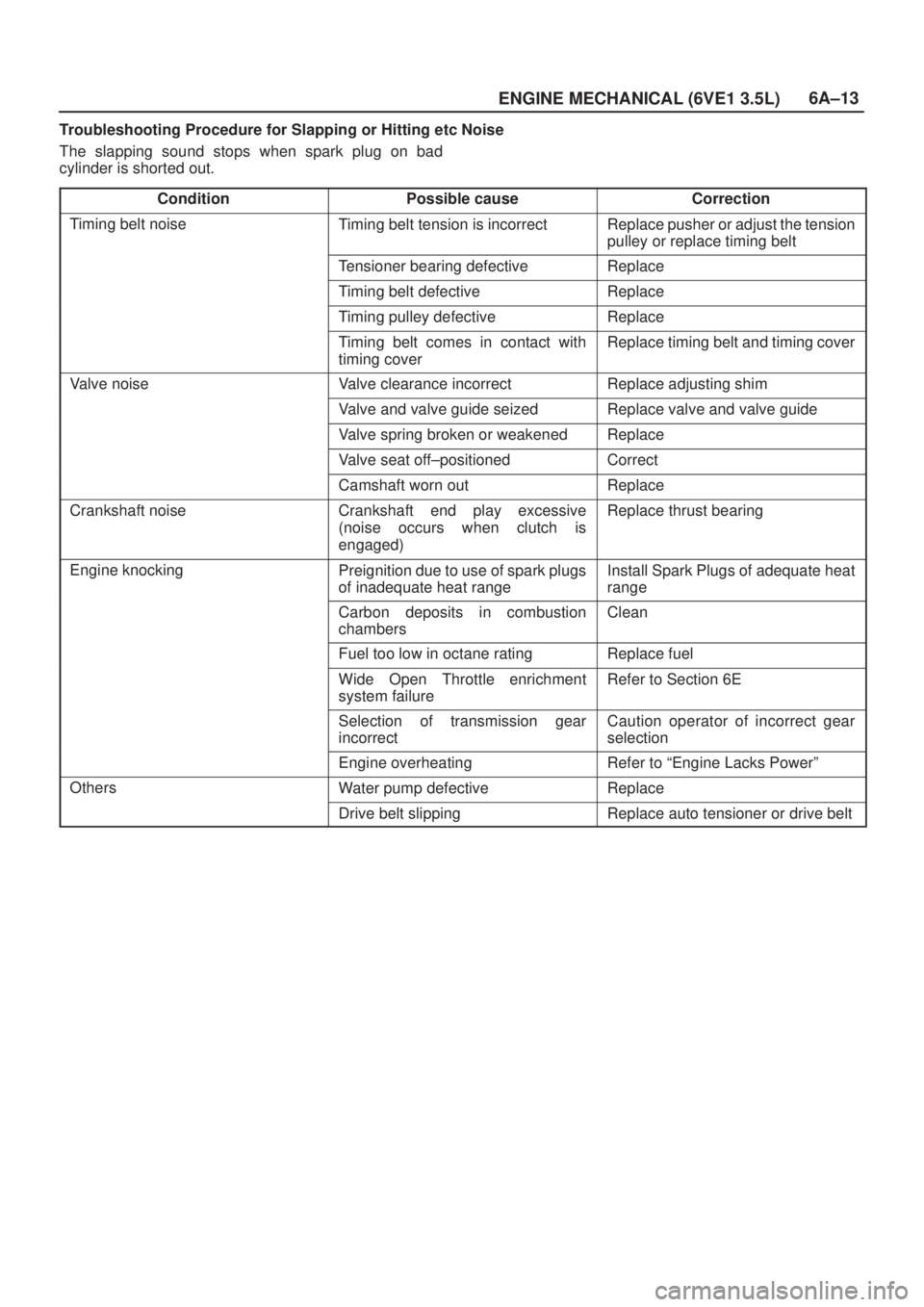
Troubleshooting Procedure for Slapping or Hitting etc Noise
The slapping sound stops when spark plug on bad
cylinder is shorted out.
Condition
Possible causeCorrection
Timing belt noiseTiming belt tension is incorrectReplace pusher or adjust the tension
pulley or replace timing belt
Tensioner bearing defectiveReplace
Timing belt defectiveReplace
Timing pulley defectiveReplace
Timing belt comes in contact with
timing coverReplace timing belt and timing cover
Valve noiseValve clearance incorrectReplace adjusting shim
Valve and valve guide seizedReplace valve and valve guide
Valve spring broken or weakenedReplace
Valve seat off±positionedCorrect
Camshaft worn outReplace
Crankshaft noiseCrankshaft end play excessive
(noise occurs when clutch is
engaged)Replace thrust bearing
Engine knockingPreignition due to use of spark plugs
of inadequate heat rangeInstall Spark Plugs of adequate heat
range
Carbon deposits in combustion
chambersClean
Fuel too low in octane ratingReplace fuel
Wide Open Throttle enrichment
system failureRefer to Section 6E
Selection of transmission gear
incorrectCaution operator of incorrect gear
selection
Engine overheatingRefer to ªEngine Lacks Powerº
OthersWater pump defectiveReplace
Drive belt slippingReplace auto tensioner or drive belt
Page 826 of 2100
6A±16
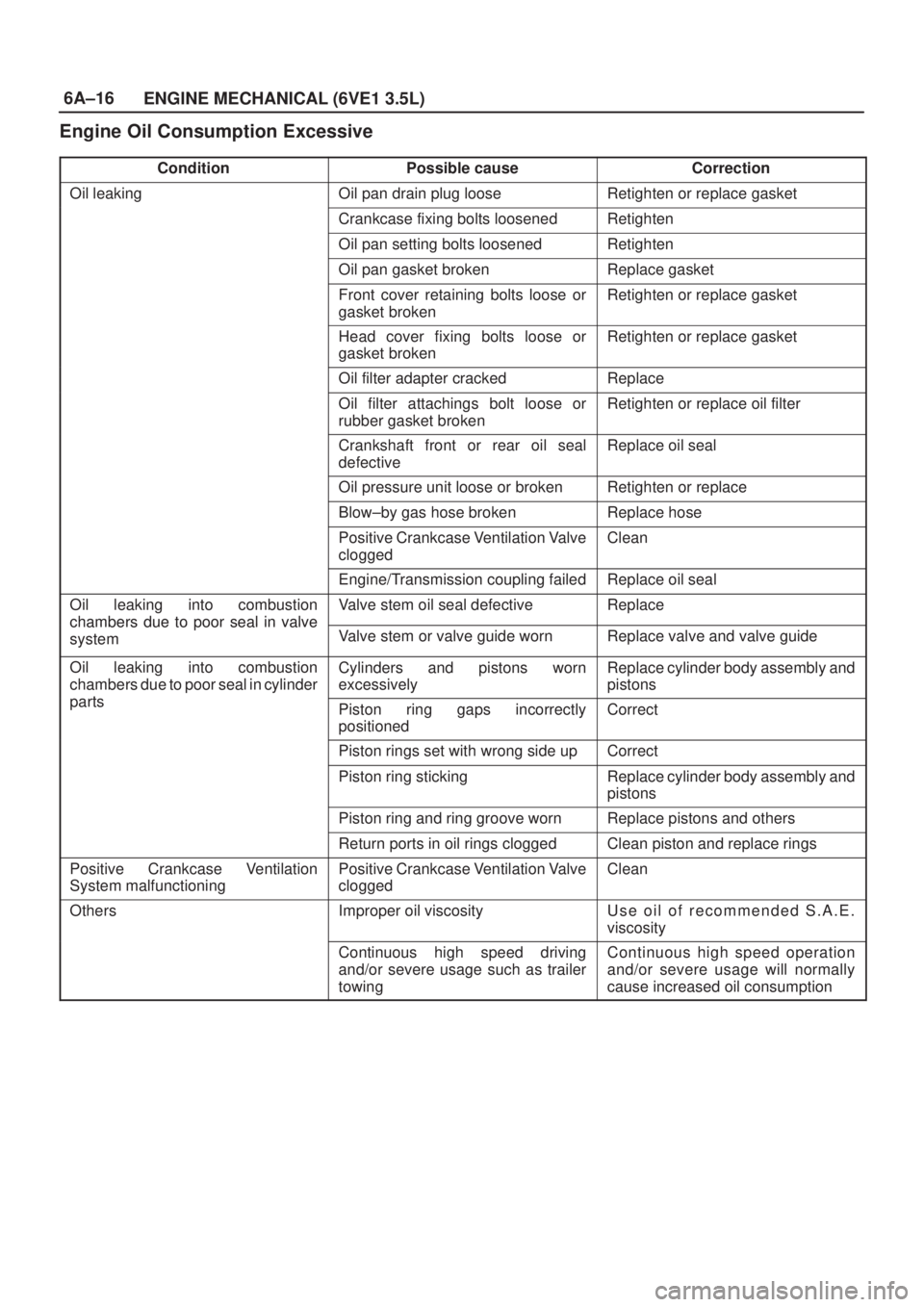
ENGINE MECHANICAL (6VE1 3.5L)
Engine Oil Consumption Excessive
ConditionPossible causeCorrection
Oil leakingOil pan drain plug looseRetighten or replace gasket
Crankcase fixing bolts loosenedRetighten
Oil pan setting bolts loosenedRetighten
Oil pan gasket brokenReplace gasket
Front cover retaining bolts loose or
gasket brokenRetighten or replace gasket
Head cover fixing bolts loose or
gasket brokenRetighten or replace gasket
Oil filter adapter crackedReplace
Oil filter attachings bolt loose or
rubber gasket brokenRetighten or replace oil filter
Crankshaft front or rear oil seal
defectiveReplace oil seal
Oil pressure unit loose or brokenRetighten or replace
Blow±by gas hose brokenReplace hose
Positive Crankcase Ventilation Valve
cloggedClean
Engine/Transmission coupling failedReplace oil seal
Oil leaking into combustion
chambers due topoor seal in valve
Valve stem oil seal defectiveReplace
chambers due to oor seal in valve
systemValve stem or valve guide wornReplace valve and valve guide
Oil leaking into combustion
chambers due to poor seal in cylinder
t
Cylinders and pistons worn
excessivelyReplace cylinder body assembly and
pistons
partsPiston ring gaps incorrectly
positionedCorrect
Piston rings set with wrong side upCorrect
Piston ring stickingReplace cylinder body assembly and
pistons
Piston ring and ring groove wornReplace pistons and others
Return ports in oil rings cloggedClean piston and replace rings
Positive Crankcase Ventilation
System malfunctioningPositive Crankcase Ventilation Valve
cloggedClean
OthersImproper oil viscosityUse oil of recommended S.A.E.
viscosity
Continuous high speed driving
and/or severe usage such as trailer
towingContinuous high speed operation
and/or severe usage will normally
cause increased oil consumption