lighting system ISUZU AXIOM 2002 Service Repair Manual
[x] Cancel search | Manufacturer: ISUZU, Model Year: 2002, Model line: AXIOM, Model: ISUZU AXIOM 2002Pages: 2100, PDF Size: 19.35 MB
Page 1 of 2100
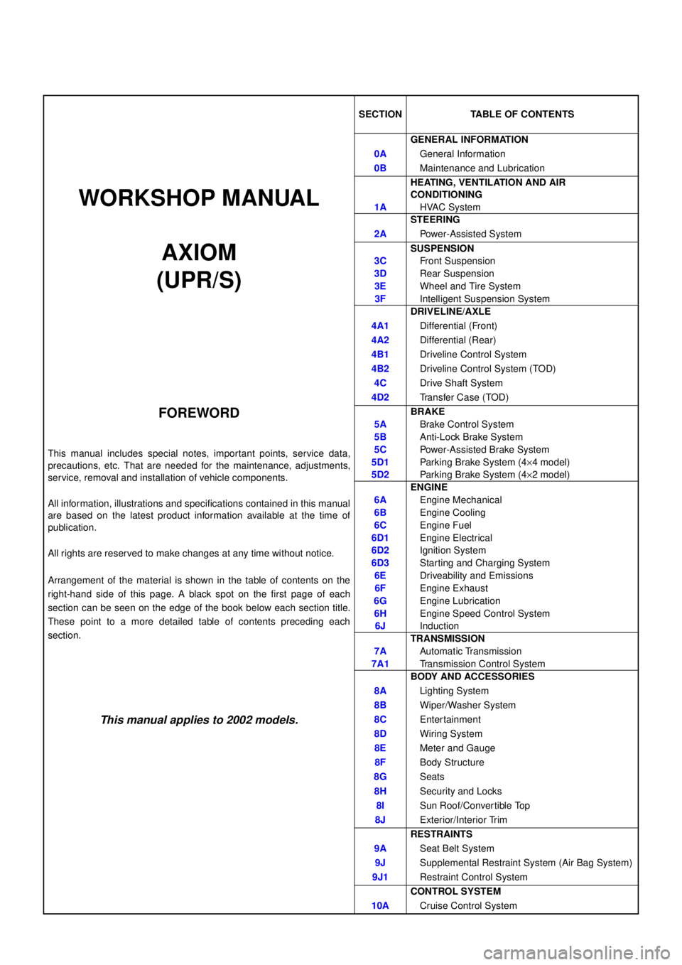
SECTION TABLE OF CONTENTS
GENERAL INFORMATION
0AGeneral Information
0BMaintenance and Lubrication
WORKSHOP MANUAL
HEATING, VENTILATION AND AIR
CONDITIONING
1AHVAC System
STEERING
2APower-Assisted System
AXIOM
(UPR/S)SUSPENSION
3CFront Suspension
3DRear Suspension
3EWheel and Tire System
3FIntelligent Suspension System
DRIVELINE/AXLE
4A1Differential (Front)
4A2Differential (Rear)
4B1Driveline Control System
4B2Driveline Control System (TOD)
4CDrive Shaft System
4D2Transfer Case (TOD)
FOREWORD
This manual includes special notes, impor tant points, service data,
precautions, etc. That are needed for the maintenance, adjustments,
service, removal and installation of vehicle components.
All information, illustrations and specifications contained in this manual
are based on the latest product information available at the time of
publication.
All rights are reserved to make changes at any time without notice.
Arrangement of the material is shown in the table of contents on the
right-hand side of this page. A black spot on the first page of each
section can be seen on the edge of the book below each section title.
These point to a more detailed table of contents preceding each
section.BRAKE
5ABrake Control System
5BAnti-Lock Brake System
5CPower-Assisted Brake System
5D1Parking Brake System (4´4 model)
5D2Parking Brake System (4´2 model)
ENGINE
6AEngine Mechanical
6BEngine Cooling
6CEngine Fuel
6D1Engine Electrical
6D2Ignition System
6D3Starting and Charging System
6EDriveability and Emissions
6FEngine Exhaust
6GEngine Lubrication
6HEngine Speed Control System
6JInduction
TRANSMISSION
7AAutomatic Transmission
7A1Transmission Control System
BODY AND ACCESSORIES
8ALighting System
8BWiper/Washer System
This manual applies to 2002 models.8CEnter tainment
8DWiring System
8EMeter and Gauge
8FBody Structure
8GSeats
8HSecurity and Locks
8ISun Roof/Convertible Top
8JExterior/Interior Trim
RESTRAINTS
9ASeat Belt System
9JSupplemental Restraint System (Air Bag System)
9J1Restraint Control System
CONTROL SYSTEM
10ACruise Control System
Page 114 of 2100

1A±88
HEATING, VENTILATION AND AIR CONDITIONING (HVAC)
Chart ªAº: Check of Auto Amplifier Power Supply System
StepActionValue(s)Ye sNo
1Is the fuse C±5 normal?
ÐGo to Step 2
Replace the
fuse
2Is the fuse F±7 normal?
ÐGo to Step 3
Replace the
fuse
3Disconnect the auto A/C control unit connector I±19.
Is the battery voltage applied between the harness side
connector terminal No.I32±8 and the ground?
Approx. 12VGo to Step 5Go to Step 4
4Repair an open circuit between the fuse C±5 and
terminal No.I19±8.
Is the action complete?
ÐGo to Step 4Ð
5Is there continuity between the harness side connector
terminal No.I19±16 and the ground?
ÐGo to Step 7 Go to Step 6
6Repair an open circuit between terminal No.I19±16 and
the ground No.B±9.
Is the action complete?
ÐGo to Step 5Ð
7Turn the lighting switch on.
Is the battery voltage applied between the harness side
connector terminal No.I19±12 and the ground?
Approx. 12VGo to Step 9Go to Step 8
8Repair an open circuit between the lighting switch and
terminal No.I19±12.
Is the action complete?
ÐGo to Step 7Ð
9Turn the starter switch on.
Is the battery voltage applied between the harness side
connector terminal No.I19±7 and the ground?
Approx. 12VÐGo to Step 10
10Repair an open circuit between the fuse F±7 and
terminal No.I19±7.
Is the action complete?
ÐVerify repairÐ
Page 393 of 2100
DRIVE LINE CONTROL SYSTEM (TOD) 4B2±14
Diagnosis
General Information Diagnosis
The troubles on TOD are classified into the group that can
be identified by the lighting status of the TOD indicator
lamps and those that can be recognized as abnormal
phenomena of the vehicle by the driver.
The troubles that can be identified by the lighting status of
the TOD indicator lamps are examined by the procedures
ªDiagnosis from Trouble Codesº and ªTrouble Diagnosis
Depending on The Status of TOD Indicatorº. The troubles
that can be recognized as abnormal phenomena of the
vehicle by the driver are examined by the procedure
ªDiagnosis from symptomº.
Self-diagnosis
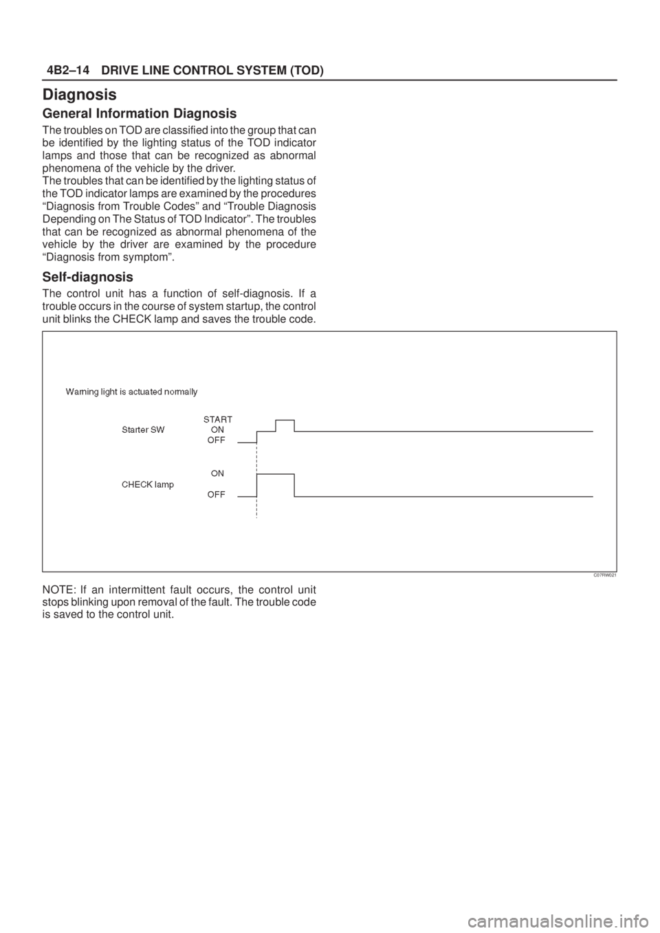
The control unit has a function of self-diagnosis. If a
trouble occurs in the course of system startup, the control
unit blinks the CHECK lamp and saves the trouble code.
C07RW021
NOTE: If an intermittent fault occurs, the control unit
stops blinking upon removal of the fault. The trouble code
is saved to the control unit.
Page 395 of 2100
DRIVE LINE CONTROL SYSTEM (TOD) 4B2±16
How to Clear The Trouble Code
The trouble codes saved to the control unit can be deleted
by the following procedure if the starter switch is being in
the OFF position.
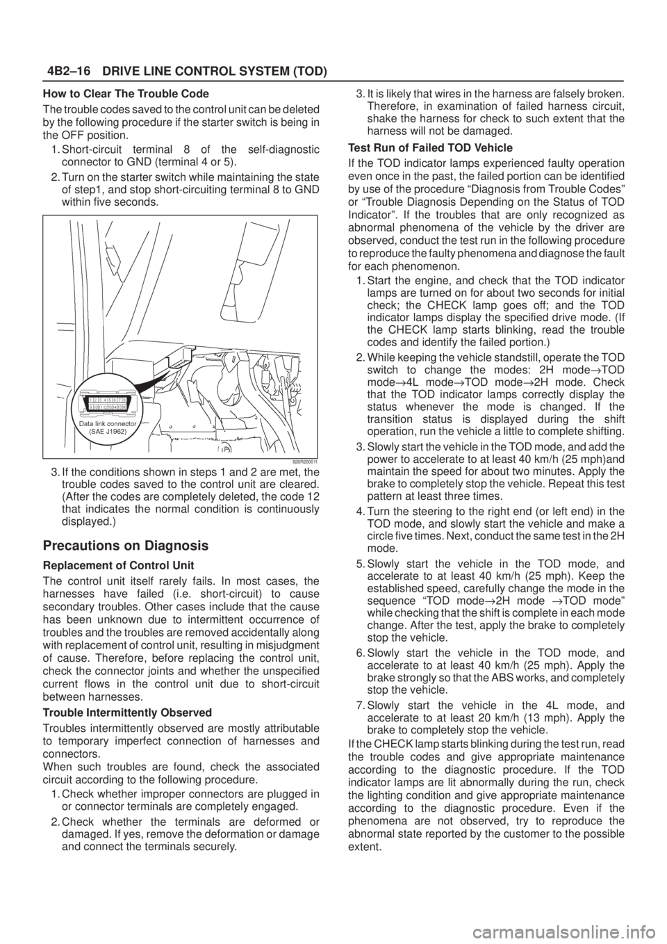
1. Short-circuit terminal 8 of the self-diagnostic
connector to GND (terminal 4 or 5).
2. Turn on the starter switch while maintaining the state
of step1, and stop short-circuiting terminal 8 to GND
within five seconds.
826R200011
3. If the conditions shown in steps 1 and 2 are met, the
trouble codes saved to the control unit are cleared.
(After the codes are completely deleted, the code 12
that indicates the normal condition is continuously
displayed.)
Precautions on Diagnosis
Replacement of Control Unit
The control unit itself rarely fails. In most cases, the
harnesses have failed (i.e. short-circuit) to cause
secondary troubles. Other cases include that the cause
has been unknown due to intermittent occurrence of
troubles and the troubles are removed accidentally along
with replacement of control unit, resulting in misjudgment
of cause. Therefore, before replacing the control unit,
check the connector joints and whether the unspecified
current flows in the control unit due to short-circuit
between harnesses.
Trouble Intermittently Observed
Troubles intermittently observed are mostly attributable
to temporary imperfect connection of harnesses and
connectors.
When such troubles are found, check the associated
circuit according to the following procedure.
1. Check whether improper connectors are plugged in
or connector terminals are completely engaged.
2. Check whether the terminals are deformed or
damaged. If yes, remove the deformation or damage
and connect the terminals securely.3. It is likely that wires in the harness are falsely broken.
Therefore, in examination of failed harness circuit,
shake the harness for check to such extent that the
harness will not be damaged.
Test Run of Failed TOD Vehicle
If the TOD indicator lamps experienced faulty operation
even once in the past, the failed portion can be identified
by use of the procedure ªDiagnosis from Trouble Codesº
or ªTrouble Diagnosis Depending on the Status of TOD
Indicatorº. If the troubles that are only recognized as
abnormal phenomena of the vehicle by the driver are
observed, conduct the test run in the following procedure
to reproduce the faulty phenomena and diagnose the fault
for each phenomenon.
1. Start the engine, and check that the TOD indicator
lamps are turned on for about two seconds for initial
check; the CHECK lamp goes off; and the TOD
indicator lamps display the specified drive mode. (If
the CHECK lamp starts blinking, read the trouble
codes and identify the failed portion.)
2. While keeping the vehicle standstill, operate the TOD
switch to change the modes: 2H mode"TOD
mode"4L mode"TOD mode"2H mode. Check
that the TOD indicator lamps correctly display the
status whenever the mode is changed. If the
transition status is displayed during the shift
operation, run the vehicle a little to complete shifting.
3. Slowly start the vehicle in the TOD mode, and add the
power to accelerate to at least 40 km/h (25 mph)and
maintain the speed for about two minutes. Apply the
brake to completely stop the vehicle. Repeat this test
pattern at least three times.
4. Turn the steering to the right end (or left end) in the
TOD mode, and slowly start the vehicle and make a
circle five times. Next, conduct the same test in the 2H
mode.
5. Slowly start the vehicle in the TOD mode, and
accelerate to at least 40 km/h (25 mph). Keep the
established speed, carefully change the mode in the
sequence ªTOD mode"2H mode "TOD modeº
while checking that the shift is complete in each mode
change. After the test, apply the brake to completely
stop the vehicle.
6. Slowly start the vehicle in the TOD mode, and
accelerate to at least 40 km/h (25 mph). Apply the
brake strongly so that the ABS works, and completely
stop the vehicle.
7. Slowly start the vehicle in the 4L mode, and
accelerate to at least 20 km/h (13 mph). Apply the
brake to completely stop the vehicle.
If the CHECK lamp starts blinking during the test run, read
the trouble codes and give appropriate maintenance
according to the diagnostic procedure. If the TOD
indicator lamps are lit abnormally during the run, check
the lighting condition and give appropriate maintenance
according to the diagnostic procedure. Even if the
phenomena are not observed, try to reproduce the
abnormal state reported by the customer to the possible
extent.
Page 406 of 2100
4B2±27
DRIVE LINE CONTROL SYSTEM (TOD)
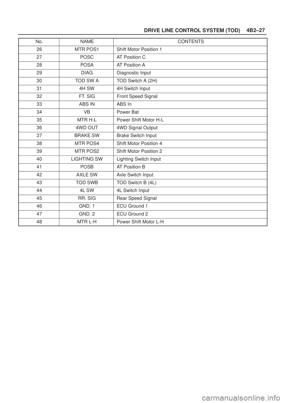
No. CONTENTSNAME
26MTR POS1Shift Motor Position 1
27POSCAT Position C
28POSAAT Position A
29DIAGDiagnostic Input
30TOD SW ATOD Switch A (2H)
314H SW4H Switch Input
32FT. SIGFront Speed Signal
33ABS INABS In
34VBPower Bat
35MTR H-LPower Shift Motor H-L
364WD OUT4WD Signal Output
37BRAKE SWBrake Switch Input
38MTR POS4Shift Motor Position 4
39MTR POS2Shift Motor Position 2
40LIGHTING SWLighting Switch Input
41POSBAT Position B
42AXLE SWAxle Switch Input
43TOD SWBTOD Switch B (4L)
444L SW4L Switch Input
45RR. SIGRear Speed Signal
46GND. 1ECU Ground 1
47GND. 2ECU Ground 2
48MTR L-HPower Shift Motor L-H
Page 479 of 2100

DRIVE LINE CONTROL SYSTEM (TOD) 4B2±100
Chart HLighting switch circuit
Function of circuitReads in the status of lighting switch, and reduces the indicator at night.
Fail conditionEven if the lighting switch is pressed on and off, brightness does not change.
Indicator lamp state
TOD switch positionAll position (exsample TOD mode)
D04R200009
Page 480 of 2100

4B2±101
DRIVE LINE CONTROL SYSTEM (TOD)
StepActionYe sNo
11. Turn on the starter switch.
2. Turn off the lighting switch.
Is 0V observed between the EUC terminal 40 and 47?
Go to Step 2
Lighting switch
battery circuit
short. Repair the
circuit.
Go to
Step 4
2Turn lighting switch ªONº.
Is the battery voltage observed between ECU terminal 40 and 47?
Go to Step 3
Wires are broken
in lighting switch
circuit. Repair the
circuit.
Go to
Step 4
3While the lighting switch is pressed on and off, does the
brightness of the indicator change?The phenomenon
is not
reproduced.
Refer to
ªTroubles
intermittently
observedº
The ECU has
failed. Replace
the ECU.
Go to
Step 4
4Check that all the parts are mounted.
Is this step complete?
Verify the repair.Go to Step 4
Page 655 of 2100

5A±36BRAKE CONTROL SYSTEM
Diagnosis By ªABSº Warning Light
Illumination Pattern
In the event that there is abnormality in the ªABSº warning
light illumination pattern while the key is in the ON position
or if the warning light is actuated while driving, refer to the
flow chart below for the correct diagnostic procedure.
No.
ConditionªABSº Warning Light Illumination PatternDiagnostic
1Warning light is
actuated normallyNormal
2Warning light is not litWarning light lighting circuit
trouble"Go to Chart B-1
3Warning light remains
ONDiagnostic trouble codes are
stored.
Display diagnostic trouble
codes and diagnose on a
code basis according to the
flow charts.
4Warning light is
actuated while drivingDiagnostic trouble codes are
stored.
Display diagnostic trouble
codes and diagnose on a
code basis according to the
flow charts.
5Warning light goes at
12 km/h (8 mph) or
higher (After repairing
the faulty part)Even after repairing the
faulty part the warning light
(W/L) dose not go out if
vehicle is at a stop.
Turn the ignition switch to the
ON position and drive the
vehicle at 12 km/h (8 mph) or
higher to make sure that the
warning light goes out.
Page 1777 of 2100
LIGHTING SYSTEM8A±1
AXIOM
BODY AND ACCESSORIES
CONTENTS
Lighting System 8A. . . . . . . . . . . . . . . . . . . . . . . . .
Wiper / Washer System 8B. . . . . . . . . . . . . . . . . .
Entertainment 8C. . . . . . . . . . . . . . . . . . . . . . . . . . .
Wiring System 8D. . . . . . . . . . . . . . . . . . . . . . . . . .
Meter and Gauge 8E. . . . . . . . . . . . . . . . . . . . . . . Body Structure 8F. . . . . . . . . . . . . . . . . . . . . . . . . .
Seats 8G. . . . . . . . . . . . . . . . . . . . . . . . . . . . . . . . . .
Security and Locks 8H. . . . . . . . . . . . . . . . . . . . . .
Sunroof / Convertible Top 8I. . . . . . . . . . . . . . . .
Exterior / Interior Trim 8J. . . . . . . . . . . . . . . . . . . .
LIGHTING SYSTEM
CONTENTS
Service Precaution 8A±2. . . . . . . . . . . . . . . . . . . . . .
Headlight Bulb 8A±3. . . . . . . . . . . . . . . . . . . . . . . . . .
Removal 8A±3. . . . . . . . . . . . . . . . . . . . . . . . . . . . .
Installation 8A±3. . . . . . . . . . . . . . . . . . . . . . . . . . . .
Headlight Assembly 8A±4. . . . . . . . . . . . . . . . . . . . .
Removal 8A±4. . . . . . . . . . . . . . . . . . . . . . . . . . . . .
Installation 8A±4. . . . . . . . . . . . . . . . . . . . . . . . . . . .
Headlight Adjustment 8A±4. . . . . . . . . . . . . . . . . .
Side Marker Light Bulb 8A±6. . . . . . . . . . . . . . . . . . .
Removal 8A±6. . . . . . . . . . . . . . . . . . . . . . . . . . . . .
Installation 8A±6. . . . . . . . . . . . . . . . . . . . . . . . . . . .
Taillight Bulb 8A±7. . . . . . . . . . . . . . . . . . . . . . . . . . . .
Removal 8A±7. . . . . . . . . . . . . . . . . . . . . . . . . . . . .
Installation 8A±7. . . . . . . . . . . . . . . . . . . . . . . . . . . .
License Plate Light Bulb 8A±8. . . . . . . . . . . . . . . . . .
Removal 8A±8. . . . . . . . . . . . . . . . . . . . . . . . . . . . .
Installation 8A±8. . . . . . . . . . . . . . . . . . . . . . . . . . . .
Stoplight Bulb 8A±8. . . . . . . . . . . . . . . . . . . . . . . . . . .
Removal and Installation 8A±8. . . . . . . . . . . . . . .
High Mounted Stoplight Assembly 8A±9. . . . . . . . .
Removal 8A±9. . . . . . . . . . . . . . . . . . . . . . . . . . . . .
Installation 8A±9. . . . . . . . . . . . . . . . . . . . . . . . . . . .
High Mounted Stoplight Bulb 8A±9. . . . . . . . . . . . . .
Removal 8A±9. . . . . . . . . . . . . . . . . . . . . . . . . . . . .
Installation 8A±9. . . . . . . . . . . . . . . . . . . . . . . . . . . .
Backup Light Bulb 8A±10. . . . . . . . . . . . . . . . . . . . . . .
Removal 8A±10. . . . . . . . . . . . . . . . . . . . . . . . . . . . .
Installation 8A±10. . . . . . . . . . . . . . . . . . . . . . . . . . . .
Front Turn Signal Light Bulb 8A±10. . . . . . . . . . . . . .
Removal and Installation 8A±10. . . . . . . . . . . . . . .
Rear Turn Signal Light Bulb 8A±11. . . . . . . . . . . . . .
Removal 8A±11. . . . . . . . . . . . . . . . . . . . . . . . . . . . .
Installation 8A±11. . . . . . . . . . . . . . . . . . . . . . . . . . . .
Dome Light Bulb 8A±11. . . . . . . . . . . . . . . . . . . . . . . .
Removal 8A±11. . . . . . . . . . . . . . . . . . . . . . . . . . . . .
Installation 8A±11. . . . . . . . . . . . . . . . . . . . . . . . . . . . Map Light Bulb 8A±12. . . . . . . . . . . . . . . . . . . . . . . . . .
Removal 8A±12. . . . . . . . . . . . . . . . . . . . . . . . . . . . .
Installation 8A±12. . . . . . . . . . . . . . . . . . . . . . . . . . . .
Courtesy Light Bulb 8A±12. . . . . . . . . . . . . . . . . . . . . .
Removal 8A±12. . . . . . . . . . . . . . . . . . . . . . . . . . . . .
Installation 8A±12. . . . . . . . . . . . . . . . . . . . . . . . . . . .
Luggage Room Light Bulb 8A±13. . . . . . . . . . . . . . . .
Removal 8A±13. . . . . . . . . . . . . . . . . . . . . . . . . . . . .
Installation 8A±13. . . . . . . . . . . . . . . . . . . . . . . . . . . .
Shift Lever Illumination Light Bulb (A/T) 8A±13. . . .
Removal 8A±13. . . . . . . . . . . . . . . . . . . . . . . . . . . . .
Installation 8A±13. . . . . . . . . . . . . . . . . . . . . . . . . . . .
Vanity Mirror Illumination Light Bulb 8A±14. . . . . . . .
Removal 8A±14. . . . . . . . . . . . . . . . . . . . . . . . . . . . .
Installation 8A±14. . . . . . . . . . . . . . . . . . . . . . . . . . . .
Switch Unit Assembly Illumination
Light Bulb (Power/Winter & Intelligent
Suspension Switch) 8A±14. . . . . . . . . . . . . . . . . . . . .
Removal 8A±14. . . . . . . . . . . . . . . . . . . . . . . . . . . . .
Installation 8A±14. . . . . . . . . . . . . . . . . . . . . . . . . . . .
TOD Switch Illumination Light Bulb 8A±15. . . . . . . .
Removal 8A±15. . . . . . . . . . . . . . . . . . . . . . . . . . . . .
Installation 8A±15. . . . . . . . . . . . . . . . . . . . . . . . . . . .
Cruise Control Main Switch Illumination
Light Bulb 8A±15. . . . . . . . . . . . . . . . . . . . . . . . . . . . . .
Removal 8A±15. . . . . . . . . . . . . . . . . . . . . . . . . . . . .
Installation 8A±15. . . . . . . . . . . . . . . . . . . . . . . . . . . .
Rear Wiper and Washer Switch Illumination
Light Bulb 8A±16. . . . . . . . . . . . . . . . . . . . . . . . . . . . . .
Removal 8A±16. . . . . . . . . . . . . . . . . . . . . . . . . . . . .
Installation 8A±16. . . . . . . . . . . . . . . . . . . . . . . . . . . .
Seat Heater Switch Illumination Light Bulb 8A±16. .
Removal 8A±16. . . . . . . . . . . . . . . . . . . . . . . . . . . . .
Installation 8A±16. . . . . . . . . . . . . . . . . . . . . . . . . . . .
Starter Switch 8A±17. . . . . . . . . . . . . . . . . . . . . . . . . . .
Removal and Installation 8A±17. . . . . . . . . . . . . . .
Lighting Switch (Combination Switch) 8A±17. . . . . .
Page 1778 of 2100

8A±2LIGHTING SYSTEM
Removal and Installation 8A±17. . . . . . . . . . . . . . .
Dimmer´Passing Switch
(Combination Switch) 8A±17. . . . . . . . . . . . . . . . . . .
Removal and Installation 8A±17. . . . . . . . . . . . . . .
Front Door Switch 8A±17. . . . . . . . . . . . . . . . . . . . . . .
Removal 8A±17. . . . . . . . . . . . . . . . . . . . . . . . . . . . .
Installation 8A±17. . . . . . . . . . . . . . . . . . . . . . . . . . . .
Rear Door Switch 8A±18. . . . . . . . . . . . . . . . . . . . . . .
Removal 8A±18. . . . . . . . . . . . . . . . . . . . . . . . . . . . .
Installation 8A±18. . . . . . . . . . . . . . . . . . . . . . . . . . . .
Tailgate Lock Switch 8A±18. . . . . . . . . . . . . . . . . . . . .
Removal 8A±18. . . . . . . . . . . . . . . . . . . . . . . . . . . . .
Installation 8A±18. . . . . . . . . . . . . . . . . . . . . . . . . . . .
Key Remind Switch (Starter Switch) 8A±19. . . . . . . Removal and Installation 8A±19. . . . . . . . . . . . . . .
Hazard Warning Light Switch 8A±19. . . . . . . . . . . . .
Removal 8A±19. . . . . . . . . . . . . . . . . . . . . . . . . . . . .
Installation 8A±19. . . . . . . . . . . . . . . . . . . . . . . . . . . .
Stoplight Switch 8A±20. . . . . . . . . . . . . . . . . . . . . . . . .
Removal and Installation 8A±20. . . . . . . . . . . . . . .
Turn Signal Light Switch
(Combination Switch) 8A±20. . . . . . . . . . . . . . . . . . .
Removal and Installation 8A±20. . . . . . . . . . . . . . .
Illumination Controller 8A±20. . . . . . . . . . . . . . . . . . . .
Removal 8A±20. . . . . . . . . . . . . . . . . . . . . . . . . . . . .
Installation 8A±20. . . . . . . . . . . . . . . . . . . . . . . . . . . .
Main Data and Specifications 8A±21. . . . . . . . . . . . .
Service Precaution
WARNING: THIS VEHICLE HAS A SUPPLEMENTAL
RESTRAINT SYSTEM (SRS). REFER TO THE SRS
COMPONENT AND WIRING LOCATION VIEW IN
ORDER TO DETERMINE WHETHER YOU ARE
PERFORMING SERVICE ON OR NEAR THE SRS
COMPONENTS OR THE SRS WIRING. WHEN YOU
ARE PERFORMING SERVICE ON OR NEAR THE SRS
COMPONENTS OR THE SRS WIRING, REFER TO
THE SRS SERVICE INFORMATION. FAILURE TO
FOLLOW WARNINGS COULD RESULT IN POSSIBLE
AIR BAG DEPLOYMENT, PERSONAL INJURY, OR
OTHERWISE UNNEEDED SRS SYSTEM REPAIRS.CAUTION: Always use the correct fastener in the
proper location. When you replace a fastener, use
ONLY the exact part number for that application.
ISUZU will call out those fasteners that require a
replacement after removal. ISUZU will also call out
the fasteners that require thread lockers or thread
sealant. UNLESS OTHERWISE SPECIFIED, do not
use supplemental coatings (Paints, greases, or other
corrosion inhibitors) on threaded fasteners or
fasteners joint interfaces. Generally, such coatings
adversely affect the fastener torque and the joint
clamping force, and may damage the fasteners.
When you install fasteners, use the correct
tightening sequence and specifications. Following
these instructions can help you avoid damage to
parts and systems.