wiring ISUZU AXIOM 2002 Service Repair Manual
[x] Cancel search | Manufacturer: ISUZU, Model Year: 2002, Model line: AXIOM, Model: ISUZU AXIOM 2002Pages: 2100, PDF Size: 19.35 MB
Page 1 of 2100

SECTION TABLE OF CONTENTS
GENERAL INFORMATION
0AGeneral Information
0BMaintenance and Lubrication
WORKSHOP MANUAL
HEATING, VENTILATION AND AIR
CONDITIONING
1AHVAC System
STEERING
2APower-Assisted System
AXIOM
(UPR/S)SUSPENSION
3CFront Suspension
3DRear Suspension
3EWheel and Tire System
3FIntelligent Suspension System
DRIVELINE/AXLE
4A1Differential (Front)
4A2Differential (Rear)
4B1Driveline Control System
4B2Driveline Control System (TOD)
4CDrive Shaft System
4D2Transfer Case (TOD)
FOREWORD
This manual includes special notes, impor tant points, service data,
precautions, etc. That are needed for the maintenance, adjustments,
service, removal and installation of vehicle components.
All information, illustrations and specifications contained in this manual
are based on the latest product information available at the time of
publication.
All rights are reserved to make changes at any time without notice.
Arrangement of the material is shown in the table of contents on the
right-hand side of this page. A black spot on the first page of each
section can be seen on the edge of the book below each section title.
These point to a more detailed table of contents preceding each
section.BRAKE
5ABrake Control System
5BAnti-Lock Brake System
5CPower-Assisted Brake System
5D1Parking Brake System (4´4 model)
5D2Parking Brake System (4´2 model)
ENGINE
6AEngine Mechanical
6BEngine Cooling
6CEngine Fuel
6D1Engine Electrical
6D2Ignition System
6D3Starting and Charging System
6EDriveability and Emissions
6FEngine Exhaust
6GEngine Lubrication
6HEngine Speed Control System
6JInduction
TRANSMISSION
7AAutomatic Transmission
7A1Transmission Control System
BODY AND ACCESSORIES
8ALighting System
8BWiper/Washer System
This manual applies to 2002 models.8CEnter tainment
8DWiring System
8EMeter and Gauge
8FBody Structure
8GSeats
8HSecurity and Locks
8ISun Roof/Convertible Top
8JExterior/Interior Trim
RESTRAINTS
9ASeat Belt System
9JSupplemental Restraint System (Air Bag System)
9J1Restraint Control System
CONTROL SYSTEM
10ACruise Control System
Page 2 of 2100
0A±1
GENERAL INFORMATION
AXIOM
GENERAL INFORMATION
CONTENTS
General Information 0A. . . . . . . . . . . . . . . . . . . . .
Maintenance and Lubrication 0B. . . . . . . . . . . . .
General Information
CONTENTS
General Repair Instruction 0A±1. . . . . . . . . . . . . . . .
Illustration Arrows 0A±2. . . . . . . . . . . . . . . . . . . . . . .
Identification 0A±3. . . . . . . . . . . . . . . . . . . . . . . . . . . .
Theft Prevention Standard 0A±5. . . . . . . . . . . . . . . . Lifting Instructions 0A±9. . . . . . . . . . . . . . . . . . . . . . .
Standard Bolts Torque Specifications 0A±11. . . . . .
Abbreviations Charts 0A±12. . . . . . . . . . . . . . . . . . . .
Service Parts Identification Plate 0A±13. . . . . . . . . .
General Repair Instruction
1. If a floor jack is used, the following precautions are
recommended.
Park vehicle on level ground, ªblockº front or rear
wheels, set jack against the recommended lifting
points (see ªLifting Instructionsº in this section), raise
vehicle and support with chassis stands and then
perform the service operations.
2. Before performing service operations, disconnect
ground cable from the battery to reduce the chance of
cable damage and burning due to short circuiting.
3. Use a cover on body, seats and floor to protect them
against damage and contamination.
4. Brake fluid and anti±freeze solution must be handled
with reasonable care, as they can cause paint
damage.
5. The use of proper tools and recommended essential
and available tools, where specified, is important for
efficient and reliable performance of service repairs.
6. Use genuine Isuzu parts.
7. Used cotter pins, plastic clips, gaskets, O±rings, oil
seals, lock washers and self±locking nuts should be
discarded and new ones should be installed, as
normal function of the parts cannot be maintained if
these parts are reused.
8. To facilitate proper and smooth reassembly
operation, keep disassembled parts neatly in groups.
Keeping fixing bolts and nuts separate is very
important, as they vary in hardness and design
depending on position of installation.
9. Clean the parts before inspection or reassembly. Also
clean oil ports, etc. using compressed air, and make
certain they are free from restrictions.
10. Lubricate rotating and sliding faces of the parts with
oil or grease before installation.
11. When necessary, use a sealer on gaskets to prevent
leakage.
12. Carefully observe all specifications for bolt and nut
torques.13. When removing or replacing parts that require
refrigerant to be discharged from the air conditioning
system, be sure to use the Vehicle Refrigerant
Recovery and Recycling Equipment (VRRRE) to
recover and recycle Refrigerant±134a.
14. When a service operation is completed, make a final
check to be sure the service has been done properly
and the problem has been corrected.
15. SUPPLEMENTAL RESTRAINT SYSTEM
The vehicle is equipped with a Supplemental
Restraint System (SRS) ± Air Bags. This system is
not to be serviced without consulting the appropriate
service information. Consult Section 9J ªSRS
Systemº if work is to be done on the front of the
vehicle such as bumper, sheet metal, seats, wiring,
steering wheel or column. Also review SRS system
information if any arc welding is to be done on the
vehicle. The SRS system equipped vehicle can be
identified by:
1. ªAIR BAGº warning light on the instrument
cluster.
2. A Code ªKº or ªMº for fifth digit of Vehicle
Identification Number.
Page 29 of 2100
HEATING, VENTILATION AND AIR CONDITIONING (HVAC)
1A±3
Service Precaution
WARNING: THIS VEHICLE HAS A SUPPLEMENTAL
RESTRAINT SYSTEM (SRS). REFER TO THE SRS
COMPONENT AND WIRING LOCATION VIEW IN
ORDER TO DETERMINE WHETHER YOU ARE
PERFORMING SERVICE ON OR NEAR THE SRS
COMPONENTS OR THE SRS WIRING. WHEN YOU
ARE PERFORMING SERVICE ON OR NEAR THE SRS
COMPONENTS OR THE SRS WIRING, REFER TO
THE SRS SERVICE INFORMATION. FAILURE TO
FOLLOW WARNINGS COULD RESULT IN POSSIBLE
AIR BAG DEPLOYMENT, PERSONAL INJURY, OR
OTHERWISE UNNEEDED SRS SYSTEM REPAIRS.CAUTION: Always use the correct fastener in the
proper location. When you replace a fastener, use
ONLY the exact part number for that application.
ISUZU will call out those fasteners that require a
replacement after removal. ISUZU will also call out
the fasteners that require thread lockers or thread
sealant. UNLESS OTHERWISE SPECIFIED, do not
use supplemental coatings (Paints, greases, or other
corrosion inhibitors) on threaded fasteners or
fastener joint interfaces. Generally, such coatings
adversely affect the fastener torque and the joint
clamping force, and may damage the fastener. When
you install fasteners, use the correct tightening
sequence and specifications. Following these
instructions can help you avoid damage to parts and
systems.
Heating and Ventilation System
General Description
Heater
When the engine is warming up, the warmed engine
coolant is sent into the heater core. The heater system
supplies warm air into the passenger compartment to
warm it up.
Outside air is circulated through the heater core of the
heater unit and then into the passenger compartment. By
controlling the mixture of outside air and heater core air,
the most comfortable passenger compartment
temperature can be selected and maintained.
The temperature of warm air sent to the passenger
compartment is controlled by the temperature control
knob. This knob acts to open and close the air mix door,
thus controlling the amount of air passed through the
heater core.The air selector switch (Mode SW), with its different
modes, also allows you to select and maintain the most
comfortable passenger compartment temperature.
The air source select switch is used to select either
ªFRESHº for the introduction of the outside air, or ªCIRCº
for the circulation of the inside air. When the switch is set
to ªFRESHº, the outside air is always taken into the
passenger compartment. When setting the switch to
ªCIRCº position, the circulation of air is restricted only to
the inside air with no introduction of the outside air and the
air in the passenger compartment gets warm quickly.
However, the switch is normally set to ªFRESHº to
prevent the windshield from clouding.
Page 79 of 2100
HEATING, VENTILATION AND AIR CONDITIONING (HVAC)
1A±53
Compressor
Service Precaution
WARNING: THIS VEHICLE HAS A SUPPLEMENTAL
RESTRAINT SYSTEM (SRS). REFER TO THE SRS
COMPONENT LOCATION VIEW IN ORDER TO
DETERMINE WHETHER YOU ARE PERFORMING
SERVICE ON OR NEAR THE SRS COMPONENTS OR
THE SRS WIRING. WHEN YOU ARE PERFORMING
SERVICE ON OR NEAR THE SRS COMPONENTS OR
THE SRS WIRING, REFER TO THE SRS ON-VEHICLE
SERVICE INFORMATION. FAILURE TO FOLLOW
CAUTIONS COULD RESULT IN POSSIBLE AIR BAG
DEPLOYMENT, PERSONAL INJURY, OR
OTHERWISE UNNEEDED SRS SYSTEM REPAIRS.
CAUTION: Always use the correct fastener in the
proper location. When you replace a fastener, use
ONLY the exact part number for that application.
ISUZU will call out those fasteners that require a
replacement after removal. ISUZU will also call out
the fasteners that require thread lockers or thread
sealant. UNLESS OTHERWISE SPECIFIED, do not
use supplemental coatings (paints, greases, or other
corrosion inhibitors) on threaded fasteners or
fastener joint interfaces. Generally, such coatings
adversely affect the fastener torque and the joint
clamping force, and may damage the fastener. When
you install fasteners, use the correct tightening
sequence and specifications. Following these
instructions can help you avoid damage to parts and
systems.
General Description
When servicing the compressor, keep dirt or foreign
material from getting on or into the compressor parts and
system. Clean tools and a clean work area are important
for proper service. The compressor connections and the
outside of the compressor should be cleaned before any
ºOn±Vehicleº repair, or before removal of the
compressor. The parts must be kept clean at all times and
any parts to be reassembled should be cleaned with
Trichloroethane, naphtha, kerosene, or equivalent
solvent, and dried with dry air. Use only lint free cloths to
wipe parts.
The operations described below are based on bench
overhaul with compressor removed from the vehicle,
except as noted. They have been prepared in order of
accessibility of the components. When the compressor is
removed from the vehicle for servicing, the oil remaining
in the compressor should be discarded and new
compressor oil added to the compressor.
Compressor malfunction will appear in one of four ways:
noise, seizure, leakage or low discharge pressure.
Resonant compressor noises are not cause for alarm;
however, irregular noise or rattles may indicate broken
parts or excessive clearances due to wear. To check
seizure, de±energize the magnetic clutch and check tosee if the drive plate can be rotated. If rotation is
impossible, the compressor is seized. Low discharge
pressure may be due to a faulty internal seal of the
compressor, or a restriction in the compressor. Low
discharge pressure may also be due to an insufficient
refrigerant charge or a restriction elsewhere in the
system. These possibilities should be checked prior to
servicing the compressor. If the compressor is
inoperative, but is not seized, check to see if current is
being supplied to the magnetic clutch coil terminals.
The compressor oil used in the HFC±134a system
compressor differs from that used in R±12 systems.
Also, compressor oil to be used varies according to the
compressor model. Be sure to avoid mixing two or more
different types of oil.
If the wrong oil is used, lubrication will be poor and the
compressor will seize or malfunction.
DKV-14G Type Compressor
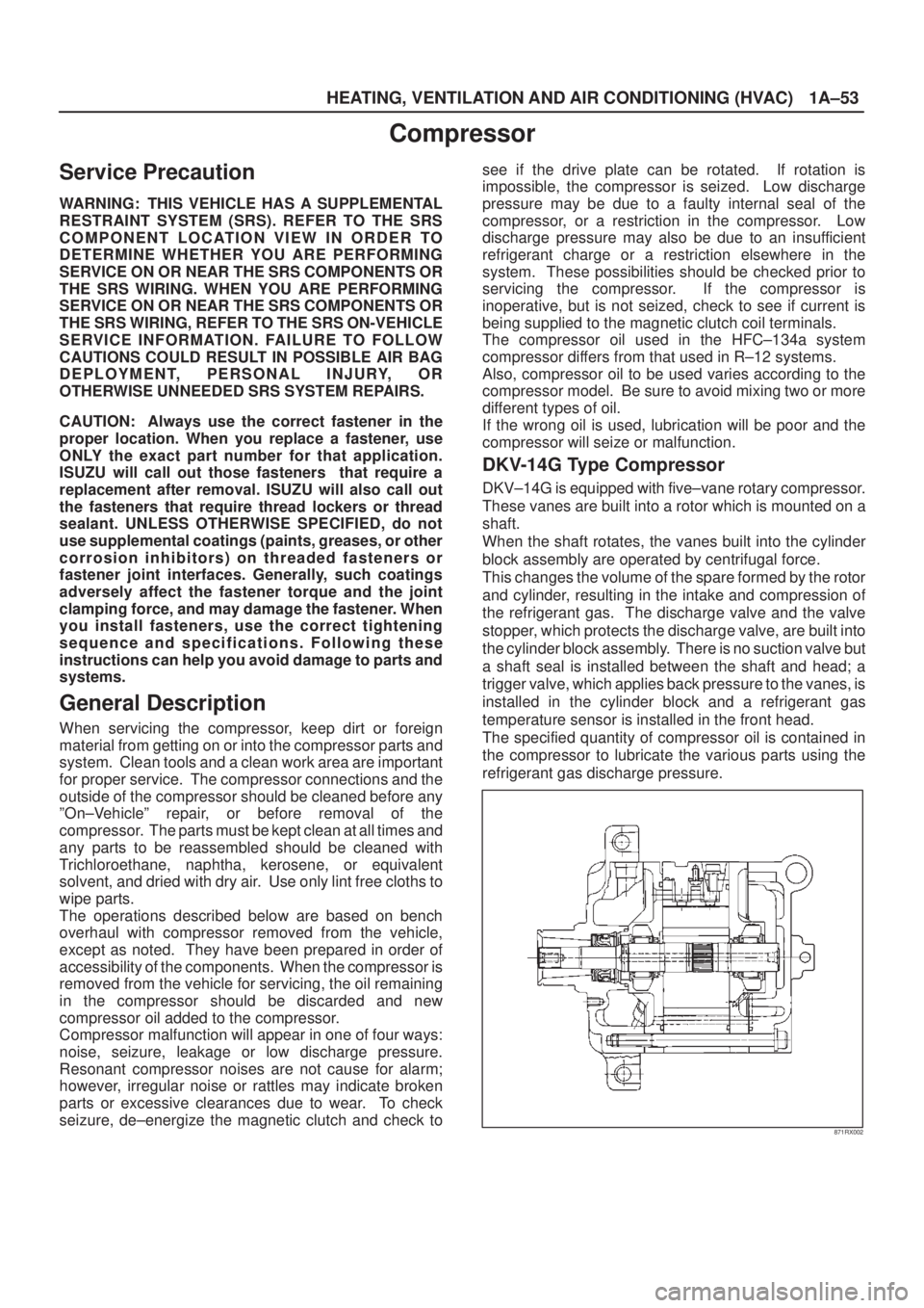
DKV±14G is equipped with five±vane rotary compressor.
These vanes are built into a rotor which is mounted on a
shaft.
When the shaft rotates, the vanes built into the cylinder
block assembly are operated by centrifugal force.
This changes the volume of the spare formed by the rotor
and cylinder, resulting in the intake and compression of
the refrigerant gas. The discharge valve and the valve
stopper, which protects the discharge valve, are built into
the cylinder block assembly. There is no suction valve but
a shaft seal is installed between the shaft and head; a
trigger valve, which applies back pressure to the vanes, is
installed in the cylinder block and a refrigerant gas
temperature sensor is installed in the front head.
The specified quantity of compressor oil is contained in
the compressor to lubricate the various parts using the
refrigerant gas discharge pressure.
871RX002
Page 153 of 2100
2A±2
POWER±ASSISTED STEERING SYSTEM
Service Precaution
WARNING: THIS VEHICLE HAS A SUPPLEMENTAL
RESTRAINT SYSTEM (SRS). REFER TO THE SRS
COMPONENT AND WIRING LOCATION VIEW IN
ORDER TO DETERMINE WHETHER YOU ARE
PERFORMING SERVICE ON OR NEAR THE SRS
COMPONENTS OR THE SRS WIRING. WHEN YOU
ARE PERFORMING SERVICE ON OR NEAR THE SRS
COMPONENTS OR THE SRS WIRING, REFER TO
THE SRS SERVICE INFORMATION. FAILURE TO
FOLLOW WARNINGS COULD RESULT IN POSSIBLE
AIR BAG DEPLOYMENT, PERSONAL INJURY, OR
OTHERWISE UNNEEDED SRS SYSTEM REPAIRS.
CAUTION: Always use the correct fastener in the
proper location. When you replace a fastener, use
ONLY the exact part number for that application.
ISUZU will call out those fasteners that require a
replacement after removal. ISUZU will also call out
the fasteners that require thread lockers or thread
sealant. UNLESS OTHERWISE SPECIFIED, do not
use supplemental coatings (Paints, greases, or other
corrosion inhibitors) on threaded fasteners or
fastener joint interfaces. Generally, such coatings
adversely affect the fastener torque and the joint
clamping force, and may damage the fastener. When
you install fasteners, use the correct tightening
sequence and specifications. Following these
instructions can help you avoid damage to parts and
systems.
Diagnosis
Since the problems in steering, suspension, wheels and
tires involve several systems, they must all be considered
when diagnosing a complaint. To identify the symptom,
always road test the vehicle first. Proceed with the follow-
ing preliminary inspections and correct any defects which
are found.
1. Inspect tires for proper pressure and uneven wear.
2. Raise vehicle on a hoist, then inspect front and rear
suspension and steering linkage for loose or
damaged parts.
3. Spin the front wheels. Inspect for out-of-round tires,
out-of-balance tires, loose and/or rough wheel
bearings.
General Diagnosis
ConditionPossible causeCorrection
Vehicle PullsMismatched or uneven tires.Replace tire.
Tires not adequately inflated.Adjust tire pressure.
Broken or sagging springs.Replace spring.
Radial tire lateral force.Replace tire.
Improper wheel alignment.Adjust wheel alignment.
Brake dragging in one wheel.Repair brake.
Loose, bent or broken front or rear
suspension parts.Tighten or replace the appropriate
suspension part(s).
Faulty shock absorbers.Replace shock absorber.
Parts in power steering valve
defective.Replace power steering unit.
Abnormal or Excessive Tire WearSagging or broken spring.Replace spring.
Tire out of balance.Balance or replace tire.
Improper wheel alignment.Check front end alignment.
Faulty shock absorber.Replace shock absorber.
Hard driving.Replace tire.
Overloaded vehicle.Replace tire and reduce load.
Tires not rotated periodically.Replace or rotate tire.
Worn or loose road wheel bearings.Replace wheel bearing.
Wobbly wheel or tires.Replace wheel or tire.
Tires not adequately inflated.Adjust the pressure.
Page 180 of 2100
POWER±ASSISTED STEERING SYSTEM2A±29
Supplemental Restraint System Steering Wheel & Column
Service Precaution
This steering wheel and column repair section covers the
Supplemental Restraint System (SRS) steering column.
The following repair procedures are specific to SRS
components. When servicing a vehicle equipped with
Supplemental Restraint System, pay close attention to all
WARNINGS and CAUTIONS.
For detailed explanation about SRS, refer to
Restraints
section.
WARNING: THIS VEHICLE HAS A SUPPLEMENTAL
RESTRAINT SYSTEM (SRS). REFER TO THE SRS
COMPONENT AND WIRING LOCATION VIEW IN
ORDER TO DETERMINE WHETHER YOU ARE
PERFORMING SERVICE ON OR NEAR THE SRS
COMPONENTS OR THE SRS WIRING. WHEN YOU
ARE PERFORMING SERVICE ON OR NEAR THE SRS
COMPONENTS OR THE SRS WIRING, REFER TO
THE SRS SERVICE INFORMATION. FAILURE TO
FOLLOW WARNINGS COULD RESULT IN POSSIBLE
AIR BAG DEPLOYMENT, PERSONAL INJURY, OR
OTHERWISE UNNEEDED SRS SYSTEM REPAIRS.
SAFE HANDLING OF INFLATOR MODULES
REQUIRES FOLLOWING THE PROCEDURES
DESCRIBED BELOW FOR BOTH LIVE AND
DEPLOYED MODULES.
SAFETY PRECAUTIONS MUST BE FOLLOWED
WHEN HANDLING A DEPLOYED AIR BAG
ASSEMBLY (AIR BAG). AFTER DEPLOYMENT, THE
AIR BAG ASSEMBLY (AIR BAG) SURFACE MAY
CONTAIN A SMALL AMOUNT OF SODIUM
HYDROXIDE, A BY-PRODUCT OF THE
DEPLOYMENT REACTION, THAT IS IRRITATING TO
THE SKIN AND EYES. MOST OF THE POWDER ON
THE AIR BAG ASSEMBLY (AIR BAG) IS HARMLESS.
AS A PRECAUTION, WEAR GLOVES AND SAFETY
GLASSES WHEN HANDLING A DEPLOYED AIR BAG
ASSEMBLY, AND WASH YOUR HANDS WITH MILD
SOAP AND WATER AFTERWARDS.WHEN CARRYING A LIVE AIR BAG ASSEMBLY,
MAKE SURE THE BAG AND TRIM COVER ARE
POINTED AWAY FROM YOU. NEVER CARRY AN AIR
BAG ASSEMBLY BY THE WIRES OR CONNECTOR
ON THE UNDERSIDE OF MODULE. IN THE CASE OF
AN ACCIDENTAL DEPLOYMENT, THE BAG WILL
THEN DEPLOY WITH MINIMAL CHANCE OF INJURY.
WHEN PLACING A LIVE AIR BAG ASSEMBLY ON A
BENCH OR OTHER SURFACE, ALWAYS FACE THE
BAG AND TRIM COVER UP, AWAY FROM THE
SURFACE.
NEVER REST A STEERING COLUMN ASSEMBLY ON
THE STEERING WHEEL WITH THE AIR BAG
ASSEMBLY FACE DOWN AND COLUMN VERTICAL.
THIS IS NECESSARY SO THAT A FREE SPACE IS
PROVIDED TO ALLOW THE AIR BAG ASSEMBLY TO
EXPAND IN THE UNLIKELY EVENT OF ACCIDENTAL
DEPLOYMENT. OTHERWISE, PERSONAL INJURY
COULD RESULT.
TO AVOID DEPLOYMENT WHEN
TROUBLESHOOTING THE SRS SYSTEM, DO NOT
USE ELECTRICAL TEST EQUIPMENT, SUCH AS
BATTERY-POWERED OR A/C-POWERED
VOLT-METER, OHMMETER, ETC., OR ANY TYPE OF
ELECTRICAL EQUIPMENT OTHER THAN
SPECIFIED IN THIS MANUAL. DO NOT USE A
NON-POWERED PROBE-TYPE TESTER.
INSTRUCTIONS IN THIS MANUAL MUST BE
FOLLOWED CAREFULLY, OTHERWISE PERSONAL
INJURY MAY RESULT.
SRS Connectors
CAUTION: The special yellow color connectors are
used for supplemental restraint system-air bag
circuit.
When removing the cable harness disconnect the
connector by unlocking at two places, outside (1)
and inside (2). Do not pull the wires or disconnection
may occur.
When connecting the double lock type SRS connec-
tor, insert the connector completely then lock the
connector. Imperfect locking may cause the SRS cir-
cuit to malfunction.
Page 189 of 2100
2A±38
POWER±ASSISTED STEERING SYSTEM
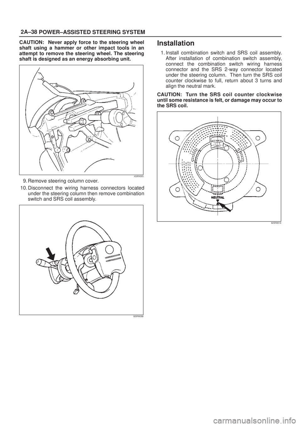
CAUTION: Never apply force to the steering wheel
shaft using a hammer or other impact tools in an
attempt to remove the steering wheel. The steering
shaft is designed as an energy absorbing unit.
430RX005
9. Remove steering column cover.
10. Disconnect the wiring harness connectors located
under the steering column then remove combination
switch and SRS coil assembly.
825RW288
Installation
1. Install combination switch and SRS coil assembly.
After installation of combination switch assembly,
connect the combination switch wiring harness
connector and the SRS 2-way connector located
under the steering column. Then turn the SRS coil
counter clockwise to full, return about 3 turns and
align the neutral mark.
CAUTION: Turn the SRS coil counter clockwise
until some resistance is felt, or damage may occur to
the SRS coil.
825RW016
Page 193 of 2100
2A±42
POWER±ASSISTED STEERING SYSTEM
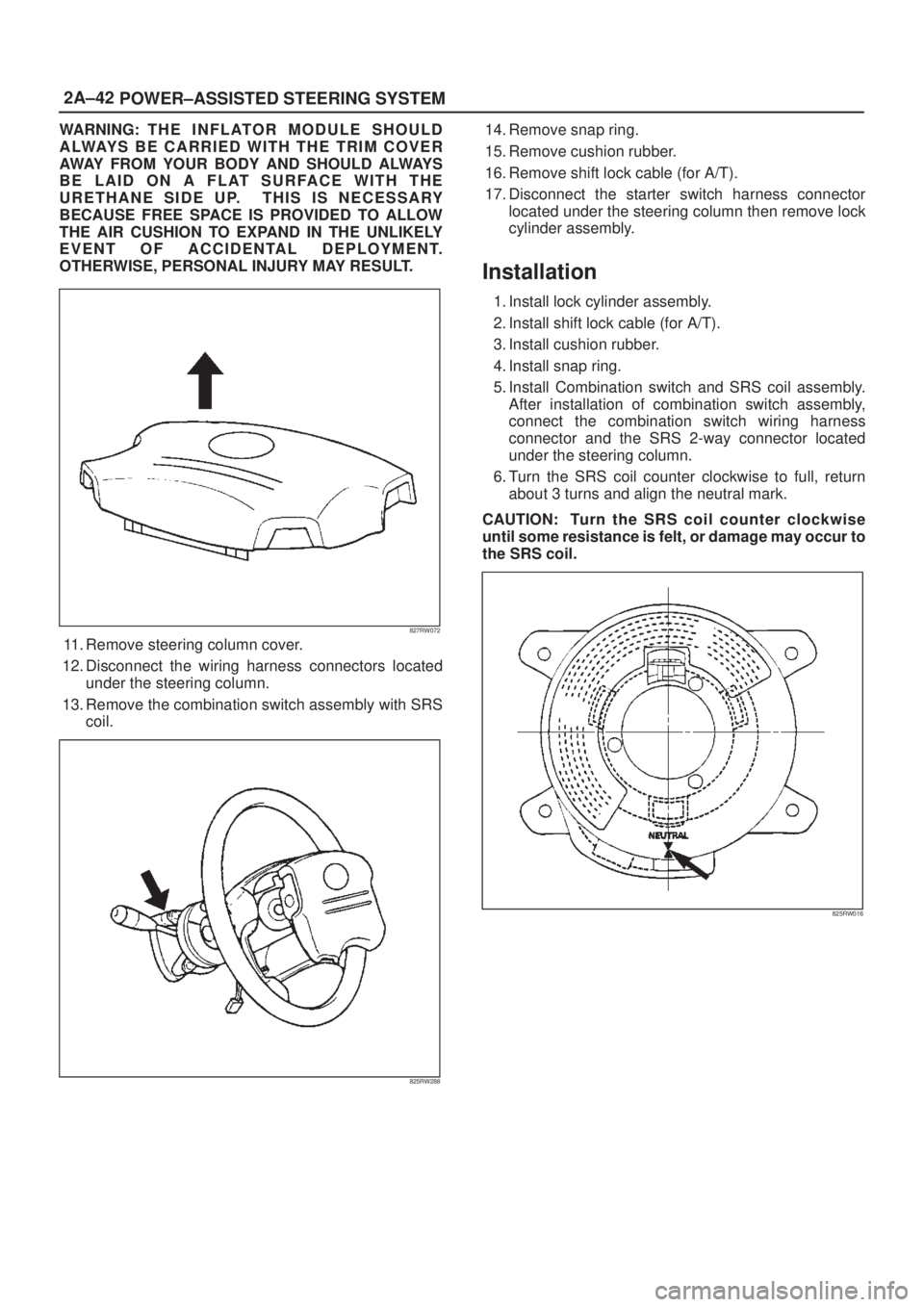
WARNING: T H E I N F L AT O R M O D U L E S H O U L D
ALWAYS BE CARRIED WITH THE TRIM COVER
AWAY FROM YOUR BODY AND SHOULD ALWAYS
BE LAID ON A FLAT SURFACE WITH THE
URETHANE SIDE UP. THIS IS NECESSARY
BECAUSE FREE SPACE IS PROVIDED TO ALLOW
THE AIR CUSHION TO EXPAND IN THE UNLIKELY
EVENT OF ACCIDENTAL DEPLOYMENT.
OTHERWISE, PERSONAL INJURY MAY RESULT.
827RW072
11. Remove steering column cover.
12. Disconnect the wiring harness connectors located
under the steering column.
13. Remove the combination switch assembly with SRS
coil.
825RW288
14. Remove snap ring.
15. Remove cushion rubber.
16. Remove shift lock cable (for A/T).
17. Disconnect the starter switch harness connector
located under the steering column then remove lock
cylinder assembly.
Installation
1. Install lock cylinder assembly.
2. Install shift lock cable (for A/T).
3. Install cushion rubber.
4. Install snap ring.
5. Install Combination switch and SRS coil assembly.
After installation of combination switch assembly,
connect the combination switch wiring harness
connector and the SRS 2-way connector located
under the steering column.
6. Turn the SRS coil counter clockwise to full, return
about 3 turns and align the neutral mark.
CAUTION: Turn the SRS coil counter clockwise
until some resistance is felt, or damage may occur to
the SRS coil.
825RW016
Page 194 of 2100
POWER±ASSISTED STEERING SYSTEM2A±43
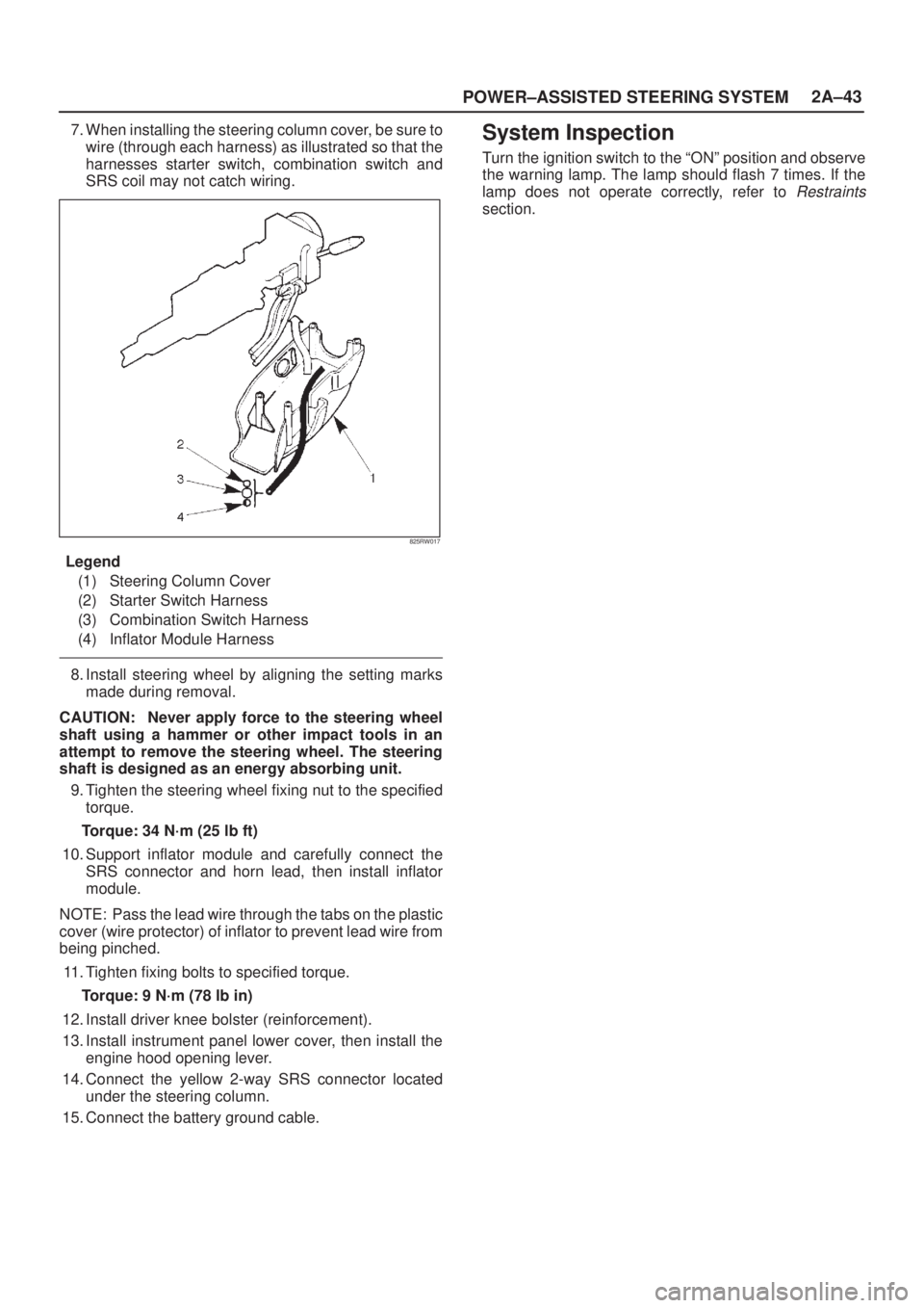
7. When installing the steering column cover, be sure to
wire (through each harness) as illustrated so that the
harnesses starter switch, combination switch and
SRS coil may not catch wiring.
825RW017
Legend
(1) Steering Column Cover
(2) Starter Switch Harness
(3) Combination Switch Harness
(4) Inflator Module Harness
8. Install steering wheel by aligning the setting marks
made during removal.
CAUTION: Never apply force to the steering wheel
shaft using a hammer or other impact tools in an
attempt to remove the steering wheel. The steering
shaft is designed as an energy absorbing unit.
9. Tighten the steering wheel fixing nut to the specified
torque.
Torque: 34 N´m (25 lb ft)
10. Support inflator module and carefully connect the
SRS connector and horn lead, then install inflator
module.
NOTE: Pass the lead wire through the tabs on the plastic
cover (wire protector) of inflator to prevent lead wire from
being pinched.
11. Tighten fixing bolts to specified torque.
Torque: 9 N´m (78 lb in)
12. Install driver knee bolster (reinforcement).
13. Install instrument panel lower cover, then install the
engine hood opening lever.
14. Connect the yellow 2-way SRS connector located
under the steering column.
15. Connect the battery ground cable.
System Inspection
Turn the ignition switch to the ªONº position and observe
the warning lamp. The lamp should flash 7 times. If the
lamp does not operate correctly, refer to
Restraints
section.
Page 196 of 2100
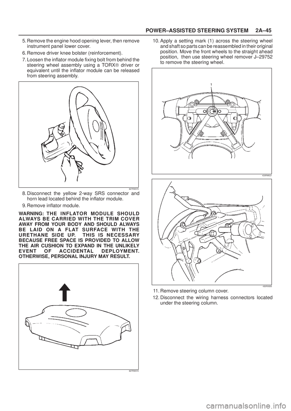
POWER±ASSISTED STEERING SYSTEM2A±45
5. Remove the engine hood opening lever, then remove
instrument panel lower cover.
6. Remove driver knee bolster (reinforcement).
7. Loosen the inflator module fixing bolt from behind the
steering wheel assembly using a TORX) driver or
equivalent until the inflator module can be released
from steering assembly.
827RW070
8. Disconnect the yellow 2-way SRS connector and
horn lead located behind the inflator module.
9. Remove inflator module.
WARNING: T H E I N F L AT O R M O D U L E S H O U L D
ALWAYS BE CARRIED WITH THE TRIM COVER
AWAY FROM YOUR BODY AND SHOULD ALWAYS
BE LAID ON A FLAT SURFACE WITH THE
URETHANE SIDE UP. THIS IS NECESSARY
BECAUSE FREE SPACE IS PROVIDED TO ALLOW
THE AIR CUSHION TO EXPAND IN THE UNLIKELY
EVENT OF ACCIDENTAL DEPLOYMENT.
OTHERWISE, PERSONAL INJURY MAY RESULT.
827RW072
10. Apply a setting mark (1) across the steering wheel
and shaft so parts can be reassembled in their original
position. Move the front wheels to the straight ahead
position, then use steering wheel remover J±29752
to remove the steering wheel.
430RW021
430RX005
11. Remove steering column cover.
12. Disconnect the wiring harness connectors located
under the steering column.