mileage ISUZU TF SERIES 2004 User Guide
[x] Cancel search | Manufacturer: ISUZU, Model Year: 2004, Model line: TF SERIES, Model: ISUZU TF SERIES 2004Pages: 4264, PDF Size: 72.63 MB
Page 2240 of 4264

6E-244 3.5L ENGINE DRIVEABILITY AND EMISSIONS
CIRCUIT DESCRIPTION
If the ECM receives an incorrect number of pulses on
the CMP reference circuit, DTC P0341 will set.
If the ECM does not receive pulses on the CMP
reference circuit, DTC P0342 will set.
DIAGNOSTIC AIDS
An intermittent may be caused by a poor connection,
rubbed–through wire insulation or a wire broken inside
the insulation. Check for:
Poor connection —Inspect the ECM harness and
connectors for improper mating, broken locks,
improperly formed or damaged terminals, and poo
r
terminal-to-wire connection.
Damaged harness —Inspect the wiring harness fo
r
damage.
Reviewing the Failure Records vehicle mileage since
the diagnostic test last failed may help determine ho
w
often the condition that caused the DTC to be se
t
occurs. This may assist in diagnosing the condition.
Diagnostic Trouble Code (DTC) P0341(Flash Code 41) Camshaft
Position Sensor Circuit Range/Performance
Diagnostic Trouble Code (DTC) P0342 (Flash Code 41) Camshaft
Position Sensor Circuit No Signal
Step Action Value (s) Yes No
1
Was the "On-Board Diagnostic (OBD) System Check"
performed?
- Go to Step 2 Go to On Board
Diagnostic (OBD)
System Check
2
1. Connect the Tech 2.
2. Review and record the failure information.
3. Select "F0: Read DTC Infor By Priority" in "F0:
Diagnostic Trouble Code".
Is the DTC P0341 or P0342 stored as "Present
Failure"?
- Go to Step 3 Refer to
Diagnostic Aids
and Go to Step 3
3
1. Using the Tech2, ignition "On" and engine "Off".
2. Select "Clear DTC Information" with the Tech2 and
clear the DTC information.
3. Operate the vehicle and monitor the "F5: Failed
This Ignition" in "F2: DTC Information"
Was the DTC P0341 or P0342 stored in this ignition
cycle?
- Go to Step 4 Refer to
Diagnostic Aids
and Go to Step 4
4
Check any accessory parts which may cause electric
interference or magnetic interference.
Was the problem found?
- Remove the
accessory parts
and verify repair Go to Step 5
Page 2246 of 4264

6E-250 3.5L ENGINE DRIVEABILITY AND EMISSIONS
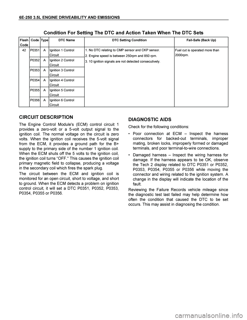
Condition For Setting The DTC and Action Taken When The DTC Sets
Flash
Code Code Type DTC Name DTC Setting Condition Fail-Safe (Back Up)
P0351 A Ignition 1 Control
Circuit
P0352 A Ignition 2 Control
Circuit
P0353 A Ignition 3 Control
Circuit
P0354 A Ignition 4 Control
Circuit
P0355 A Ignition 5 Control
Circuit
42
P0356 A Ignition 6 Control
Circuit 1. No DTC relating to CMP sensor and CKP sensor.
2. Engine speed is between 250rpm and 850 rpm.
3. 10 ignition signals are not detected consecutively. Fuel cut is operated more than
2000rpm.
CIRCUIT DESCRIPTION
The Engine Control Module's (ECM) control circuit 1
provides a zero-volt or a 5-volt output signal to the
ignition coil. The normal voltage on the circuit is zero
volts. When the ignition coil receives the 5-volt signal
from the ECM, it provides a ground path for the B+
supply to the primary side of the number 1 ignition coil.
When the ECM shuts off the 5 volts to the ignition coil,
the ignition coil turns “OFF." This causes the ignition coil
primary magnetic field to collapse, producing a voltage
in the secondary coil which fires the spark plug.
The circuit between the ECM and ignition coil is
monitored for an open circuit, short to voltage, and shor
t
to ground. When the ECM detects a problem on ignition
control circuit, it will set a DTC P0351, P0352, P0353,
P0354, P0355 or P0356.
DIAGNOSTIC AIDS
Check for the following conditions:
Poor connection at ECM – Inspect the harness
connectors for backed-out terminals, imprope
r
mating, broken locks, improperly formed or damaged
terminals, and poor terminal-to-wire connections.
Damaged harness –Inspect the wiring harness fo
r
damage. If the harness appears to be OK, observe
the Tech 2 display related to DTC P0351 or P0352,
P0353, P0354, P0355 or P0356 while moving the
connector and wiring related to the ignition system.
A
change in the display will indicate the location of the
fault.
Reviewing the Failure Records vehicle mileage since
the diagnostic test last failed may help determine ho
w
often the condition that caused the DTC to be set
occurs. This may assist in diagnosing the condition.
Page 2271 of 4264

3.5L ENGINE DRIVEABILITY AND EMISSIONS 6E-275
CIRCUIT DESCRIPTION
The canister purge solenoid valve is controlled by the
Engine Train Control Module (ECM).
At an appropriate time, the EVAP canister purge
solenoid is “ON," allowing engine vacuum to draw a
small vacuum on the entire evaporative emissions
system.
DIAGNOSTIC AIDS
An intermittent may be caused by the following:
Poor connections.
Mis routed harness.
Rubbed through wire insulation.
Broken wire inside the insulation.
Check for the following conditions:
Poor connection at ECM-Inspect harness connectors
for backed out terminals, improper mating, broken
locks, improperly formed or damaged terminals, and
poor terminal to wire connection.
Damaged harness-Inspect the wiring harness fo
r
damage. If the harness appears to be OK, observe
the EVAP purge solenoid display on the Tech 2 while
moving connectors and wiring harnesses related to
the sensor.
A change in the display will indicate the location o
f
the fault. If DTC P0444 or P0445 cannot be
duplicated, the information included in the Failure
Records data can be useful in determined vehicle
mileage since the DTC was last set.
If it is determined that the DTC occurs intermittently,
performing the DTC P0444 or P0445 Diagnostic
Chart may isolate the cause of the fault.
Diagnostic Trouble Code (DTC) P0444 EVAP Purge Solenoid
Valve Circuit Low Voltage
Diagnostic Trouble Code (DTC) P0445 EVAP Purge Solenoid
Valve Circuit High Voltage
Step Action Value (s) Yes No
1
Was the "On-Board Diagnostic (OBD) System Check"
performed?
- Go to Step 2 Go to On Board
Diagnostic (OBD)
System Check
2
1. Connect the Tech 2.
2. Review and record the failure information.
3. Select "F0: Read DTC Infor By Priority" in "F0:
Diagnostic Trouble Code".
Is the DTC P0444 or P0445 stored as "Present
Failure"?
- Go to Step 3 Refer to
Diagnostic Aids
and Go to Step 3
3
1. Using the Tech2, ignition "On" and engine "Off".
2. Select "Clear DTC Information" with the Tech2 and
clear the DTC information.
3. Operate the vehicle and monitor the "F5: Failed
This Ignition" in "F2: DTC Information"
Was the DTC P0444 or P0445 stored in this ignition
cycle?
- Go to Step 4 Refer to
Diagnostic Aids
and Go to Step 4
Page 2441 of 4264

ENGINE MECHANICAL (C24SE) 6A-21
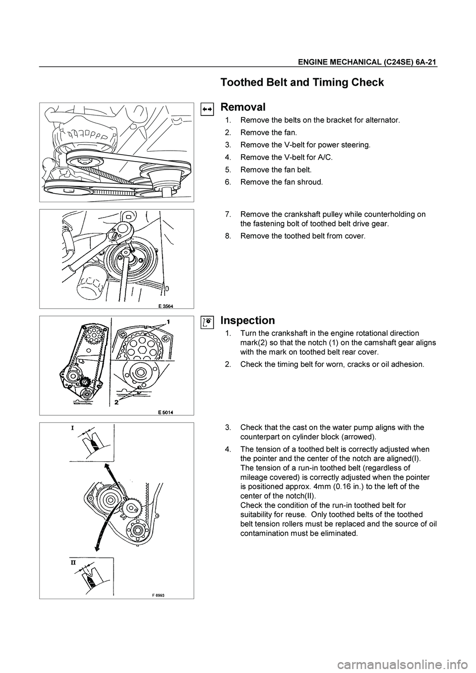
Toothed Belt and Timing Check
Removal
1. Remove the belts on the bracket for alternator.
2. Remove the fan.
3. Remove the V-belt for power steering.
4. Remove the V-belt for A/C.
5. Remove the fan belt.
6. Remove the fan shroud.
7. Remove the crankshaft pulley while counterholding on
the fastening bolt of toothed belt drive gear.
8. Remove the toothed belt from cover.
Inspection
1. Turn the crankshaft in the engine rotational direction
mark(2) so that the notch (1) on the camshaft gear aligns
with the mark on toothed belt rear cover.
2. Check the timing belt for worn, cracks or oil adhesion.
3. Check that the cast on the water pump aligns with the
counterpart on cylinder block (arrowed).
4. The tension of a toothed belt is correctly adjusted when
the pointer and the center of the notch are aligned(I).
The tension of a run-in toothed belt (regardless of
mileage covered) is correctly adjusted when the pointer
is positioned approx. 4mm (0.16 in.) to the left of the
center of the notch(II).
Check the condition of the run-in toothed belt for
suitability for reuse. Only toothed belts of the toothed
belt tension rollers must be replaced and the source of oil
contamination must be eliminated.