lock ISUZU TFR SERIES 1997 Workshop Manual
[x] Cancel search | Manufacturer: ISUZU, Model Year: 1997, Model line: TFR SERIES, Model: ISUZU TFR SERIES 1997Pages: 1800, PDF Size: 91.06 MB
Page 1046 of 1800

14
3. Transponder
If a transponder key is lost;
All transponder keys in the immobilizer control system must be erased. Transponder keys can be ordered via
the "Your proper organization name such as Parts and accessory department" as previously by providing the
mechanical key number.
The mechanical key number is provided on the car pass.
Thereafter, existing and new transponder keys are programmed consecutively using Tech 2. The vehicle can
then no longer be started using lost key.
5 transponder keys can be provided:
Each transponder has different Identifications. If a customer wants more than 2 transponder keys, maximum to
5 transponder keys can be provided by additional programming by Tech 2.
lf a new ignition key with different mechanical key number needs to be installed;
If installation of an ignition lock with a different mechanism key number is necessary (an ignition lock which
belongs to the mechanical key number has to be ordered first), all transponder keys must first be erased and
the two transponder keys which belong to the ignition lock that is now installed must be programmed.
The new mechanical key number must be programmed now into the immobilizer. The mechanical key number
in the car pass is to be changed as well.
Transponder program
1. Connect Tech 2, select "Body" and "Immobilizer".
2. Select program TP-Key mode.
3. See immobilizer status on Tech 2 screen, and enter security code. If the status does not allow the
programming, only immobilizer status is displayed.
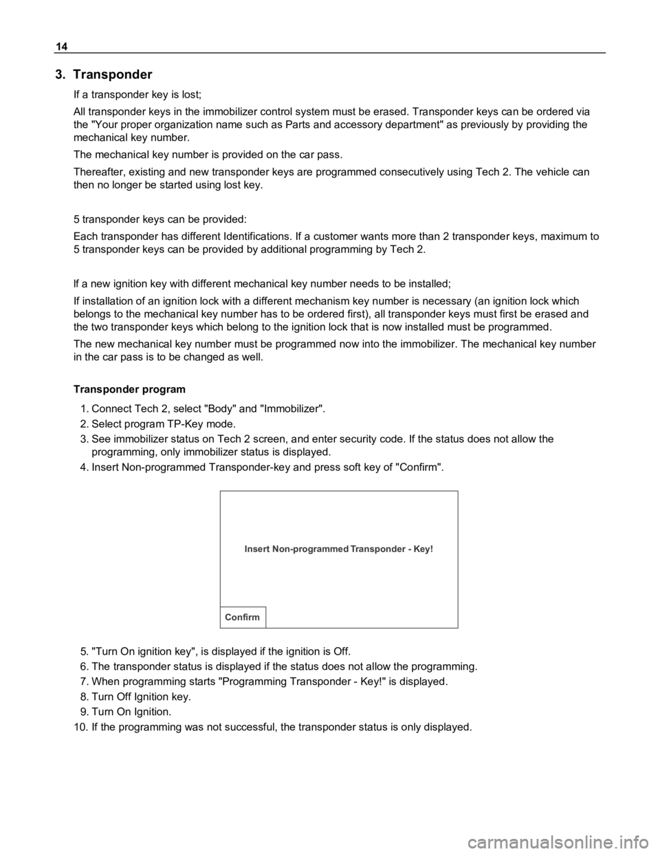
4. Insert Non-programmed Transponder-key and press soft key of "Confirm".
Insert Non-programmed Transponder - Key!
Confirm
5. "Turn On ignition key", is displayed if the ignition is Off.
6. The transponder status is displayed if the status does not allow the programming.
7. When programming starts "Programming Transponder - Key!" is displayed.
8. Turn Off Ignition key.
9. Turn On Ignition.
10. If the programming was not successful, the transponder status is only displayed.
Page 1062 of 1800

30
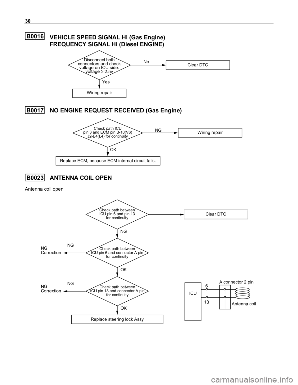
B0016VEHICLE SPEED SIGNAL Hi (Gas Engine)
FREQUENCY SIGNAL Hi (Diesel ENGINE)
Disconnect both
connectors and check
voltage on ICU side.
voltage
2.5v
W iring repairYesNo
Clear DTC
B0017NO ENGINE REQUEST RECEIVED (Gas Engine)
Check path ICU
pin 3 and ECM pin B-18(V6)
J2-B4(L4) for continuity
Replace ECM, because ECM internal circuit fails.OK
W iring repair NG
B0023ANTENNA COIL OPEN
Antenna coil open
Check path between
ICU pin 6 and pin 13
for continuity
Replace steering lock AssyNG
Clear DTC
OK OK
Check path between
ICU pin 6 and connector A pin
for continuity
Check path between
ICU pin 13 and connector A pin
for continuity
ICU
A connector 2 pin
6
13
Antenna coil NG
Correction
NG
NG
CorrectionNG
Page 1066 of 1800

34
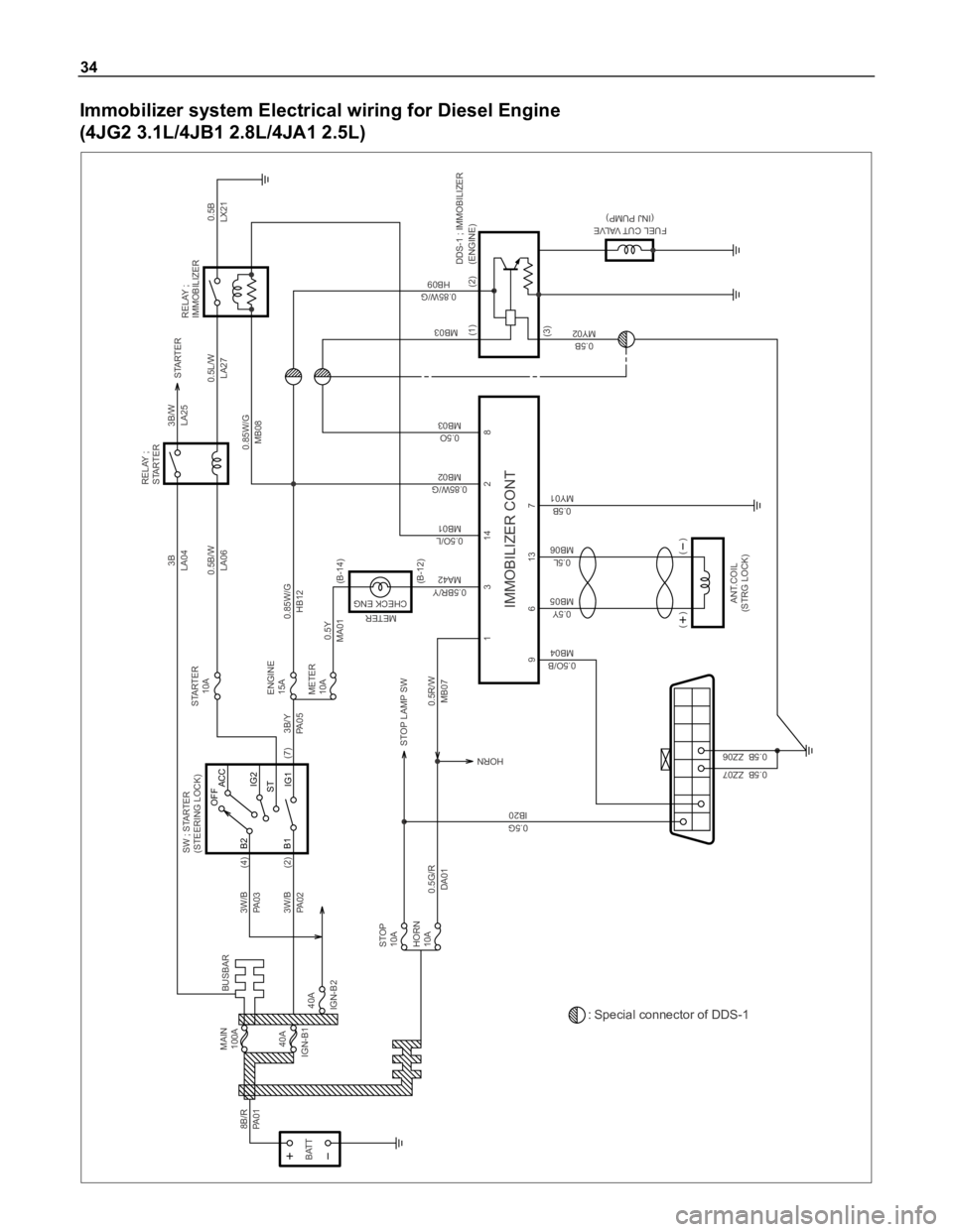
Immobilizer system Electrical wiring for Diesel Engine
(4JG2 3.1L/4JB1 2.8L/4JA1 2.5L)
BATT3W/B
PA 0 3(4)
3W/B
PA 0 2
0.5G/R
DA010.5Y
MA010.5B/W
LA060.5L/W
LA27
0.85W/G
MB080.5B
LX21 3B
LA043B/W
LA25
3B/Y
PA 0 50.85W/G
HB12
0.5R/W
MB07 STOP LAMP SW
0.5G
IB20
0.5B ZZ07
0.5B ZZ06
0.5O/B
MB04HORN
9 (2)
MAIN
100A
STOP
10AENGINE
15A
METER
10A40A
IGN-B1 8B/R
PA 0 1
B2
B1ACC OFF
IG2
IG1 STSW ; STARTER
(STEERING LOCK)RELAY ;
STARTER
40A
IGN-B2
HORN
10A
0.5Y
MB056
0.5L
MB0613
0.5B
MY017
0.5B
MY02
FUEL CUT VALVE
(INJ PUMP)MB03
0.85W/G
HB09
1
0.5BR/Y
MA423
0.5O/L
MB0114
0.85W/G
MB022
0.5O
MB038
ANT.COIL
(STRG LOCK)
( )
( )
STARTER
IMMOBILIZER CONT
(3)(1) (2)
RELAY ;
IMMOBILIZER
STARTER
10A
(7)
METER
CHECK ENG
BUSBAR
(B-14)
(B-12)
DDS-1 ; IMMOBILIZER
(ENGINE)
: Special connector of DDS-1