Transmission ISUZU TROOPER 1998 Service User Guide
[x] Cancel search | Manufacturer: ISUZU, Model Year: 1998, Model line: TROOPER, Model: ISUZU TROOPER 1998Pages: 3573, PDF Size: 60.36 MB
Page 131 of 3573
AIR CONDITIONING 1B Ð 5
With some compressors the differential between
the intake pressure and discharge pressure
generated while the compressor is operating is
used for lubrication instead of an oil pump.
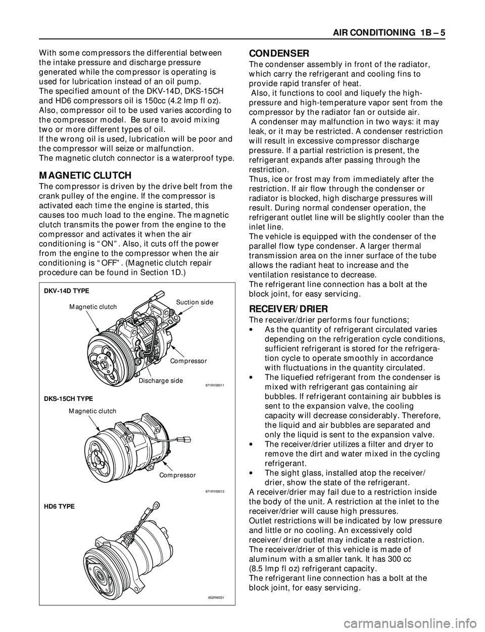
The specified amount of the DKV-14D, DKS-15CH
and HD6 compressors oil is 150cc (4.2 Imp fl oz).
Also, compressor oil to be used varies according to
the compressor model. Be sure to avoid mixing
two or more different types of oil.
If the wrong oil is used, lubrication will be poor and
the compressor will seize or malfunction.
The magnetic clutch connector is a waterproof type.
MAGNETIC CLUTCH
The compressor is driven by the drive belt from the
crank pulley of the engine. If the compressor is
activated each time the engine is started, this
causes too much load to the engine. The magnetic
clutch transmits the power from the engine to the
compressor and activates it when the air
conditioning is ÒONÓ. Also, it cuts off the power
from the engine to the compressor when the air
conditioning is ÒOFFÓ. (Magnetic clutch repair
procedure can be found in Section 1D.)
CONDENSER
The condenser assembly in front of the radiator,
which carry the refrigerant and cooling fins to
provide rapid transfer of heat.
Also, it functions to cool and liquefy the high-
pressure and high-temperature vapor sent from the
compressor by the radiator fan or outside air.
A condenser may malfunction in two ways: it may
leak, or it may be restricted. A condenser restriction
will result in excessive compressor discharge
pressure. If a partial restriction is present, the
refrigerant expands after passing through the
restriction.
Thus, ice or frost may from immediately after the
restriction. If air flow through the condenser or
radiator is blocked, high discharge pressures will
result. During normal condenser operation, the
refrigerant outlet line will be slightly cooler than the
inlet line.
The vehicle is equipped with the condenser of the
parallel flow type condenser. A larger thermal
transmission area on the inner surface of the tube
allows the radiant heat to increase and the
ventilation resistance to decrease.
The refrigerant line connection has a bolt at the
block joint, for easy servicing.
RECEIVER/DRIER
The receiver/drier performs four functions;
·As the quantity of refrigerant circulated varies
depending on the refrigeration cycle conditions,
sufficient refrigerant is stored for the refrigera-
tion cycle to operate smoothly in accordance
with fluctuations in the quantity circulated.
·The liquefied refrigerant from the condenser is
mixed with refrigerant gas containing air
bubbles. If refrigerant containing air bubbles is
sent to the expansion valve, the cooling
capacity will decrease considerably. Therefore,
the liquid and air bubbles are separated and
only the liquid is sent to the expansion valve.
·The receiver/drier utilizes a filter and dryer to
remove the dirt and water mixed in the cycling
refrigerant.
·The sight glass, installed atop the receiver/
drier, show the state of the refrigerant.
A receiver/drier may fail due to a restriction inside
the body of the unit. A restriction at the inlet to the
receiver/drier will cause high pressures.
Outlet restrictions will be indicated by low pressure
and little or no cooling. An excessively cold
receiver/ drier outlet may indicate a restriction.
The receiver/drier of this vehicle is made of
aluminum with a smaller tank. It has 300 cc
(8.5 Imp fl oz) refrigerant capacity.
The refrigerant line connection has a bolt at the
block joint, for easy servicing.
DKV-14D TYPE
DKS-15CH TYPE
HD6 TYPE
Magnetic clutch
CompressorSuction side
Discharge side
Compressor Magnetic clutch
852RW031 871RY00012
871RY00011
Page 363 of 3573
SUPPLEMENTAL RESTRAINT SYSTEM STEERING WHEEL & COLUMN 2A – 61
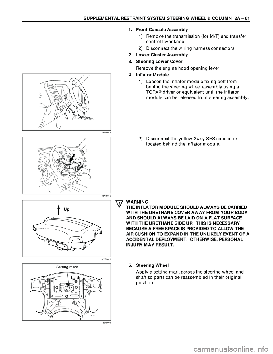
1. Front Console Assembly
1) Remove the transmission (for M/T) and transfer
control lever knob.
2) Disconnect the wiring harness connectors.
2. Lower Cluster Assembly
3. Steering Lower Cover
Remove the engine hood opening lever.
4. Inflator Module
1) Loosen the inflator module fixing bolt from
behind the steering wheel assembly using a
TORX
driver or equivalent until the inflator
module can be released from steering assembly.
2) Disconnect the yellow 2way SRS connector
located behind the inflator module.
WARNING
THE INFLATOR MODULE SHOULD ALWAYS BE CARRIED
WITH THE URETHANE COVER AWAY FROM YOUR BODY
AND SHOULD ALWAYS BE LAID ON A FLAT SURFACE
WITH THE URETHANE SIDE UP. THIS IS NECESSARY
BECAUSE A FREE SPACE IS PROVIDED TO ALLOW THE
AIR CUSHION TO EXPAND IN THE UNLIKELY EVENT OF A
ACCIDENTAL DEPLOYMENT. OTHERWISE, PERSONAL
INJURY MAY RESULT.
5. Steering Wheel
Apply a setting mark across the steering wheel and
shaft so parts can be reassembled in their original
position.
827RS014
827RS015
827RS016
Up
430RS004
Setting mark
Page 365 of 3573
SUPPLEMENTAL RESTRAINT SYSTEM STEERING WHEEL & COLUMN 2A Ð 63
5. Steering Wheel
Align the setting marks made when removing.
CAUTION:
Never apply force to the steering wheel in direction of the
shaft by using a hammer or other impact tools in an
attempt to remove the steering wheel. The steering shaft
is designed as an energy absorbing unit.
Tighten the steering wheel fixing nut to the specified
torque.
Steering Wheel Nut Torque Nám (kgám/lbáft)
34 (3.5 / 25)
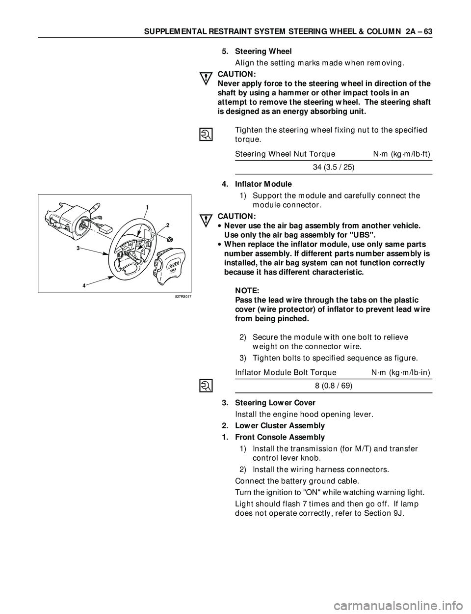
4. Inflator Module
1) Support the module and carefully connect the
module connector.
CAUTION:
·Never use the air bag assembly from another vehicle.
Use only the air bag assembly for "UBS".
·When replace the inflator module, use only same parts
number assembly. If different parts number assembly is
installed, the air bag system can not function correctly
because it has different characteristic.
NOTE:
Pass the lead wire through the tabs on the plastic
cover (wire protector) of inflator to prevent lead wire
from being pinched.
2) Secure the module with one bolt to relieve
weight on the connector wire.
3) Tighten bolts to specified sequence as figure.
Inflator Module Bolt Torque Nám (kgám/lbáin)
8 (0.8 / 69)
3. Steering Lower Cover
Install the engine hood opening lever.
2. Lower Cluster Assembly
1. Front Console Assembly
1) Install the transmission (for M/T) and transfer
control lever knob.
2) Install the wiring harness connectors.
Connect the battery ground cable.
Turn the ignition to "ON" while watching warning light.
Light should flash 7 times and then go off. If lamp
does not operate correctly, refer to Section 9J.
3
41
2
827RS017
Page 367 of 3573
SUPPLEMENTAL RESTRAINT SYSTEM STEERING WHEEL & COLUMN 2A – 65
CAUTION:
The wheels of the vehicle must be straight ahead and the
steering column in the "LOCK" position before
disconnecting the steering wheel. Failure to do so will
cause the coil assembly to become uncentered which will
cause damage to the coil assembly.
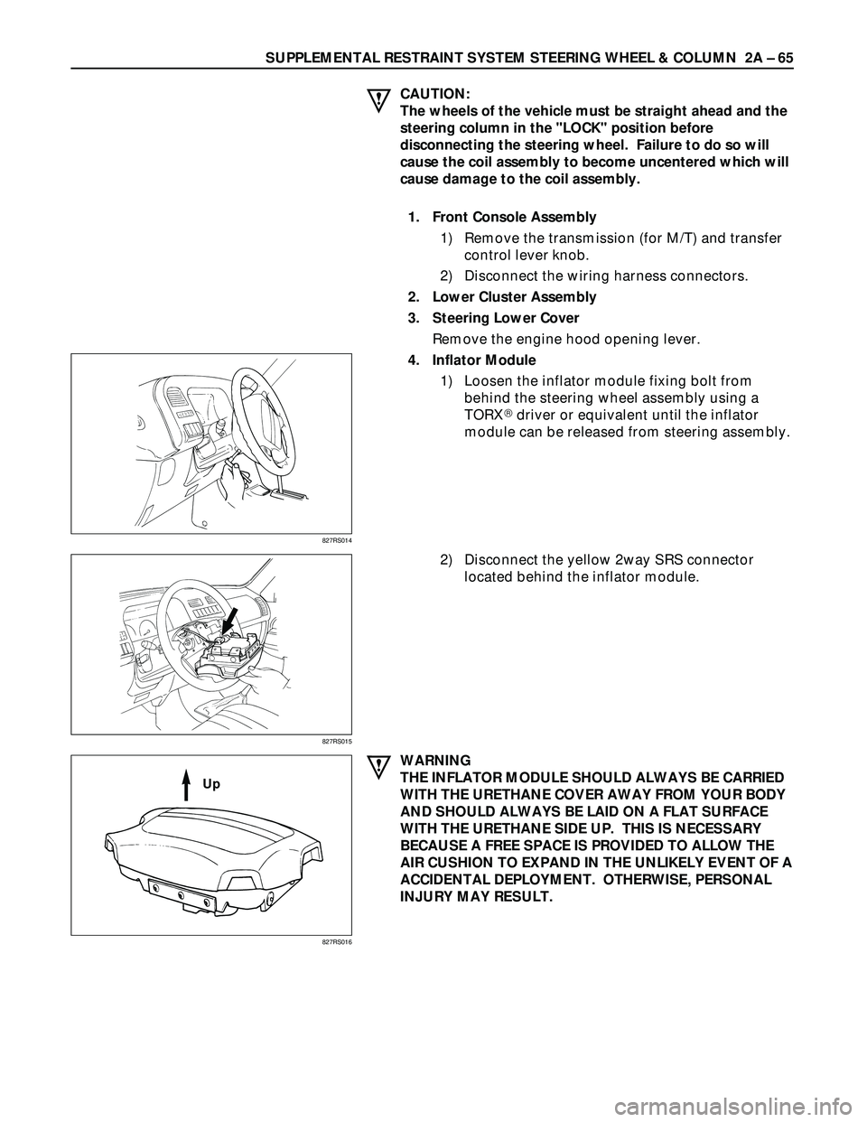
1. Front Console Assembly
1) Remove the transmission (for M/T) and transfer
control lever knob.
2) Disconnect the wiring harness connectors.
2. Lower Cluster Assembly
3. Steering Lower Cover
Remove the engine hood opening lever.
4. Inflator Module
1) Loosen the inflator module fixing bolt from
behind the steering wheel assembly using a
TORX
driver or equivalent until the inflator
module can be released from steering assembly.
2) Disconnect the yellow 2way SRS connector
located behind the inflator module.
WARNING
THE INFLATOR MODULE SHOULD ALWAYS BE CARRIED
WITH THE URETHANE COVER AWAY FROM YOUR BODY
AND SHOULD ALWAYS BE LAID ON A FLAT SURFACE
WITH THE URETHANE SIDE UP. THIS IS NECESSARY
BECAUSE A FREE SPACE IS PROVIDED TO ALLOW THE
AIR CUSHION TO EXPAND IN THE UNLIKELY EVENT OF A
ACCIDENTAL DEPLOYMENT. OTHERWISE, PERSONAL
INJURY MAY RESULT.
827RS014
827RS015
827RS016
Up
Page 370 of 3573
2A Ð 68 SUPPLEMENTAL RESTRAINT SYSTEM STEERING WHEEL & COLUMN
3
41
2
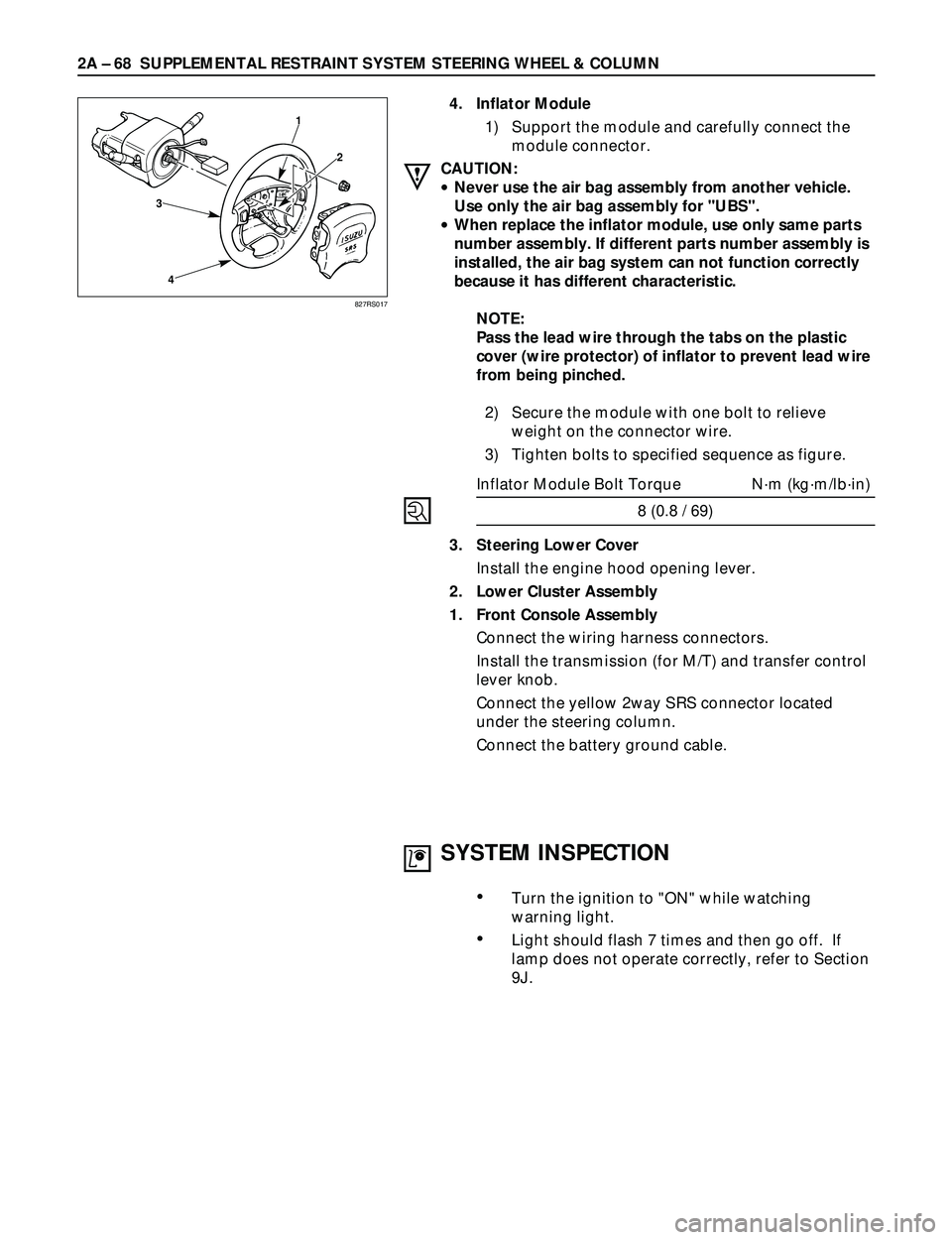
4. Inflator Module
1) Support the module and carefully connect the
module connector.
CAUTION:
·Never use the air bag assembly from another vehicle.
Use only the air bag assembly for "UBS".
·When replace the inflator module, use only same parts
number assembly. If different parts number assembly is
installed, the air bag system can not function correctly
because it has different characteristic.
NOTE:
Pass the lead wire through the tabs on the plastic
cover (wire protector) of inflator to prevent lead wire
from being pinched.
2) Secure the module with one bolt to relieve
weight on the connector wire.
3) Tighten bolts to specified sequence as figure.
Inflator Module Bolt Torque Nám (kgám/lbáin)
8 (0.8 / 69)
3. Steering Lower Cover
Install the engine hood opening lever.
2. Lower Cluster Assembly
1. Front Console Assembly
Connect the wiring harness connectors.
Install the transmission (for M/T) and transfer control
lever knob.
Connect the yellow 2way SRS connector located
under the steering column.
Connect the battery ground cable.
827RS017
SYSTEM INSPECTION
¥Turn the ignition to "ON" while watching
warning light.
¥Light should flash 7 times and then go off. If
lamp does not operate correctly, refer to Section
9J.
Page 372 of 3573
2A – 70 SUPPLEMENTAL RESTRAINT SYSTEM STEERING WHEEL & COLUMN
REMOVAL
Preparation:
1) Turn the steering wheel so that the vehicle's wheels
are pointing straight ahead.
2) Turn the ignition switch to "LOCK".
3) Disconnect the battery ground cable, and wait at least
5 minutes.
4) Disconnect the yellow 2way SRS connector located
under the steering column.
CAUTION:
The wheels of the vehicle must be straight ahead and the
steering column in the "LOCK" position before
disconnecting the steering wheel.
Failure to do so will cause the SRS coil assembly to
become uncentered which will cause damage to the SRS
coil assembly.
1. Front Console Assembly
Disconnect the transmission (for M/T) and transfer
control lever knob.
Disconnect the wiring harness connectors.
2. Lower Cluster Assembly
3. Steering Lower Cover
Remove the engine hood opening lever.
4. Driver Knee Bolster (Reinforcement)
5. Inflator Module
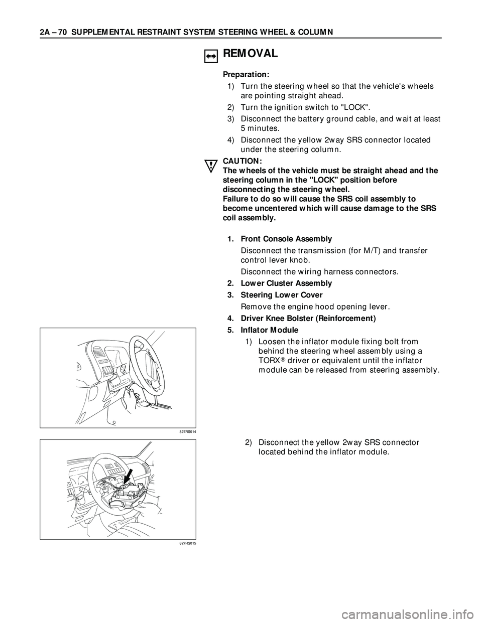
1) Loosen the inflator module fixing bolt from
behind the steering wheel assembly using a
TORX
driver or equivalent until the inflator
module can be released from steering assembly.
2) Disconnect the yellow 2way SRS connector
located behind the inflator module.
827RS014
827RS015
Page 375 of 3573
SUPPLEMENTAL RESTRAINT SYSTEM STEERING WHEEL & COLUMN 2A Ð 73
Starter switch
harness
Combination
switch harness
Inflator module
harness
Setting cowl
(Lower)
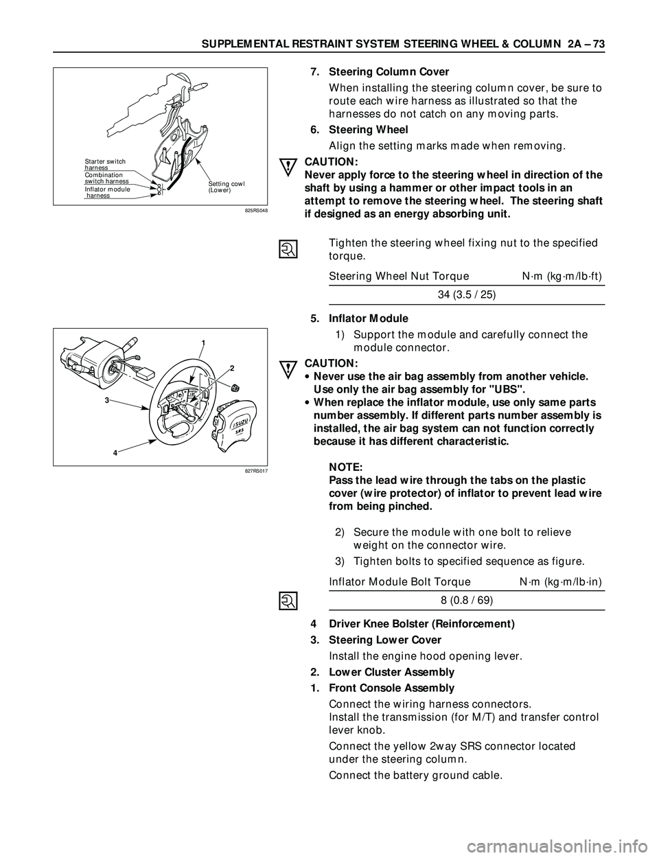
7. Steering Column Cover
When installing the steering column cover, be sure to
route each wire harness as illustrated so that the
harnesses do not catch on any moving parts.
6. Steering Wheel
Align the setting marks made when removing.
CAUTION:
Never apply force to the steering wheel in direction of the
shaft by using a hammer or other impact tools in an
attempt to remove the steering wheel. The steering shaft
if designed as an energy absorbing unit.
Tighten the steering wheel fixing nut to the specified
torque.
Steering Wheel Nut Torque Nám (kgám/lbáft)
34 (3.5 / 25)
5. Inflator Module
1) Support the module and carefully connect the
module connector.
CAUTION:
·Never use the air bag assembly from another vehicle.
Use only the air bag assembly for "UBS".
·When replace the inflator module, use only same parts
number assembly. If different parts number assembly is
installed, the air bag system can not function correctly
because it has different characteristic.
NOTE:
Pass the lead wire through the tabs on the plastic
cover (wire protector) of inflator to prevent lead wire
from being pinched.
2) Secure the module with one bolt to relieve
weight on the connector wire.
3) Tighten bolts to specified sequence as figure.
Inflator Module Bolt Torque Nám (kgám/lbáin)
8 (0.8 / 69)
4 Driver Knee Bolster (Reinforcement)
3. Steering Lower Cover
Install the engine hood opening lever.
2. Lower Cluster Assembly
1. Front Console Assembly
Connect the wiring harness connectors.
Install the transmission (for M/T) and transfer control
lever knob.
Connect the yellow 2way SRS connector located
under the steering column.
Connect the battery ground cable.
825RS048
3
41
2
827RS017
Page 381 of 3573
SUPPLEMENTAL RESTRAINT SYSTEM STEERING WHEEL & COLUMN 2A – 79
4
1 2
6
3
5 These steps are based on the LHD model.
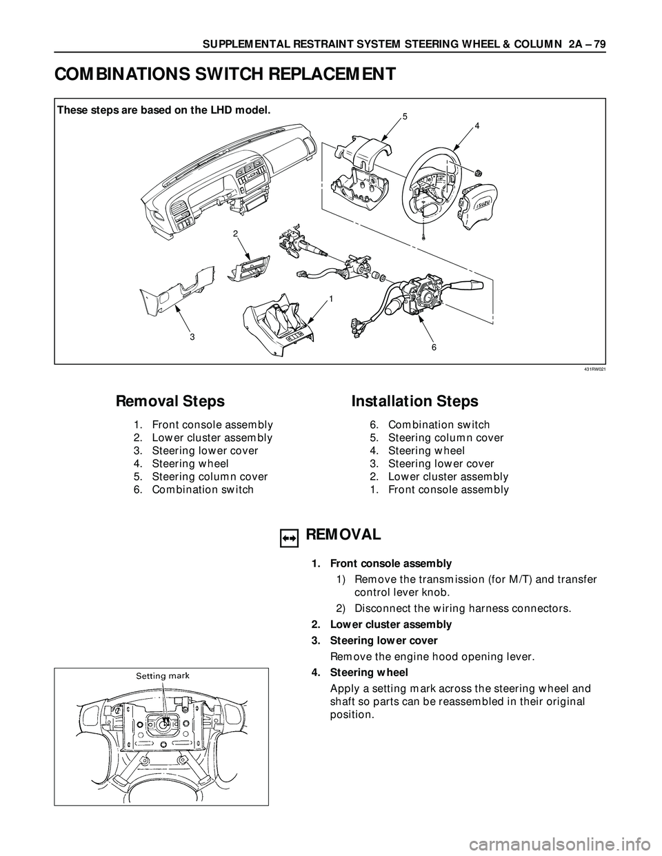
Removal Steps
1. Front console assembly
2. Lower cluster assembly
3. Steering lower cover
4. Steering wheel
5. Steering column cover
6. Combination switch
Installation Steps
6. Combination switch
5. Steering column cover
4. Steering wheel
3. Steering lower cover
2. Lower cluster assembly
1. Front console assembly
REMOVAL
1. Front console assembly
1) Remove the transmission (for M/T) and transfer
control lever knob.
2) Disconnect the wiring harness connectors.
2. Lower cluster assembly
3. Steering lower cover
Remove the engine hood opening lever.
4. Steering wheel
Apply a setting mark across the steering wheel and
shaft so parts can be reassembled in their original
position.
COMBINATIONS SWITCH REPLACEMENT
431RW021
These steps are based on the LHD model.
Page 382 of 3573
2A – 80 SUPPLEMENTAL RESTRAINT SYSTEM STEERING WHEEL & COLUMN
INSTALLATION
6. Combination switch
After installations of combinations switch assembly,
connect the combination switch wiring harness
connector.
5. Steering column cover
4. Steering wheel
Align the setting marks made when removing.
CAUTION:
Never apply force to the setting wheel in direction of the
shaft by using a hammer or other impact tools in an
attempt to remove the steering wheel. The steering shaft
is designed as an energy absorbing unit.
Tighten the steering wheel fixing nut to the specified
torque.
Steering wheel Nut Torque N·m (kg·m/lb·ft)
34 (3.5 / 25)
3. Steering lower cover
Install the engine hood opening lever.
2. Lower cluster assembly
1. Front console assembly
Install the transmission (for M/T) and transfer control
lever knob.
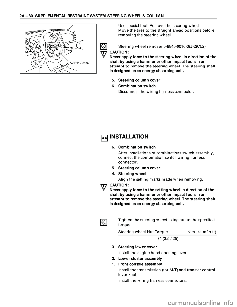
Install the wiring harness connectors. Use special tool. Remove the steering wheel.
Move the tires to the straight ahead positions before
removing the steering wheel.
Steering wheel remover:5-8840-0016-0(J-29752)
CAUTION:
Never apply force to the steering wheel in direction of the
shaft by using a hammer or other impact tools in an
attempt to remove the steering wheel. The steering shaft
is designed as an energy absorbing unit.
5. Steering column cover
6. Combination switch
Disconnect the wiring harness connector.
Page 383 of 3573
SUPPLEMENTAL RESTRAINT SYSTEM STEERING WHEEL & COLUMN 2A – 81
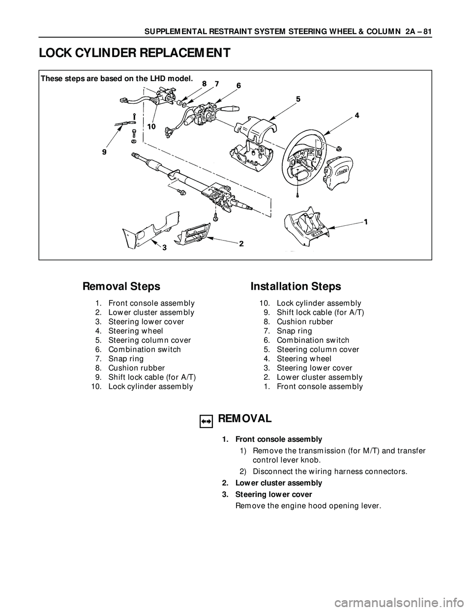
These steps are based on the LHD model.
REMOVAL
1. Front console assembly
1) Remove the transmission (for M/T) and transfer
control lever knob.
2) Disconnect the wiring harness connectors.
2. Lower cluster assembly
3. Steering lower cover
Remove the engine hood opening lever.
LOCK CYLINDER REPLACEMENT
Removal Steps
1. Front console assembly
2. Lower cluster assembly
3. Steering lower cover
4. Steering wheel
5. Steering column cover
6. Combination switch
7. Snap ring
8. Cushion rubber
9. Shift lock cable (for A/T)
10. Lock cylinder assembly
Installation Steps
10. Lock cylinder assembly
9. Shift lock cable (for A/T)
8. Cushion rubber
7. Snap ring
6. Combination switch
5. Steering column cover
4. Steering wheel
3. Steering lower cover
2. Lower cluster assembly
1. Front console assembly