belt ISUZU TROOPER 1998 Service Repair Manual
[x] Cancel search | Manufacturer: ISUZU, Model Year: 1998, Model line: TROOPER, Model: ISUZU TROOPER 1998Pages: 3573, PDF Size: 60.36 MB
Page 3548 of 3573
9J1±61
RESTRAINT CONTROL SYSTEM
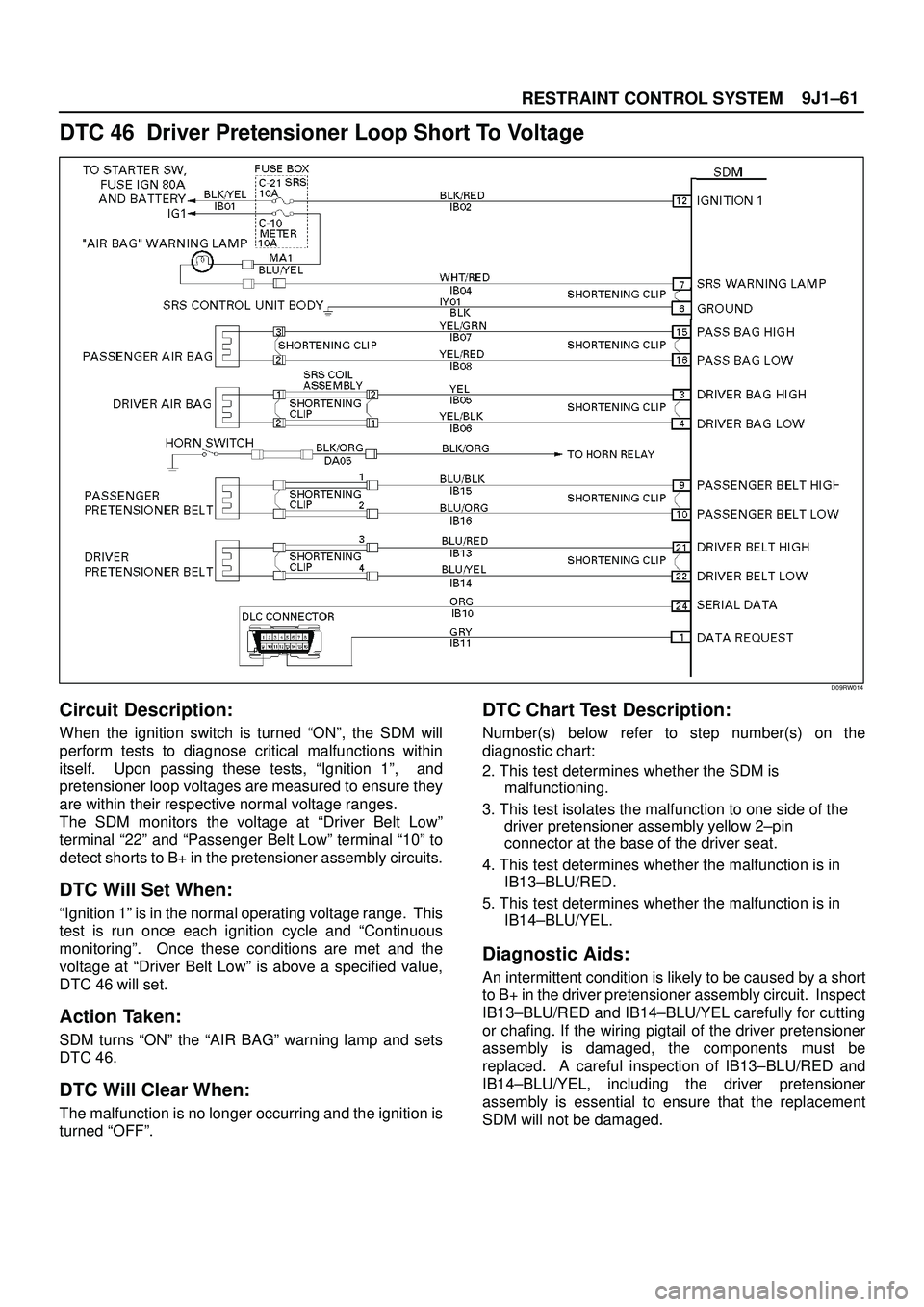
DTC 46 Driver Pretensioner Loop Short To Voltage
D09RW014
Circuit Description:
When the ignition switch is turned ªONº, the SDM will
perform tests to diagnose critical malfunctions within
itself. Upon passing these tests, ªIgnition 1º, and
pretensioner loop voltages are measured to ensure they
are within their respective normal voltage ranges.
The SDM monitors the voltage at ªDriver Belt Lowº
terminal ª22º and ªPassenger Belt Lowº terminal ª10º to
detect shorts to B+ in the pretensioner assembly circuits.
DTC Will Set When:
ªIgnition 1º is in the normal operating voltage range. This
test is run once each ignition cycle and ªContinuous
monitoringº. Once these conditions are met and the
voltage at ªDriver Belt Lowº is above a specified value,
DTC 46 will set.
Action Taken:
SDM turns ªONº the ªAIR BAGº warning lamp and sets
DTC 46.
DTC Will Clear When:
The malfunction is no longer occurring and the ignition is
turned ªOFFº.
DTC Chart Test Description:
Number(s) below refer to step number(s) on the
diagnostic chart:
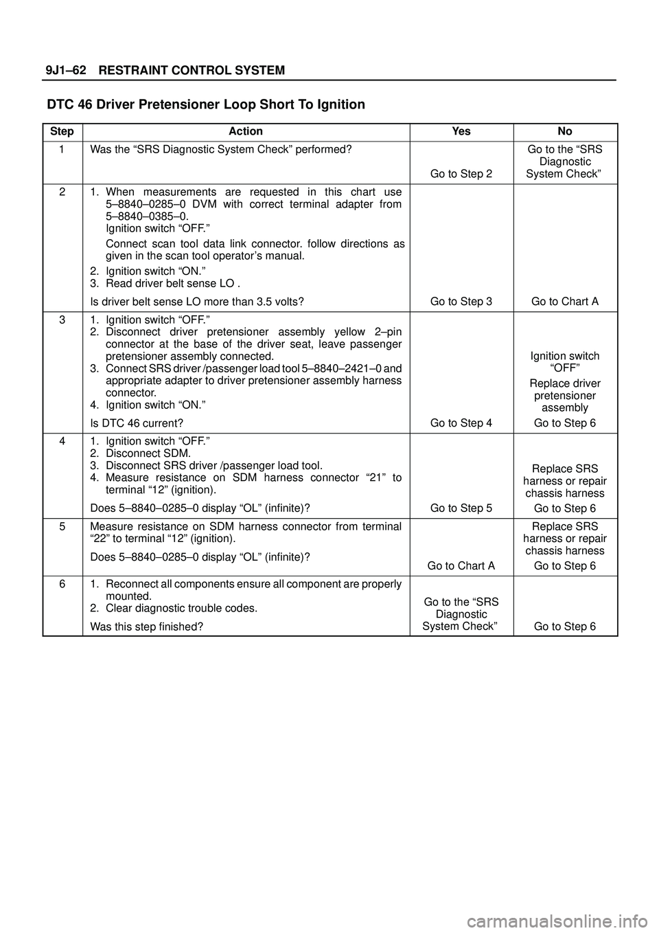
2. This test determines whether the SDM is
malfunctioning.
3. This test isolates the malfunction to one side of the
driver pretensioner assembly yellow 2±pin
connector at the base of the driver seat.
4. This test determines whether the malfunction is in
IB13±BLU/RED.
5. This test determines whether the malfunction is in
IB14±BLU/YEL.
Diagnostic Aids:
An intermittent condition is likely to be caused by a short
to B+ in the driver pretensioner assembly circuit. Inspect
IB13±BLU/RED and IB14±BLU/YEL carefully for cutting
or chafing. If the wiring pigtail of the driver pretensioner
assembly is damaged, the components must be
replaced. A careful inspection of IB13±BLU/RED and
IB14±BLU/YEL, including the driver pretensioner
assembly is essential to ensure that the replacement
SDM will not be damaged.
Page 3549 of 3573
RESTRAINT CONTROL SYSTEM 9J1±62
DTC 46 Driver Pretensioner Loop Short To Ignition
StepActionYe sNo
1Was the ªSRS Diagnostic System Checkº performed?
Go to Step 2
Go to the ªSRS
Diagnostic
System Checkº
21. When measurements are requested in this chart use
5±8840±0285±0 DVM with correct terminal adapter from
5±8840±0385±0.
Ignition switch ªOFF.º
Connect scan tool data link connector. follow directions as
given in the scan tool operator's manual.
2. Ignition switch ªON.º
3. Read driver belt sense LO .
Is driver belt sense LO more than 3.5 volts?
Go to Step 3Go to Chart A
31. Ignition switch ªOFF.º
2. Disconnect driver pretensioner assembly yellow 2±pin
connector at the base of the driver seat, leave passenger
pretensioner assembly connected.
3. Connect SRS driver /passenger load tool 5±8840±2421±0 and
appropriate adapter to driver pretensioner assembly harness
connector.
4. Ignition switch ªON.º
Is DTC 46 current?
Go to Step 4
Ignition switch
ªOFFº
Replace driver
pretensioner
assembly
Go to Step 6
41. Ignition switch ªOFF.º
2. Disconnect SDM.
3. Disconnect SRS driver /passenger load tool.
4. Measure resistance on SDM harness connector ª21º to
terminal ª12º (ignition).
Does 5±8840±0285±0 display ªOLº (infinite)?
Go to Step 5
Replace SRS
harness or repair
chassis harness
Go to Step 6
5Measure resistance on SDM harness connector from terminal
ª22º to terminal ª12º (ignition).
Does 5±8840±0285±0 display ªOLº (infinite)?
Go to Chart A
Replace SRS
harness or repair
chassis harness
Go to Step 6
61. Reconnect all components ensure all component are properly
mounted.
2. Clear diagnostic trouble codes.
Was this step finished?
Go to the ªSRS
Diagnostic
System Checkº
Go to Step 6
Page 3550 of 3573
9J1±63
RESTRAINT CONTROL SYSTEM
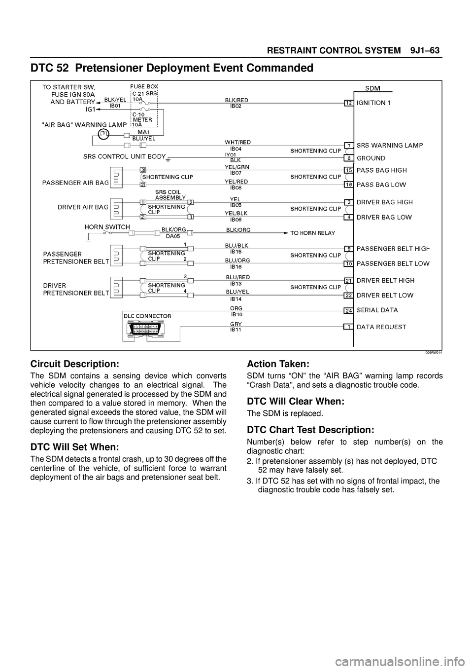
DTC 52 Pretensioner Deployment Event Commanded
D09RW014
Circuit Description:
The SDM contains a sensing device which converts
vehicle velocity changes to an electrical signal. The
electrical signal generated is processed by the SDM and
then compared to a value stored in memory. When the
generated signal exceeds the stored value, the SDM will
cause current to flow through the pretensioner assembly
deploying the pretensioners and causing DTC 52 to set.
DTC Will Set When:
The SDM detects a frontal crash, up to 30 degrees off the
centerline of the vehicle, of sufficient force to warrant
deployment of the air bags and pretensioner seat belt.
Action Taken:
SDM turns ªONº the ªAIR BAGº warning lamp records
ªCrash Dataº, and sets a diagnostic trouble code.
DTC Will Clear When:
The SDM is replaced.
DTC Chart Test Description:
Number(s) below refer to step number(s) on the
diagnostic chart:
2. If pretensioner assembly (s) has not deployed, DTC
52 may have falsely set.
3. If DTC 52 has set with no signs of frontal impact, the
diagnostic trouble code has falsely set.
Page 3570 of 3573
PAGE BACK PAGE NEXT
THIS MALUAL INCLUDES THE FOLLOWING SECTIONS:
SECTION No. CONTRNTS
9A SEAT BELT SYSTEM
9J SUPPLEMENTAL RESTRAINT SYSTEM
9J1 RESTRAINT CONTROL SYSTEM