wheel bolt torque ISUZU TROOPER 1998 Service Service Manual
[x] Cancel search | Manufacturer: ISUZU, Model Year: 1998, Model line: TROOPER, Model: ISUZU TROOPER 1998Pages: 3573, PDF Size: 60.36 MB
Page 1582 of 3573
6A Ð 32 ENGINE MECHANICAL
19 (1.9/14)N·m(kg·m/lb·ft)
5. Timing Gear Case
1) Install the timing gear case to the cylinder body.
NOTE:
Take care not to twist the front oil seal.
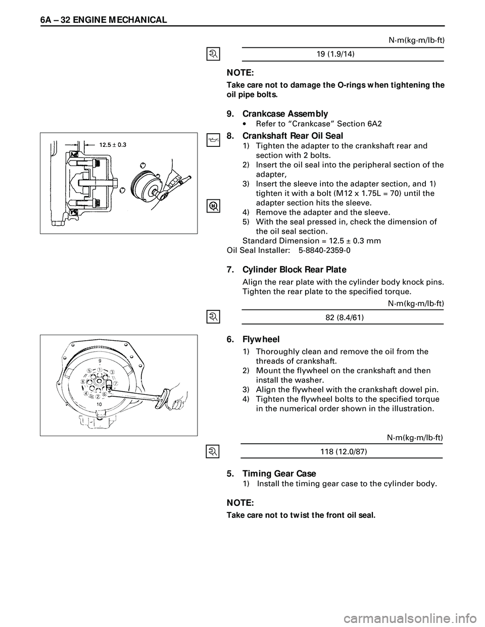
6. Flywheel
1) Thoroughly clean and remove the oil from the
threads of crankshaft.
2) Mount the flywheel on the crankshaft and then
install the washer.
3) Align the flywheel with the crankshaft dowel pin.
4) Tighten the flywheel bolts to the specified torque
in the numerical order shown in the illustration.
82 (8.4/61)N·m(kg·m/lb·ft)
NOTE:
Take care not to damage the O-rings when tightening the
oil pipe bolts.
9. Crankcase Assembly
·Refer to ÒCrankcaseÓ Section 6A2
8. Crankshaft Rear Oil Seal
1) Tighten the adapter to the crankshaft rear and
section with 2 bolts.
2) Insert the oil seal into the peripheral section of the
adapter,
3) Insert the sleeve into the adapter section, and 1)
tighten it with a bolt (M12 x 1.75L = 70) until the
adapter section hits the sleeve.
4) Remove the adapter and the sleeve.
5) With the seal pressed in, check the dimension of
the oil seal section.
Standard Dimension = 12.5 ± 0.3 mm
Oil Seal Installer: 5-8840-2359-0
7. Cylinder Block Rear Plate
Align the rear plate with the cylinder body knock pins.
Tighten the rear plate to the specified torque.
118 (12.0/87)N·m(kg·m/lb·ft)
Page 1600 of 3573
6A Ð 50 ENGINE MECHANICAL
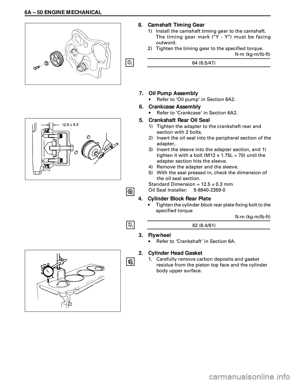
8. Camshaft Timing Gear
1) Install the camshaft timing gear to the camshaft.
The timing gear mark ("Y - Y") must be facing
outword.
2) Tighten the timing gear to the specified torque.
64 (6.5/47)N·m (kg·m/lb·ft)
7. Oil Pump Assembly
·Refer to ÔOil pumpÕ in Section 6A2.
6. Crankcase Assembly
·Refer to ÔCrankcaseÕ in Section 6A2.
5. Crankshaft Rear Oil Seal
1) Tighten the adapter to the crankshaft rear and
section with 2 bolts.
2) Insert the oil seal into the peripheral section of the
adapter,
3) Insert the sleeve into the adapter section, and 1)
tighten it with a bolt (M12 x 1.75L = 70) until the
adapter section hits the sleeve.
4) Remove the adapter and the sleeve.
5) With the seal pressed in, check the dimension of
the oil seal section.
Standard Dimension = 12.5 ± 0.3 mm
Oil Seal Installer: 5-8840-2359-0
4. Cylinder Block Rear Plate
·Tighten the cylinder block rear plate fixing bolt to the
specified torque
82 (8.4/61)N·m (kg·m/lb·ft)
3. Flywheel
·Refer to ÔCrankshaftÕ in Section 6A.
2. Cylinder Head Gasket
1. Carefully remove carbon deposits and gasket
residue from the piston top face and the cylinder
body upper surface.
Page 1616 of 3573
6A2Ð 14 4JG2-NA/4JG2-TURBO ENGINE
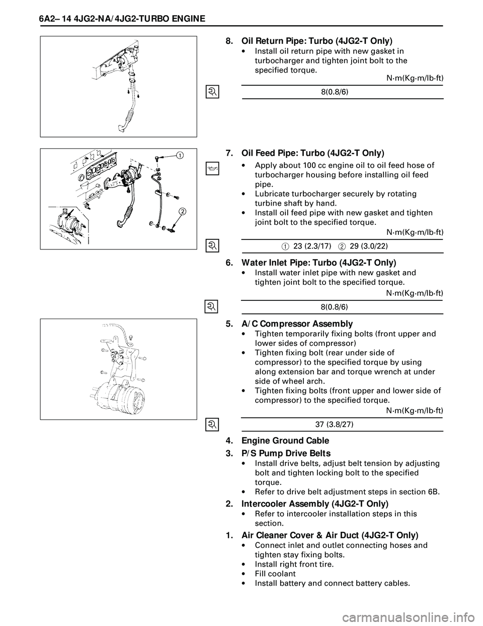
8. Oil Return Pipe: Turbo (4JG2-T Only)
·Install oil return pipe with new gasket in
turbocharger and tighten joint bolt to the
specified torque.
7. Oil Feed Pipe: Turbo (4JG2-T Only)
·Apply about 100 cc engine oil to oil feed hose of
turbocharger housing before installing oil feed
pipe.
·Lubricate turbocharger securely by rotating
turbine shaft by hand.
·Install oil feed pipe with new gasket and tighten
joint bolt to the specified torque.
6. Water Inlet Pipe: Turbo (4JG2-T Only)
·Install water inlet pipe with new gasket and
tighten joint bolt to the specified torque.
4. Engine Ground Cable
3. P/S Pump Drive Belts
·Install drive belts, adjust belt tension by adjusting
bolt and tighten locking bolt to the specified
torque.
·Refer to drive belt adjustment steps in section 6B.
2. Intercooler Assembly (4JG2-T Only)
·Refer to intercooler installation steps in this
section.
1. Air Cleaner Cover & Air Duct (4JG2-T Only)
·Connect inlet and outlet connecting hoses and
tighten stay fixing bolts.
·Install right front tire.
·Fill coolant
·Install battery and connect battery cables.
5. A/C Compressor Assembly
·Tighten temporarily fixing bolts (front upper and
lower sides of compressor)
·Tighten fixing bolt (rear under side of
compressor) to the specified torque by using
along extension bar and torque wrench at under
side of wheel arch.
·Tighten fixing bolts (front upper and lower side of
compressor) to the specified torque.
8(0.8/6)N·m(Kg·m/lb·ft)
123 (2.3/17)229 (3.0/22)N·m(Kg·m/lb·ft)
8(0.8/6)N·m(Kg·m/lb·ft)
37 (3.8/27)N·m(Kg·m/lb·ft)
Page 1622 of 3573
6A2 Ð 20 4JG2-NA/4JG2-TURBO ENGINE
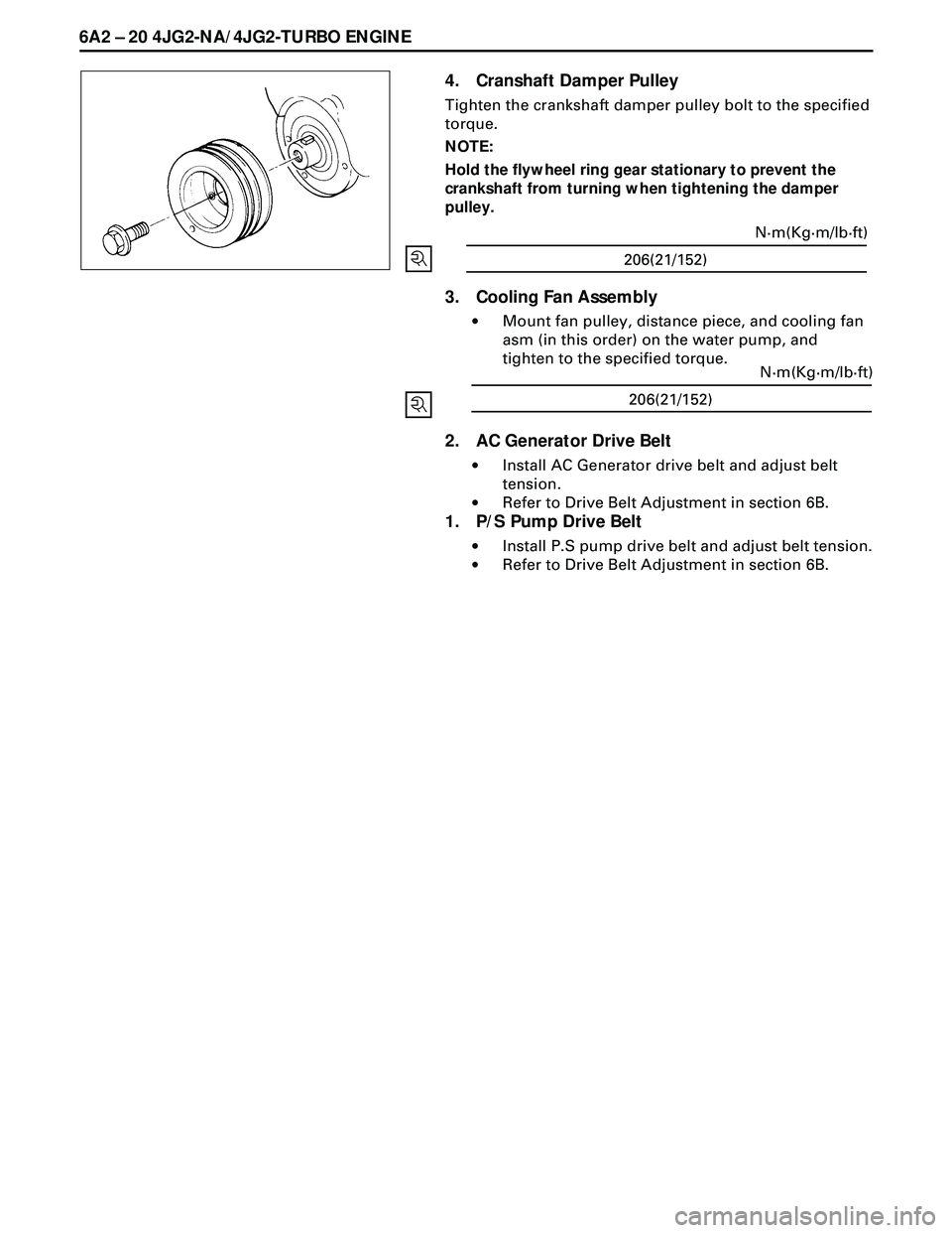
4. Cranshaft Damper Pulley
Tighten the crankshaft damper pulley bolt to the specified
torque.
NOTE:
Hold the flywheel ring gear stationary to prevent the
crankshaft from turning when tightening the damper
pulley.
3. Cooling Fan Assembly
·Mount fan pulley, distance piece, and cooling fan
asm (in this order) on the water pump, and
tighten to the specified torque.
2. AC Generator Drive Belt
·Install AC Generator drive belt and adjust belt
tension.
·Refer to Drive Belt Adjustment in section 6B.
1. P/S Pump Drive Belt
·Install P.S pump drive belt and adjust belt tension.
·Refer to Drive Belt Adjustment in section 6B.
206(21/152)N·m(Kg·m/lb·ft)
206(21/152)N·m(Kg·m/lb·ft)
Page 1632 of 3573
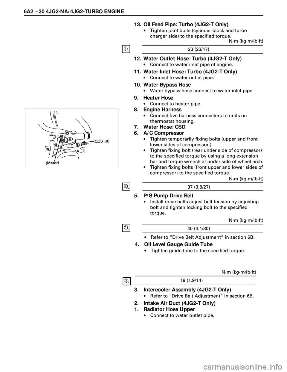
6A2 Ð 30 4JG2-NA/4JG2-TURBO ENGINE
13. Oil Feed Pipe: Turbo (4JG2-T Only)
·Tighten joint bolts (cylinder block and turbo
charger side) to the specified torque.
12. Water Outlet Hose: Turbo (4JG2-T Only)
·Connect to water inlet pipe of engine.
11. Water Inlet Hose: Turbo (4JG2-T Only)
·Connect to water outlet pipe.
10. Water Bypass Hose
·Water bypass hose connect to water inlet pipe.
9. Heater Hose
·Connect to heater pipe.
8. Engine Harness
·Connect five harness connecters to units on
thermostat housing.
7. Water Hose: CSD
6. A/C Compressor
·Tighten temporarily fixing bolts (upper and front
lower sides of compressor.)
·Tighten fixing bolt (rear under side of compressor)
to the specified torque by using a long extension
bar and torque wrench at under side of wheel arch.
·Tighten fixing bolts (front upper and lower sides of
compressor) to the specified torque.
5. P/S Pump Drive Belt
·Install drive belts adjust belt tension by adjusting
bolt and tighten locking bolt to the specified
torque.
·Refer to ÒDrive Belt AdjustmentÓ in section 6B.
4. Oil Level Gauge Guide Tube
·Tighten guide tube to the specified torque.
23 (23/17)N·m (kg·m/lb·ft)
37 (3.8/27)N·m (kg·m/lb·ft)
40 (4.1/30)N·m (kg·m/lb·ft)
19 (1.9/14)N·m (kg·m/lb·ft)
3. Intercooler Assembly (4JG2-T Only)
·Refer to ÒDrive Belt AdjustmentÓ in section 6B.
2. Intake Air Duct (4JG2-T Only)
1. Radiator Hose Upper
·Connect to water outlet pipe.
Page 1642 of 3573
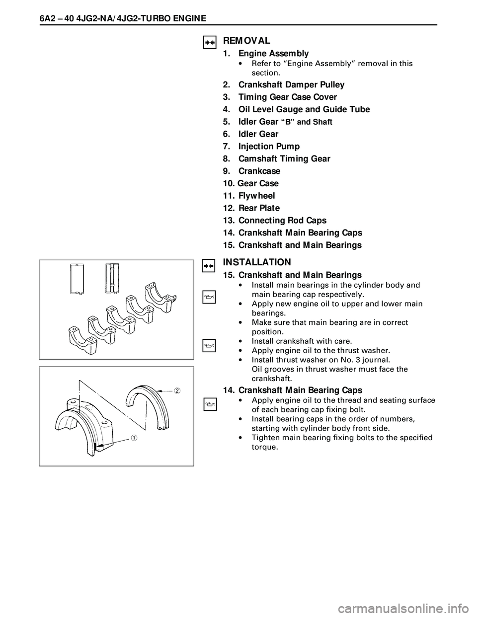
6A2 Ð 40 4JG2-NA/4JG2-TURBO ENGINE
REMOVAL
1. Engine Assembly
·Refer to ÒEngine AssemblyÓ removal in this
section.
2. Crankshaft Damper Pulley
3. Timing Gear Case Cover
4. Oil Level Gauge and Guide Tube
5. Idler Gear
ÒBÓ and Shaft
6. Idler Gear
7. Injection Pump
8. Camshaft Timing Gear
9. Crankcase
10. Gear Case
11. Flywheel
12. Rear Plate
13. Connecting Rod Caps
14. Crankshaft Main Bearing Caps
15. Crankshaft and Main Bearings
INSTALLATION
15. Crankshaft and Main Bearings
·Install main bearings in the cylinder body and
main bearing cap respectively.
·Apply new engine oil to upper and lower main
bearings.
·Make sure that main bearing are in correct
position.
·Install crankshaft with care.
·Apply engine oil to the thrust washer.
·Install thrust washer on No. 3 journal.
Oil grooves in thrust washer must face the
crankshaft.
14. Crankshaft Main Bearing Caps
·Apply engine oil to the thread and seating surface
of each bearing cap fixing bolt.
·Install bearing caps in the order of numbers,
starting with cylinder body front side.
·Tighten main bearing fixing bolts to the specified
torque.
Page 1643 of 3573
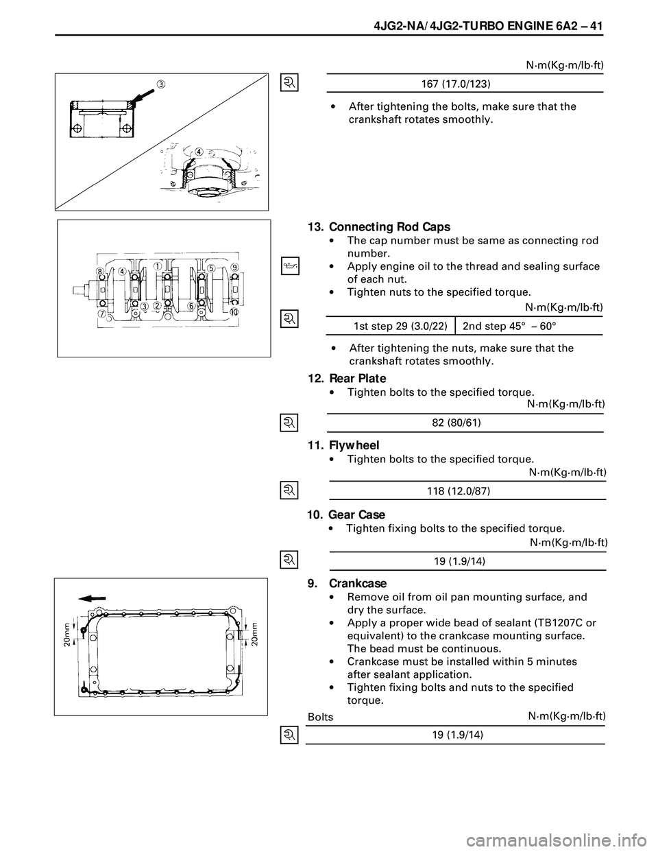
4JG2-NA/4JG2-TURBO ENGINE 6A2 Ð 41
19 (1.9/14)N·m(Kg·m/lb·ft)
·After tightening the bolts, make sure that the
crankshaft rotates smoothly.
167 (17.0/123)N·m(Kg·m/lb·ft)
13. Connecting Rod Caps
·The cap number must be same as connecting rod
number.
·Apply engine oil to the thread and sealing surface
of each nut.
·Tighten nuts to the specified torque.
·After tightening the nuts, make sure that the
crankshaft rotates smoothly.
12. Rear Plate
·Tighten bolts to the specified torque.
82 (80/61)N·m(Kg·m/lb·ft)
11. Flywheel
·Tighten bolts to the specified torque.
118 (12.0/87)N·m(Kg·m/lb·ft)
10. Gear Case
·Tighten fixing bolts to the specified torque.
19 (1.9/14)N·m(Kg·m/lb·ft)
9. Crankcase
·Remove oil from oil pan mounting surface, and
dry the surface.
·Apply a proper wide bead of sealant (TB1207C or
equivalent) to the crankcase mounting surface.
The bead must be continuous.
·Crankcase must be installed within 5 minutes
after sealant application.
·Tighten fixing bolts and nuts to the specified
torque.
Bolts
1st step 29 (3.0/22) 2nd step 45° – 60°N·m(Kg·m/lb·ft)
Page 1646 of 3573
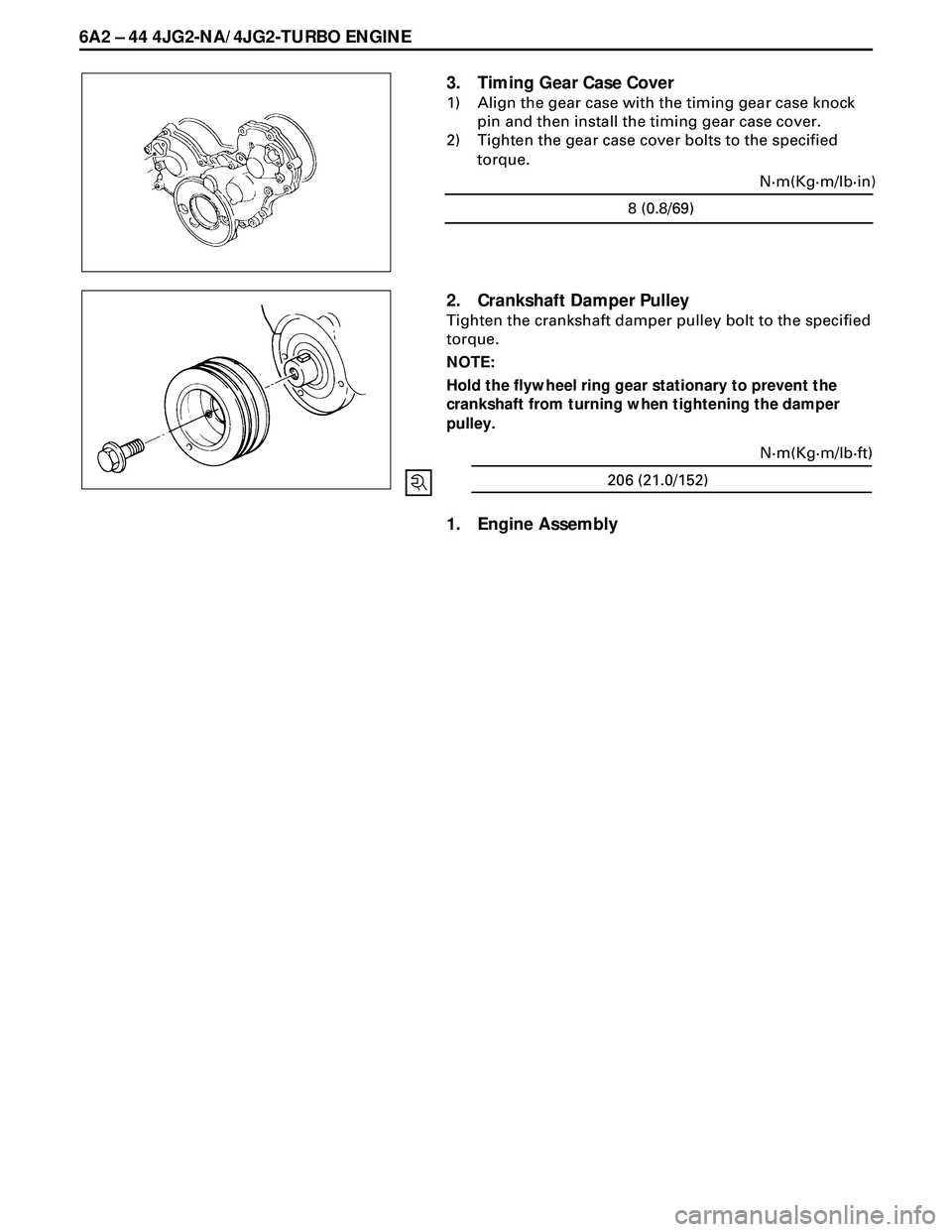
6A2 Ð 44 4JG2-NA/4JG2-TURBO ENGINE
3. Timing Gear Case Cover
1) Align the gear case with the timing gear case knock
pin and then install the timing gear case cover.
2) Tighten the gear case cover bolts to the specified
torque.
2. Crankshaft Damper Pulley
Tighten the crankshaft damper pulley bolt to the specified
torque.
NOTE:
Hold the flywheel ring gear stationary to prevent the
crankshaft from turning when tightening the damper
pulley.
1. Engine Assembly
8 (0.8/69)N·m(Kg·m/lb·in)
206 (21.0/152)N·m(Kg·m/lb·ft)
Page 1649 of 3573
4JG2-NA/4JG2-TURBO ENGINE 6A2 Ð 47
2. Flywheel
·Tighten bolts to the specified torque.
118 (12.0/87)N·m(Kg·m/lb·ft)
1. Transmission Assembly
·Refer to ÒTransmissionÓ installation in section 7.
Page 1652 of 3573
6A2 Ð 50 4JG2-NA/4JG2-TURBO ENGINE
18. Vacuum Hose : Vacuum Tank
·Disconnect vacuum hose from vacuum pump
side.
19. Glow Plug Harness
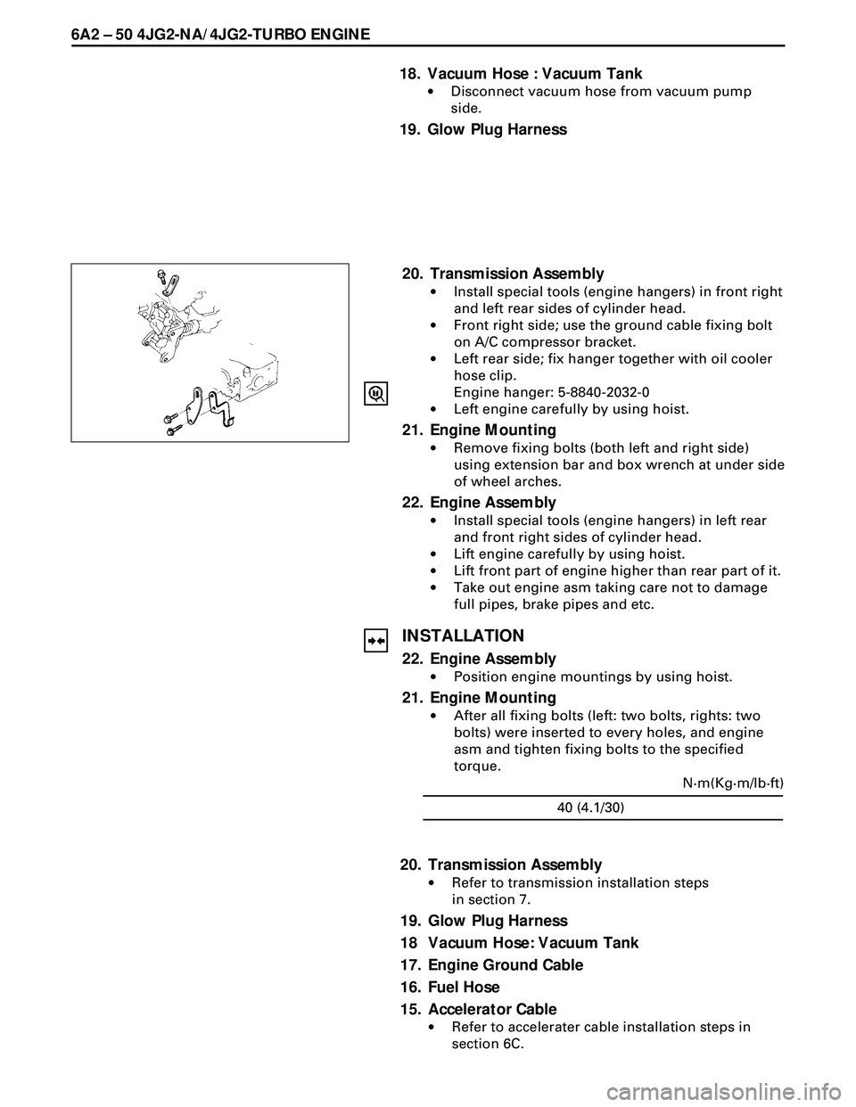
20. Transmission Assembly
·Install special tools (engine hangers) in front right
and left rear sides of cylinder head.
·Front right side; use the ground cable fixing bolt
on A/C compressor bracket.
·Left rear side; fix hanger together with oil cooler
hose clip.
Engine hanger: 5-8840-2032-0
·Left engine carefully by using hoist.
21. Engine Mounting
·Remove fixing bolts (both left and right side)
using extension bar and box wrench at under side
of wheel arches.
22. Engine Assembly
·Install special tools (engine hangers) in left rear
and front right sides of cylinder head.
·Lift engine carefully by using hoist.
·Lift front part of engine higher than rear part of it.
·Take out engine asm taking care not to damage
full pipes, brake pipes and etc.
INSTALLATION
22. Engine Assembly
·Position engine mountings by using hoist.
21. Engine Mounting
·After all fixing bolts (left: two bolts, rights: two
bolts) were inserted to every holes, and engine
asm and tighten fixing bolts to the specified
torque.
40 (4.1/30)N·m(Kg·m/lb·ft)
20. Transmission Assembly
·Refer to transmission installation steps
in section 7.
19. Glow Plug Harness
18 Vacuum Hose: Vacuum Tank
17. Engine Ground Cable
16. Fuel Hose
15. Accelerator Cable
·Refer to accelerater cable installation steps in
section 6C.