brake rotor ISUZU TROOPER 1998 Service Repair Manual
[x] Cancel search | Manufacturer: ISUZU, Model Year: 1998, Model line: TROOPER, Model: ISUZU TROOPER 1998Pages: 3573, PDF Size: 60.36 MB
Page 814 of 3573
5A±4
BRAKE CONTROL SYSTEM
normal braking when a malfunction has occurred in the
ABS.
The EHCU has a self-diagnosing function which can
indicate faulty circuits during diagnosis.
The EHCU is mounted on the engine compartment front
right side. It consists of a Motor, Plunger Pump, Solenoid
Valves and Check Valve.
On the outside, the relay box containing a motor relay and
a valve relay is installed.
Solenoid Valves: Reduces or holds the caliper fluid
pressure for each front disc brake or both rear disc brakes
according to the signal sent from the EHCU.
Reservoir: Temporarily holds the brake fluid that returns
from the front and rear disc brake caliper so that pressure
of front disc brake caliper can be reduced smoothly.
Plunger Pump: Feeds the brake fluid held in the reservoir
to the master cylinder.
Motor: Drives the pump according to the signal from
EHCU.
Check Valve: Controls the brake fluid flow.
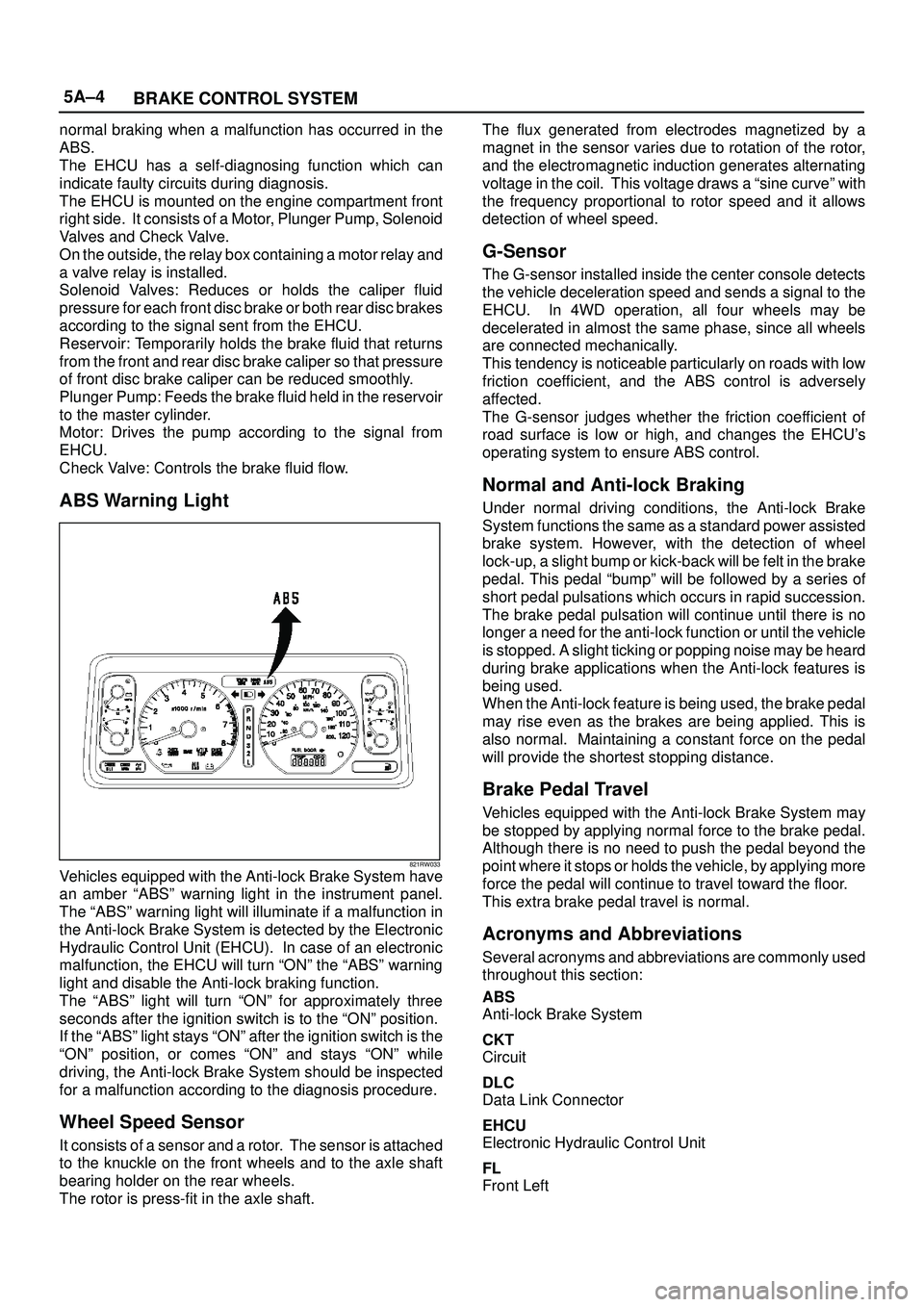
ABS Warning Light
821RW033Vehicles equipped with the Anti-lock Brake System have
an amber ªABSº warning light in the instrument panel.
The ªABSº warning light will illuminate if a malfunction in
the Anti-lock Brake System is detected by the Electronic
Hydraulic Control Unit (EHCU). In case of an electronic
malfunction, the EHCU will turn ªONº the ªABSº warning
light and disable the Anti-lock braking function.
The ªABSº light will turn ªONº for approximately three
seconds after the ignition switch is to the ªONº position.
If the ªABSº light stays ªONº after the ignition switch is the
ªONº position, or comes ªONº and stays ªONº while
driving, the Anti-lock Brake System should be inspected
for a malfunction according to the diagnosis procedure.
Wheel Speed Sensor
It consists of a sensor and a rotor. The sensor is attached
to the knuckle on the front wheels and to the axle shaft
bearing holder on the rear wheels.
The rotor is press-fit in the axle shaft.The flux generated from electrodes magnetized by a
magnet in the sensor varies due to rotation of the rotor,
and the electromagnetic induction generates alternating
voltage in the coil. This voltage draws a ªsine curveº with
the frequency proportional to rotor speed and it allows
detection of wheel speed.
G-Sensor
The G-sensor installed inside the center console detects
the vehicle deceleration speed and sends a signal to the
EHCU. In 4WD operation, all four wheels may be
decelerated in almost the same phase, since all wheels
are connected mechanically.
This tendency is noticeable particularly on roads with low
friction coefficient, and the ABS control is adversely
affected.
The G-sensor judges whether the friction coefficient of
road surface is low or high, and changes the EHCU's
operating system to ensure ABS control.
Normal and Anti-lock Braking
Under normal driving conditions, the Anti-lock Brake
System functions the same as a standard power assisted
brake system. However, with the detection of wheel
lock-up, a slight bump or kick-back will be felt in the brake
pedal. This pedal ªbumpº will be followed by a series of
short pedal pulsations which occurs in rapid succession.
The brake pedal pulsation will continue until there is no
longer a need for the anti-lock function or until the vehicle
is stopped. A slight ticking or popping noise may be heard
during brake applications when the Anti-lock features is
being used.
When the Anti-lock feature is being used, the brake pedal
may rise even as the brakes are being applied. This is
also normal. Maintaining a constant force on the pedal
will provide the shortest stopping distance.
Brake Pedal Travel
Vehicles equipped with the Anti-lock Brake System may
be stopped by applying normal force to the brake pedal.
Although there is no need to push the pedal beyond the
point where it stops or holds the vehicle, by applying more
force the pedal will continue to travel toward the floor.
This extra brake pedal travel is normal.
Acronyms and Abbreviations
Several acronyms and abbreviations are commonly used
throughout this section:
ABS
Anti-lock Brake System
CKT
Circuit
DLC
Data Link Connector
EHCU
Electronic Hydraulic Control Unit
FL
Front Left
Page 817 of 3573
5A±7 BRAKE CONTROL SYSTEM
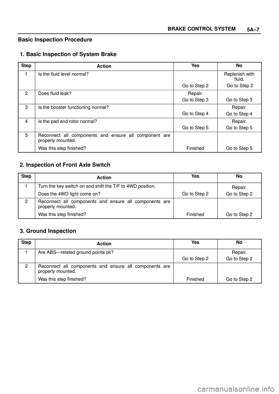
Basic Inspection Procedure
1. Basic Inspection of System Brake
StepActionYe sNo
1Is the fluid level normal?
Go to Step 2
Replenish with
fluid.
Go to Step 2
2Does fluid leak?Repair.
Go to Step 3
Go to Step 3
3Is the booster functioning normal?
Go to Step 4
Repair.
Go to Step 4
4Is the pad and rotor normal?
Go to Step 5
Repair.
Go to Step 5
5Reconnect all components and ensure all component are
properly mounted.
Was this step finished?
FinishedGo to Step 5
2. Inspection of Front Axle Switch
StepActionYe sNo
1Turn the key switch on and shift the T/F to 4WD position.
Does the 4WD light come on?
Go to Step 2
Repair.
Go to Step 2
2Reconnect all components and ensure all components are
properly mounted.
Was this step finished?
FinishedGo to Step 2
3. Ground Inspection
StepActionYe sNo
1Are ABSÐrelated ground points ok?
Go to Step 2
Repair.
Go to Step 2
2Reconnect all components and ensure all components are
properly mounted.
Was this step finished?
FinishedGo to Step 2
Page 862 of 3573

5A±52
BRAKE CONTROL SYSTEM
Chart B-20 FL Speed Sensor Short Circuit (DTC 61)
StepActionYe sNo
11. Turn the key off.
2. Disconnect EHCU connector
3. Measure the FL speed sensor resistance between EHCU
connector terminals 20 and 21.
Is the resistance between 1.3k and 1.9k ohms?
Go to Step 2Go to Step 3
2Is there play in the sensor/sensor rotor?
Go to Step 4
Repair.
Go to Step 6
3Measure the FL speed sensor resistance at the sensor connector.
Is the resistance between 1.3k and 1.9k ohms?Repair harness
abnormality
between sensors
and EHCU.
Go to Step 6
Replace sensor.
Go to Step 6
4Damage and powdered iron sticking to sensor/sensor ring?
Go to Step 5
Repair.
Go to Step 6
5Is sensor output normal? (Chart C-1-1 or TC-1)Check for faults
in harness
between speed
sensor and
EHCU.
Fault found:
repair, and
perform system
self-check.
No fault found:
replace EHCU.
Go to Step 6
Replace sensor.
Go to Step 6
61. Reconnect all components and ensure all components are
properly mounted.
2. Clear diagnostic trouble code.
Was this step finished?
Repeat the ªBasic
diagnostic flow
chart.º
Go to Step 6
NOTE: Even after repairing the faulty part the warning
light (W/L) does not go out if the vehicle is at a stop. Turn
the ignition switch to the ON position and drive the vehicle
at 12 km/h or higher to make sure that the warning light
goes out.
Page 863 of 3573

5A±53 BRAKE CONTROL SYSTEM
Chart B-21 FR Speed Sensor Short Circuit (DTC 62)
StepActionYe sNo
11. Turn the key off.
2. Disconnect EHCU connector.
3. Measure the FR speed sensor resistance between EHCU
connector terminals 4 and 5.
Is the resistance between 1.3k and 1.9k ohms?
Go to Step 2Go to Step 3
2Is there play in the sensor/sensor rotor?
Go to Step 4
Repair.
Go to Step 6
3Measure the FR speed sensor resistance at the sensor
connector.
Is the resistance between 1.3k and 1.9k ohms?Repair harness
abnormality
between sensors
and EHCU.
Go to Step 6
Replace sensor.
Go to Step 6
4Damage and powdered iron sticking to sensor/sensor ring?
Go to Step 5
Repair.
Go to Step 6
5Is sensor output normal? (Chart C-1-2 or TC-1)Check for faults
in harness
between speed
sensor and
EHCU.
Fault found:
repair, and
perform system
self-check.
No fault found:
replace EHCU.
Go to Step 6
Replace sensor.
Go to Step 6
61. Reconnect all components and ensure all components are
properly mounted.
2. Clear diagnostic trouble code.
Was this step finished?
Repeat ªBasic
diagnostic flow
chart.º
Go to Step 6
NOTE: Even after repairing the faulty part the warning
light (W/L) does not go out if the vehicle is at a stop. Turn
the ignition switch to the ON position and drive the vehicle
at 12 km/h or higher to make sure that the warning light
goes out.
Page 864 of 3573

5A±54
BRAKE CONTROL SYSTEM
Chart B-22 RL Speed Sensor Short Circuit (DTC 63)
StepActionYe sNo
11. Turn the key off.
2. Disconnect EHCU connector
3. Measure the RL speed sensor resistance between EHCU
connector terminals 22 and 23.
Is the resistance between 1.3k and 1.9k ohms?
Go to Step 2Go to Step 3
2Is there play in the sensor/sensor rotor?
Go to Step 4
Repair.
Go to Step 6
3Measure the RL speed sensor resistance at the sensor
connector.
Is the resistance between 1.3k and 1.9k ohms?Repair harness
abnormality
between sensors
and EHCU.
Go to Step 6
Replace sensor.
Go to Step 6
4Damage and powdered iron sticking to sensor/sensor ring?
Go to Step 5
Repair.
Go to Step 6
5Is sensor output normal? (Chart C-1-3 or TC-1)?Check for faults
in harness
between speed
sensor and
EHCU.
Fault found:
repair, and
perform system
self-check.
No fault found:
replace EHCU.
Go to Step 6
Replace sensor.
Go to Step 6
61. Reconnect all components and ensure all components are
properly mounted.
2. Clear diagnostic trouble code.
Was this step finished?
Repeat the ªBasic
diagnostic flow
chart.º
Go to Step 6
NOTE: Even after repairing the faulty part the warning
light (W/L) does not go out if the vehicle is at a stop. Turn
the ignition switch to the ON position and drive the vehicle
at 12 km/h or higher to make sure that the warning light
goes out.
Page 865 of 3573

5A±55 BRAKE CONTROL SYSTEM
Chart B-23 RR Speed Sensor Short Circuit (DTC 64)
StepActionYe sNo
11. Turn the key off.
2. Disconnect EHCU connector.
3. Measure the RR speed sensor resistance between EHCU
connector terminals 2 and 3.
Is the resistance between 1.3k and 1.9k ohms?
Go to Step 2Go to Step 3
2Is there play in the sensor/sensor rotor?
Go to Step 4
Repair.
Go to Step 6
3Measure the RR speed sensor resistance at the sensor
connector.
Is the resistance between 1.3k and 1.9k ohms?Repair harness
abnormality
between sensors
and EHCU.
Go to Step 6
Replace sensor.
Go to Step 6
4Damage and powdered iron sticking to sensor/sensor ring?
Go to Step 5
Repair.
Go to Step 6
5Is sensor output normal? (Chart C-1-4 or TC-1)Check for faults
in harness
between speed
sensor and
EHCU.
Fault found:
repair, and
perform system
self-check.
No fault found:
replace EHCU.
Go to Step 6
Replace sensor.
Go to Step 6
61. Reconnect all components and ensure all components are
properly mounted.
2. Clear diagnostic trouble code.
Was this step finished?
Repeat ªBasic
diagnostic flow
chart.º
Go to Step 6
NOTE: Even after repairing the faulty part the warning
light (W/L) does not go out if the vehicle is at a stop. Turn
the ignition switch to the ON position and drive the vehicle
at 12 km/h or higher to make sure that the warning light
goes out.
Page 869 of 3573

5A±59 BRAKE CONTROL SYSTEM
Chart C-1-4 RR Sensor Output Inspection Procedure
StepActionYe sNo
11. Turn the key off.
2. Disconnect EHCU connector.
3. Jack up the vehicle with all four wheels off the ground.
Measure the AC voltage between EHCU connector terminals
while turning RR wheel at a speed of 1 RPS:
Is voltage between EHCU connector terminals 2 and 3 under 200
mV?
Go to Step 2
Ok.
Go to Step 3
21. Disconnect the wheel speed sensor.
2. Measure resistance between the wheel speed sensor
connector terminals 1 and 2.
Is resistance between connector (F-2) terminals 1 and 2 within
1.3k - 1.9k ohms?Connector is
faulty, or open or
short circuit of
harness between
wheel speed
sensor connector
and EHCU.
Inspect and
correct the
connector or
harness
Go to Step 3
Wheel speed
sensor is faulty.
Replace the
wheel speed
sensor.
Go to Step 3
3Reconnect all components and ensure all components are
properly mounted.
Was this step finished?Repeat the ªBasic
diagnostic flow
chart.º
Go to Step 3
Chart TC-1 Sensor Output Inspection Procedure (Use TECH 2)
StepActionYe sNo
11. Connect TECH 2.
2. While driving the vehicle, check the wheel speed of each
sensor by Data List.
Is the vehicle speed value is normal?
Go to Step 6Go to Step 2
2Check the sensor harness for suspected disconnection (Check
while shaking harness/connector).
Is the sensor harness connection normal?Replace speed
sensor.
Go to Step 3
Repair.
Go to Step 6
3While driving the vehicle, check the wheel speed of each sensor
by Data List.
Is the vehicle speed value is normal?
Go to Step 6Go to Step 4
4Check the sensor rotor.
Is the sensor rotor normal?
Go to Step 6
Replace sensor
rotor.
Go to Step 5
5While driving the vehicle, check the wheel speed of each sensor
by Data List.
Is the vehicle speed value is normal?
Go to Step 6
Repair harness or
connector
between EHCU
and speed
sensor.
Go to Step 6
6Reconnect all components, ensure all components are properly
mounted.
Was this step finished?Repeat the ªBasic
diagnostic flow
chart.º
Go to Step 6
Page 883 of 3573
POWER ASSISTED BRAKE SYSTEM 5C – 5
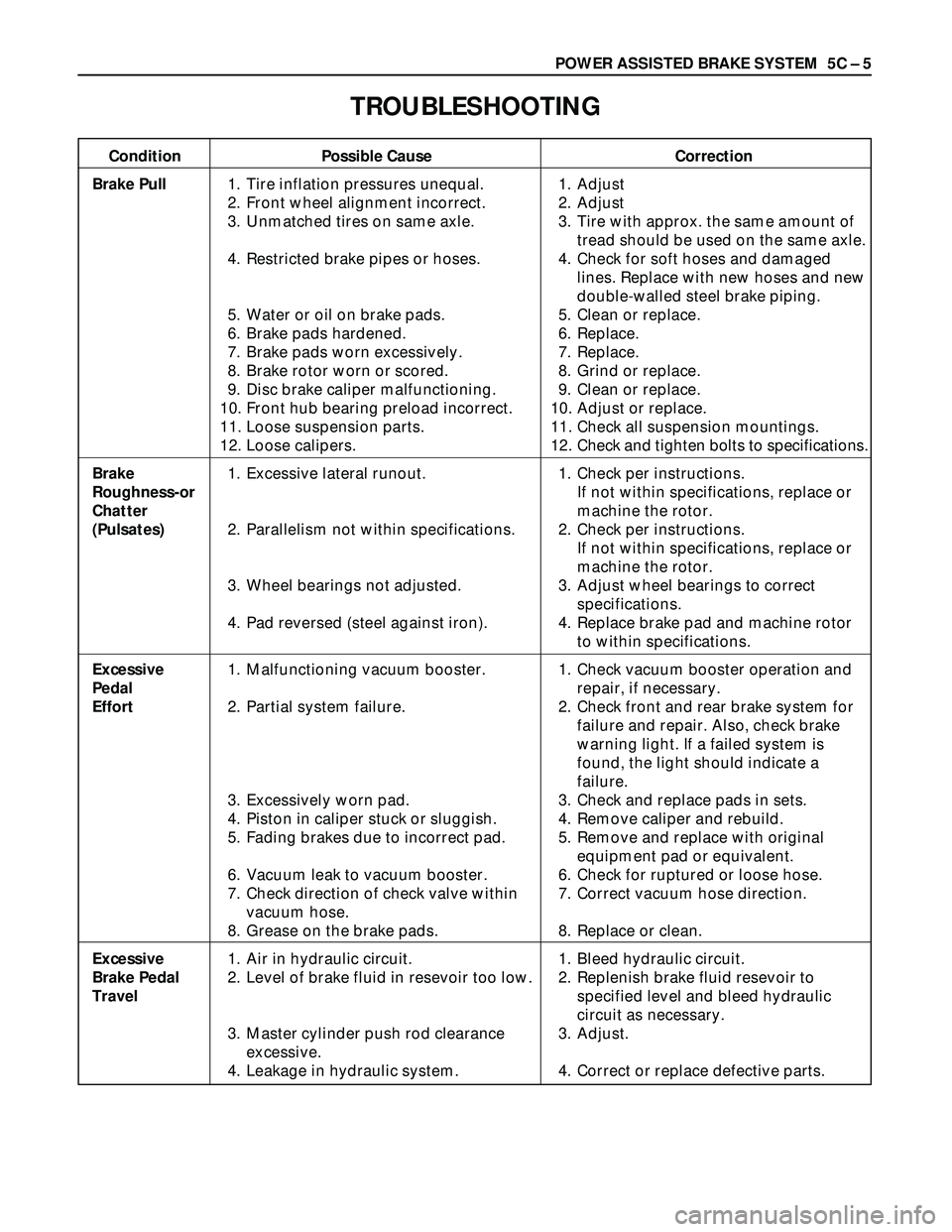
TROUBLESHOOTING
Condition Possible Cause Correction
Brake Pull1. Tire inflation pressures unequal. 1. Adjust
2. Front wheel alignment incorrect. 2. Adjust
3. Unmatched tires on same axle. 3. Tire with approx. the same amount of
tread should be used on the same axle.
4. Restricted brake pipes or hoses. 4. Check for soft hoses and damaged
lines. Replace with new hoses and new
double-walled steel brake piping.
5. Water or oil on brake pads. 5. Clean or replace.
6. Brake pads hardened. 6. Replace.
7. Brake pads worn excessively. 7. Replace.
8. Brake rotor worn or scored. 8. Grind or replace.
9. Disc brake caliper malfunctioning. 9. Clean or replace.
10. Front hub bearing preload incorrect. 10. Adjust or replace.
11. Loose suspension parts. 11. Check all suspension mountings.
12. Loose calipers. 12. Check and tighten bolts to specifications.
Brake 1. Excessive lateral runout. 1. Check per instructions.
Roughness-orIf not within specifications, replace or
Chattermachine the rotor.
(Pulsates)2. Parallelism not within specifications. 2. Check per instructions.
If not within specifications, replace or
machine the rotor.
3. Wheel bearings not adjusted. 3. Adjust wheel bearings to correct
specifications.
4. Pad reversed (steel against iron). 4. Replace brake pad and machine rotor
to within specifications.
Excessive 1. Malfunctioning vacuum booster. 1. Check vacuum booster operation and
Pedal repair, if necessary.
Effort2. Partial system failure. 2. Check front and rear brake system for
failure and repair. Also, check brake
warning light. If a failed system is
found, the light should indicate a
failure.
3. Excessively worn pad. 3. Check and replace pads in sets.
4. Piston in caliper stuck or sluggish. 4. Remove caliper and rebuild.
5. Fading brakes due to incorrect pad. 5. Remove and replace with original
equipment pad or equivalent.
6. Vacuum leak to vacuum booster. 6. Check for ruptured or loose hose.
7. Check direction of check valve within 7. Correct vacuum hose direction.
vacuum hose.
8. Grease on the brake pads. 8. Replace or clean.
Excessive 1. Air in hydraulic circuit. 1. Bleed hydraulic circuit.
Brake Pedal 2. Level of brake fluid in resevoir too low. 2. Replenish brake fluid resevoir to
Travelspecified level and bleed hydraulic
circuit as necessary.
3. Master cylinder push rod clearance 3. Adjust.
excessive.
4. Leakage in hydraulic system. 4. Correct or replace defective parts.
Page 884 of 3573
5C – 6 POWER ASSISTED BRAKE SYSTEM
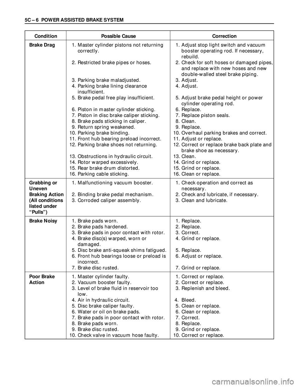
Condition Possible Cause Correction
Brake Drag1. Master cylinder pistons not returning 1. Adjust stop light switch and vacuum
correctly. booster operating rod. If necessary,
rebuild.
2. Restricted brake pipes or hoses. 2. Check for soft hoses or damaged pipes,
and replace with new hoses and new
double-walled steel brake piping.
3. Parking brake maladjusted. 3. Adjust.
4. Parking brake lining clearance 4. Adjust.
insufficient.
5. Brake pedal free play insufficient. 5. Adjust brake pedal height or power
cylinder operating rod.
6. Piston in master cylinder sticking. 6. Replace.
7. Piston in disc brake caliper sticking. 7. Replace piston seals.
8. Brake pads sticking in caliper. 8. Clean.
9. Return spring weakened. 9. Replace.
10. Parking brake binding. 10. Overhaul parking brakes and correct.
11. Front hub bearing preload incorrect. 11. Adjust or replace.
12. Parking brake shoes not returning. 12. Correct or replace brake back plate and
brake shoe as necessary.
13. Obstructions in hydraulic circuit. 13. Clean.
14. Rotor warped excessively. 14. Grind or replace.
15. Rear brake drum distorted. 15. Grind or replace.
16. Parking cable sticking. 16. Clean or replace.
Grabbing or1. Malfunctioning vacuum booster. 1. Check operation and correct as
Uneven necessary.
Braking Action 2. Binding brake pedal mechanism. 2. Check and lubricate, if necessary.
(All conditions3. Corroded caliper assembly. 3. Clean and lubricate.
listed under
“Pulls”)
Brake Noisy1. Brake pads worn. 1. Replace.
2. Brake pads hardened. 2. Replace.
3. Brake pads in poor contact with rotor. 3. Correct.
4. Brake disc(s) warped, worn or 4. Grind or replace.
damaged.
5. Disc brake anti-squeak shims fatigued. 5. Replace.
6. Front hub bearings loose or preload is 6. Adjust or replace.
incorrect.
7. Brake disc rusted. 7. Grind or replace.
Poor Brake1. Master cylinder faulty. 1. Correct or replace.
Action2. Vacuum booster faulty. 2. Correct or replace.
3. Level of brake fluid in reservoir too 3. Replenish and bleed.
low.
4. Air in hydraulic circuit. 4. Bleed.
5. Disc brake caliper faulty. 5. Clean or replace.
6. Water or oil on brake pads. 6. Clean or replace.
7. Brake pads in poor contact with rotor. 7. Correct.
8. Brake pads worn. 8. Replace.
9. Brake disc rusted. 9. Grind or replace.
10. Check valve in vacuum hose faulty. 10. Correct or replace.
Page 885 of 3573
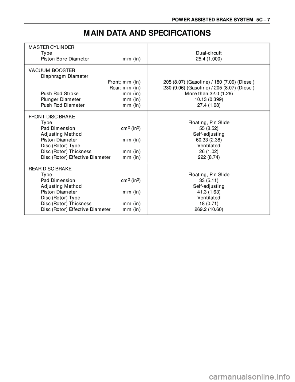
POWER ASSISTED BRAKE SYSTEM 5C – 7
MAIN DATA AND SPECIFICATIONS
MASTER CYLINDER
Type Dual-circuit
Piston Bore Diameter mm (in) 25.4 (1.000)
VACUUM BOOSTER
Diaphragm Diameter
Front; mm (in) 205 (8.07) (Gasoline) / 180 (7.09) (Diesel)
Rear; mm (in) 230 (9.06) (Gasoline) / 205 (8.07) (Diesel)
Push Rod Stroke mm (in) More than 32.0 (1.26)
Plunger Diameter mm (in) 10.13 (0.399)
Push Rod Diameter mm (in) 27.4 (1.08)
FRONT DISC BRAKE
Type Floating, Pin Slide
Pad Dimension cm
2(in2) 55 (8.52)
Adjusting Method Self-adjusting
Piston Diameter mm (in) 60.33 (2.38)
Disc (Rotor) Type Ventilated
Disc (Rotor) Thickness mm (in) 26 (1.02)
Disc (Rotor) Effective Diameter mm (in) 222 (8.74)
REAR DISC BRAKE
Type Floating, Pin Slide
Pad Dimension cm
2(in2) 33 (5.11)
Adjusting Method Self-adjusting
Piston Diameter mm (in) 41.3 (1.63)
Disc (Rotor) Type Ventilated
Disc (Rotor) Thickness mm (in) 18 (0.71)
Disc (Rotor) Effective Diameter mm (in) 269.2 (10.60)