instrument panel ISUZU TROOPER 1998 Service Repair Manual
[x] Cancel search | Manufacturer: ISUZU, Model Year: 1998, Model line: TROOPER, Model: ISUZU TROOPER 1998Pages: 3573, PDF Size: 60.36 MB
Page 26 of 3573
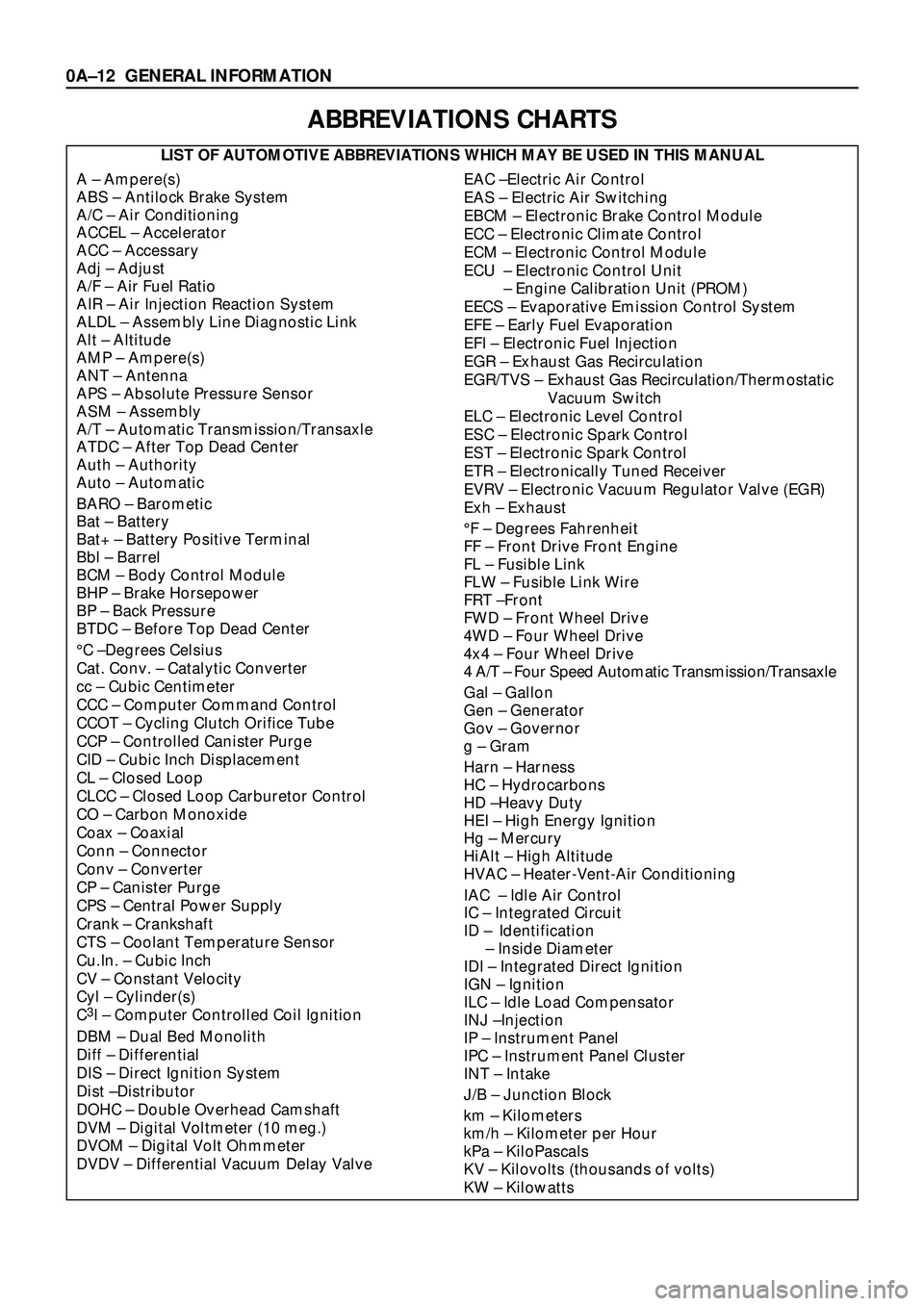
ABBREVIATIONS CHARTS
LIST OF AUTOMOTIVE ABBREVIATIONS WHICH MAY BE USED IN THIS MANUAL
A Ð Ampere(s)
ABS Ð Antilock Brake System
A/C Ð Air Conditioning
ACCEL Ð Accelerator
ACC Ð Accessary
Adj Ð Adjust
A/F Ð Air Fuel Ratio
AIR Ð Air Injection Reaction System
ALDL Ð Assembly Line Diagnostic Link
Alt Ð Altitude
AMP Ð Ampere(s)
ANT Ð Antenna
APS Ð Absolute Pressure Sensor
ASM Ð Assembly
A/T Ð Automatic Transmission/Transaxle
ATDC Ð After Top Dead Center
Auth Ð Authority
Auto Ð Automatic
BARO Ð Barometic
Bat Ð Battery
Bat+ Ð Battery Positive Terminal
Bbl Ð Barrel
BCM Ð Body Control Module
BHP Ð Brake Horsepower
BP Ð Back Pressure
BTDC Ð Before Top Dead Center
¡C ÐDegrees Celsius
Cat. Conv. Ð Catalytic Converter
cc Ð Cubic Centimeter
CCC Ð Computer Command Control
CCOT Ð Cycling Clutch Orifice Tube
CCP Ð Controlled Canister Purge
CID Ð Cubic Inch Displacement
CL Ð Closed Loop
CLCC Ð Closed Loop Carburetor Control
CO Ð Carbon Monoxide
Coax Ð Coaxial
Conn Ð Connector
Conv Ð Converter
CP Ð Canister Purge
CPS Ð Central Power Supply
Crank Ð Crankshaft
CTS Ð Coolant Temperature Sensor
Cu.In. Ð Cubic Inch
CV Ð Constant Velocity
Cyl Ð Cylinder(s)
C
3I Ð Computer Controlled Coil Ignition
DBM Ð Dual Bed Monolith
Diff Ð Differential
DIS Ð Direct Ignition System
Dist ÐDistributor
DOHC Ð Double Overhead Camshaft
DVM Ð Digital Voltmeter (10 meg.)
DVOM Ð Digital Volt Ohmmeter
DVDV Ð Differential Vacuum Delay Valve
EAC ÐElectric Air Control
EAS Ð Electric Air Switching
EBCM Ð Electronic Brake Control Module
ECC Ð Electronic Climate Control
ECM Ð Electronic Control Module
ECU Ð Electronic Control Unit
Ð Engine Calibration Unit (PROM)
EECS Ð Evaporative Emission Control System
EFE Ð Early Fuel Evaporation
EFI Ð Electronic Fuel Injection
EGR Ð Exhaust Gas Recirculation
EGR/TVS Ð Exhaust Gas Recirculation/Thermostatic
Vacuum Switch
ELC Ð Electronic Level Control
ESC Ð Electronic Spark Control
EST Ð Electronic Spark Control
ETR Ð Electronically Tuned Receiver
EVRV Ð Electronic Vacuum Regulator Valve (EGR)
Exh Ð Exhaust
¡F Ð Degrees Fahrenheit
FF Ð Front Drive Front Engine
FL Ð Fusible Link
FLW Ð Fusible Link Wire
FRT ÐFront
FWD Ð Front Wheel Drive
4WD Ð Four Wheel Drive
4x4 Ð Four Wheel Drive
4 A/T Ð Four Speed Automatic Transmission/Transaxle
Gal Ð Gallon
Gen Ð Generator
Gov Ð Governor
g Ð Gram
Harn Ð Harness
HC Ð Hydrocarbons
HD ÐHeavy Duty
HEI Ð High Energy Ignition
Hg Ð Mercury
HiAlt Ð High Altitude
HVAC Ð Heater-Vent-Air Conditioning
IAC Ð Idle Air Control
IC Ð Integrated Circuit
ID Ð Identification
Ð Inside Diameter
IDI Ð Integrated Direct Ignition
IGN Ð Ignition
ILC Ð Idle Load Compensator
INJ ÐInjection
IP Ð Instrument Panel
IPC Ð Instrument Panel Cluster
INT Ð Intake
J/B Ð Junction Block
km Ð Kilometers
km/h Ð Kilometer per Hour
kPa Ð KiloPascals
KV Ð Kilovolts (thousands of volts)
KW Ð Kilowatts
0AÐ12 GENERAL INFORMATION
Page 101 of 3573
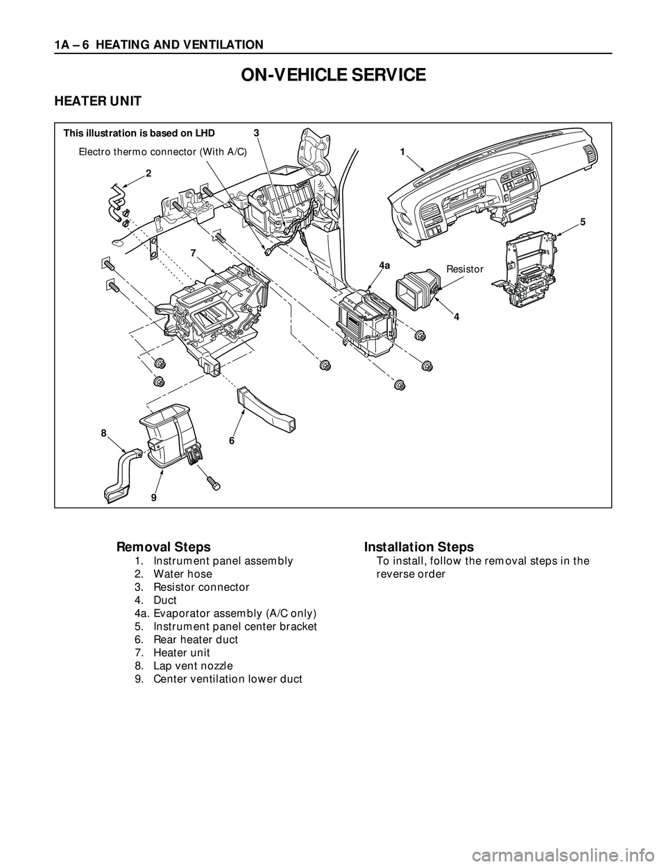
1A Ð 6 HEATING AND VENTILATION
ON-VEHICLE SERVICE
HEATER UNIT
4a
5
3
4
2
6
9
8
7
1Electro thermo connector (With A/C)
Resistor
Removal Steps
1. Instrument panel assembly
2. Water hose
3. Resistor connector
4. Duct
4a. Evaporator assembly (A/C only)
5. Instrument panel center bracket
6. Rear heater duct
7. Heater unit
8. Lap vent nozzle
9. Center ventilation lower duct
Installation Steps
To install, follow the removal steps in the
reverse order
This illustration is based on LHD
Page 102 of 3573
HEATING AND VENTILATION 1A Ð 7
INSTALLATION
To install, follow the removal steps in the reverse order,
noting the following points:
1. When handling the ECM and the control unit, be
careful not to make any improper connection of the
connectors.
2. Adjust control lever assembly cables.
Refer to ÒCONTROL LEVER ASSEMBLYÓ installation
steps in this section.
3. When installing the heater unit, defroster nozzle and
center vent duct, be sure that proper seal is made,
without any gap between then.
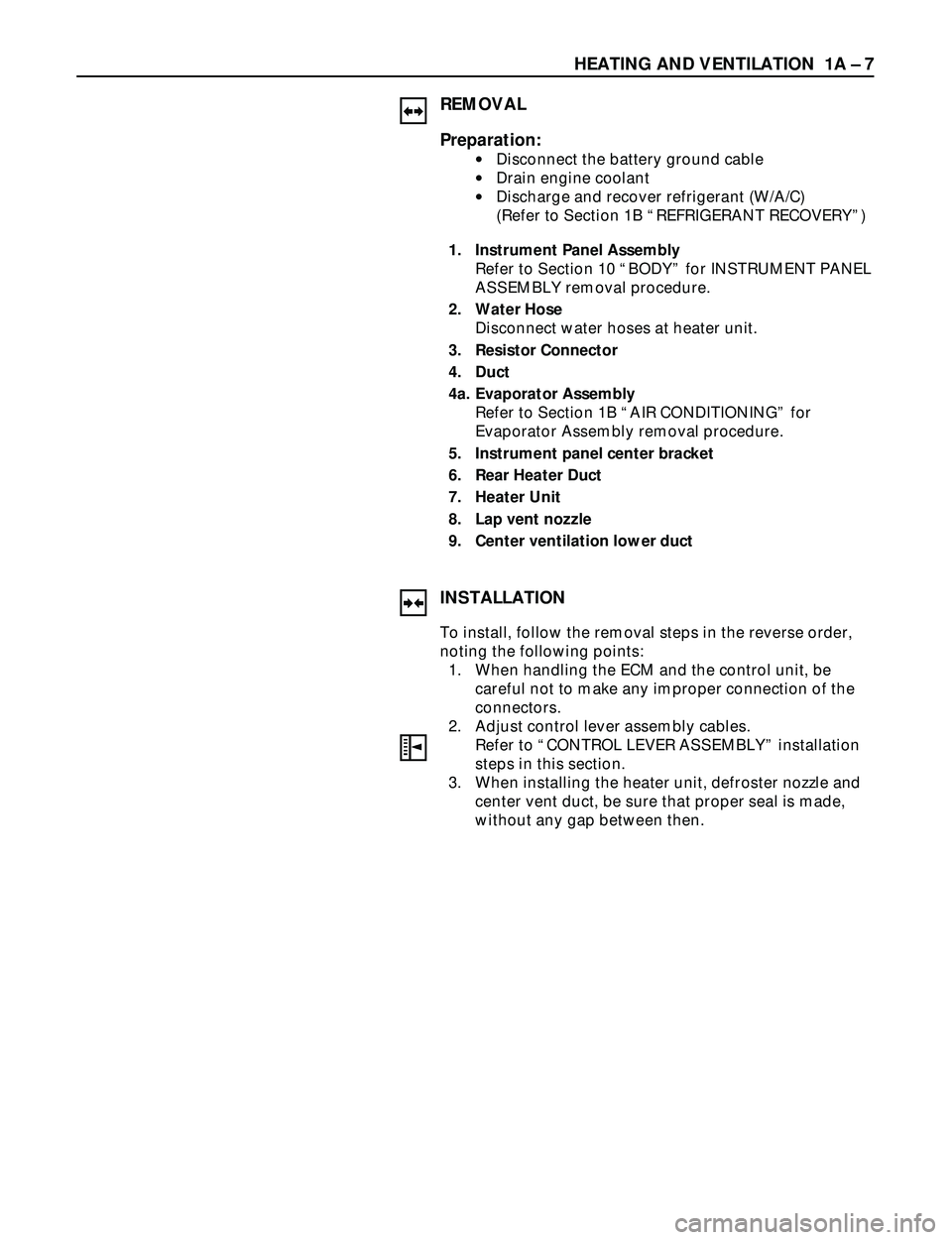
REMOVAL
Preparation:
·Disconnect the battery ground cable
·Drain engine coolant
·Discharge and recover refrigerant (W/A/C)
(Refer to Section 1B ÒREFRIGERANT RECOVERYÓ)
1. Instrument Panel Assembly
Refer to Section 10 ÒBODYÓ for INSTRUMENT PANEL
ASSEMBLY removal procedure.
2. Water Hose
Disconnect water hoses at heater unit.
3. Resistor Connector
4. Duct
4a. Evaporator Assembly
Refer to Section 1B ÒAIR CONDITIONINGÓ for
Evaporator Assembly removal procedure.
5. Instrument panel center bracket
6. Rear Heater Duct
7. Heater Unit
8. Lap vent nozzle
9. Center ventilation lower duct
Page 109 of 3573
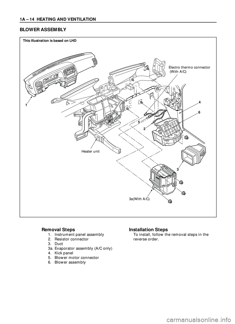
1A Ð 14 HEATING AND VENTILATION
Removal Steps
1. Instrument panel assembly
2. Resistor connector
3. Duct
3a. Evaporator assembly (A/C only)
4. Kick panel
5. Blower motor connector
6. Blower assembly
Installation Steps
To install, follow the removal steps in the
reverse order.
BLOWER ASSEMBLY
2
3a(With A/C)
3
Heater unit
Electro thermo connector
(With A/C)
14
6
5
This illustration is based on LHD
Page 110 of 3573
HEATING AND VENTILATION 1A Ð 15
REMOVAL
Preparation:
·Disconnect the battery ground cable
·Discharge and recover refrigerant (W/A/C)
(Refer to Section 1B ÒREFRIGERANT RECOVERYÓ)
1. Instrument Panel Assembly
Refer to Section 10 ÒBODYÓ for INSTRUMENT PANEL
ASSEMBLY removal procedure.
2. Resistor Connector
3. Duct
3a. Evaporator Assembly (A/C only)
Refer to Section 1B ÒAIR CONDITIONINGÓ for
EVAPORATOR ASSEMBLY removal procedure.
4. Kick panel
5. Blower Motor Connector
6. Blower Assembly
INSTALLATION
To install, follow the removal steps in the reverse order,
noting the following point:
1. Adjust Control Lever Assembly Cables
Refer to ÒCONTROL LEVER ASSEMBLYÓ installation
procedure in this section.
Page 115 of 3573
1A Ð 20 HEATING AND VENTILATION
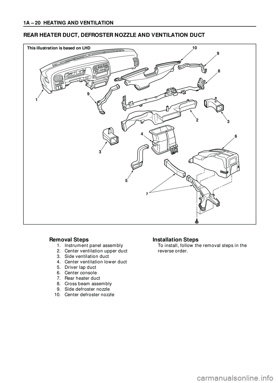
REAR HEATER DUCT, DEFROSTER NOZZLE AND VENTILATION DUCT
Removal Steps
1. Instrument panel assembly
2. Center ventilation upper duct
3. Side ventilation duct
4. Center ventilation lower duct
5. Driver lap duct
6. Center console
7. Rear heater duct
8. Cross beam assembly
9. Side defroster nozzle
10. Center defroster nozzle
Installation Steps
To install, follow the removal steps in the
reverse order.
7
9
9
10
8
6
3
5
1
3
4
2
This illustration is based on LHD
Page 116 of 3573
HEATING AND VENTILATION 1A Ð 21
INSTALLATION
To install, follow the removal steps in the reverse order,
noting the following point:
1. Connect each duct and nozzle securely leaving no
clearance between them and making no improper
matching.
REMOVAL
Preparation:
Disconnect the battery ground cable
1. Instrument panel assembly
·Refer to Section 10 ÒBODYÓ for INSTRUMENT
PANEL ASSEMBLY removal procedure.
2. Center ventilation upper duct
3. Side ventilation duct
4. Center ventilation lower duct
5. Driver lap duct
6. Center console
7. Rear heater duct
·Refer to Section 10 ÒBODYÓ for CONSOLES
removal procedure.
8. Cross beam assembly
·Refer to Section 10 ÒBODYÓ for CROSS BEAM
ASSEMBLY removal procedure.
9. Side defroster nozzle
10. Center defroster nozzle
Page 117 of 3573
1A Ð 22 HEATING AND VENTILATION
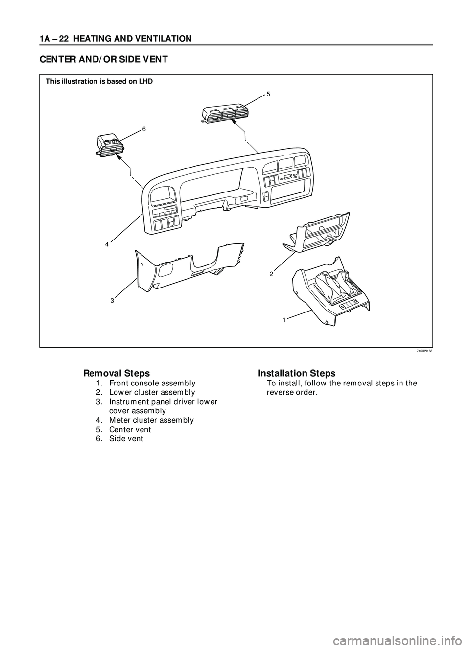
Removal Steps
1. Front console assembly
2. Lower cluster assembly
3. Instrument panel driver lower
cover assembly
4. Meter cluster assembly
5. Center vent
6. Side vent
Installation Steps
To install, follow the removal steps in the
reverse order.
CENTER AND/OR SIDE VENT
6
5
3
1 2
4
This illustration is based on LHD
740RW168
Page 118 of 3573
HEATING AND VENTILATION 1A Ð 23
INSTALLATION
To install, follow the removal steps in the reverse order.
REMOVAL
1. Front console assembly
2. Lower cluster assembly
3. Instrument panel driver lower cover assembly
4. Meter cluster assembly
·Refer to Section 10 ÒBODYÓ for INSTRUMENT
PANEL ASSEMBLY removal procedure.
5. Center vent
·Remove screws and the center vent from center
cluster while prying up the center vent catch
portions.
6. Side vent
·Remove screws and the side vent from center
cluster while prying up the side vent catch
portions.
Page 119 of 3573
1A Ð 24 HEATING AND VENTILATION
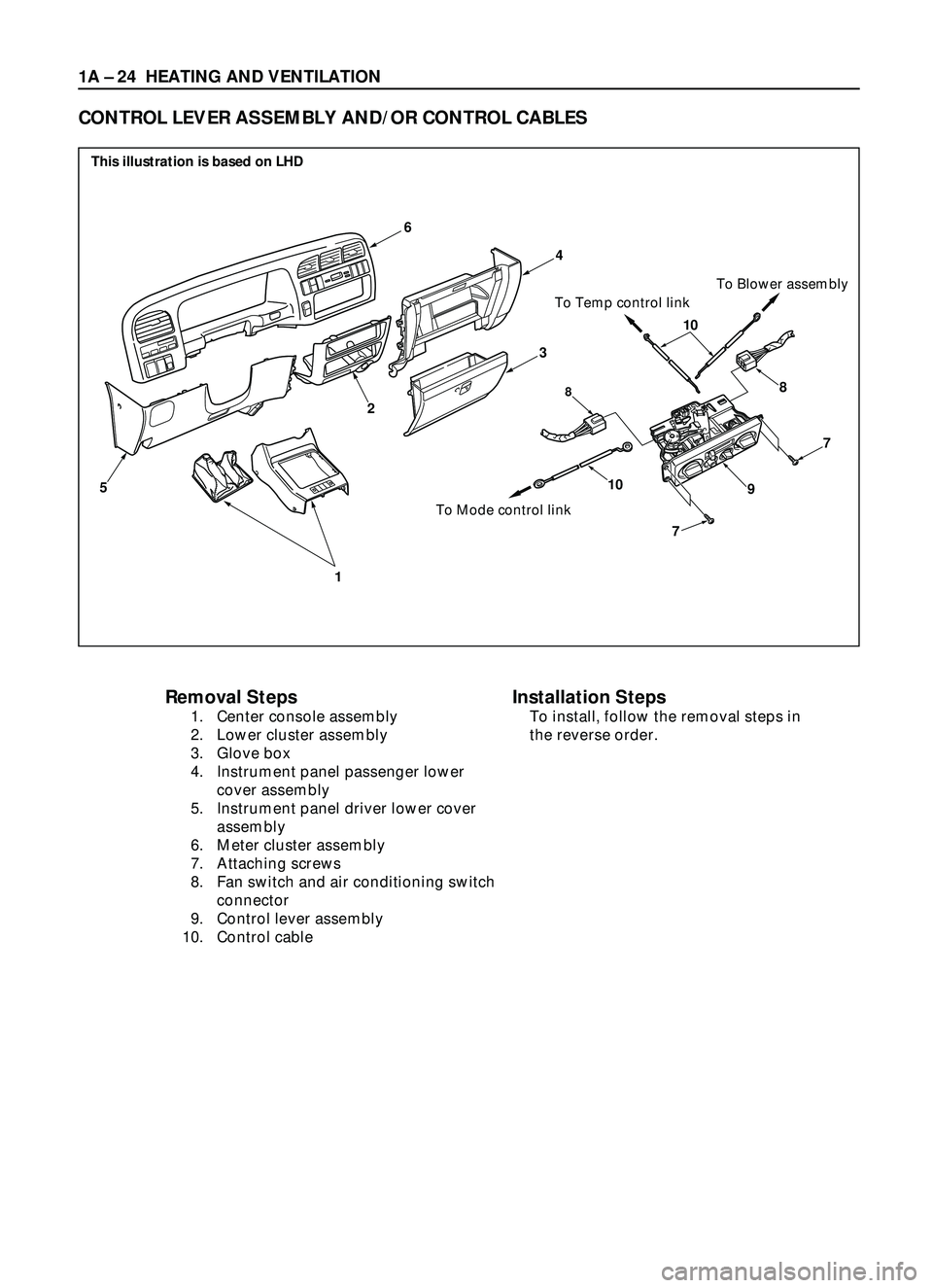
Removal Steps
1. Center console assembly
2. Lower cluster assembly
3. Glove box
4. Instrument panel passenger lower
cover assembly
5. Instrument panel driver lower cover
assembly
6. Meter cluster assembly
7. Attaching screws
8. Fan switch and air conditioning switch
connector
9. Control lever assembly
10. Control cable
CONTROL LEVER ASSEMBLY AND/OR CONTROL CABLES
6
1
5
2
10
7
7
88
910
To Mode control linkTo Temp control linkTo Blower assembly
4
3
Installation Steps
To install, follow the removal steps in
the reverse order.
This illustration is based on LHD