light ISUZU TROOPER 1998 Service Repair Manual
[x] Cancel search | Manufacturer: ISUZU, Model Year: 1998, Model line: TROOPER, Model: ISUZU TROOPER 1998Pages: 3573, PDF Size: 60.36 MB
Page 12 of 3573
PAGE BACK PAGE NEXT
THIS MALUAL INCLUDES THE FOLLOWING SECTIONS:
SECTION No. CONTRNTS
8A LIGHTING SYSTEM
8B WIPER / WASHER SYSTEM
8C ENTERTAINMENT
8D WIRING SYSTEM
8E METER AND GAUGE
8F BODY STRUCTURE
8G SEATS
8H SECURITY AND LOCKS
8I SUN ROOF/CONVERTIBLE TOP
8J EXTERIOR / INTERIOR TRIM
Page 35 of 3573
0BÐ8 MAINTENANCE AND LUBRICATION
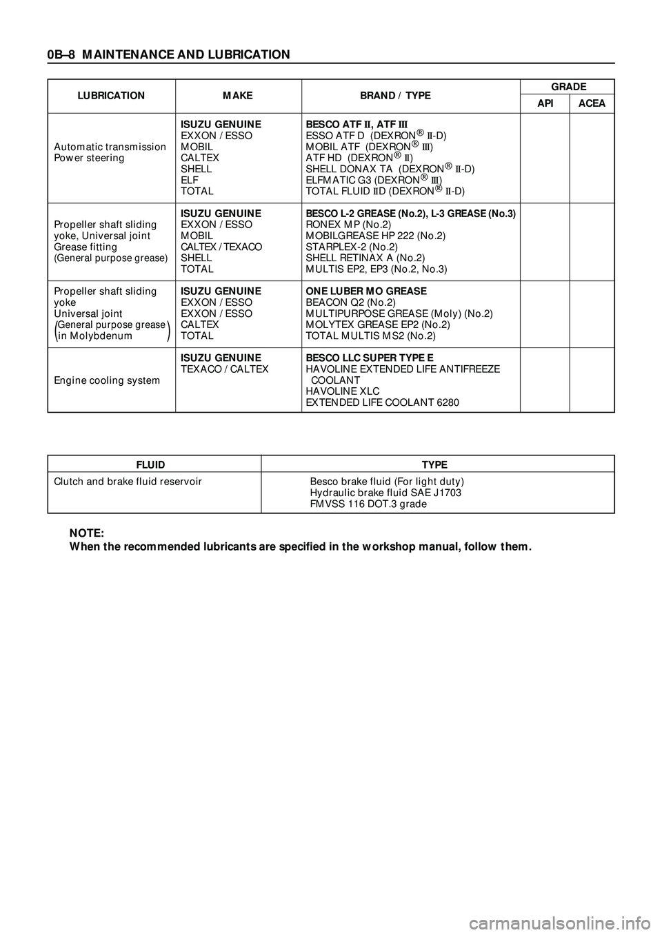
FLUID TYPE
Clutch and brake fluid reservoir Besco brake fluid (For light duty)
Hydraulic brake fluid SAE J1703
FMVSS 116 DOT.3 grade
LUBRICATION MAKE BRAND / TYPEGRADE
API ACEA
ISUZU GENUINE BESCO ATF II, ATF III
EXXON / ESSO ESSO ATF D (DEXRONÒ
II-D)
Automatic transmission MOBIL MOBIL ATF (DEXRONÒ
III)
Power steering CALTEX ATF HD (DEXRONÒ
II)
SHELL SHELL DONAX TA (DEXRONÒ
II-D)
ELF ELFMATIC G3 (DEXRONÒ
III)
TOTAL TOTAL FLUID IID (DEXRONÒ
II-D)
ISUZU GENUINE
BESCO L-2 GREASE (No.2), L-3 GREASE (No.3)Propeller shaft sliding EXXON / ESSO RONEX MP (No.2)
yoke, Universal joint MOBIL MOBILGREASE HP 222 (No.2)
Grease fittingCALTEX / TEXACOSTARPLEX-2 (No.2)
(General purpose grease)SHELL SHELL RETINAX A (No.2)
TOTAL MULTIS EP2, EP3 (No.2, No.3)
Propeller shaft slidingISUZU GENUINE ONE LUBER MO GREASE
yoke EXXON / ESSO BEACON Q2 (No.2)
Universal joint EXXON / ESSO MULTIPURPOSE GREASE (Moly) (No.2)
General purpose greaseCALTEX MOLYTEX GREASE EP2 (No.2)(in Molybdenum)TOTAL TOTAL MULTIS MS2 (No.2)
ISUZU GENUINE BESCO LLC SUPER TYPE E
TEXACO / CALTEX HAVOLINE EXTENDED LIFE ANTIFREEZE
Engine cooling system COOLANT
HAVOLINE XLC
EXTENDED LIFE COOLANT 6280
NOTE:
When the recommended lubricants are specified in the workshop manual, follow them.
Page 131 of 3573
AIR CONDITIONING 1B Ð 5
With some compressors the differential between
the intake pressure and discharge pressure
generated while the compressor is operating is
used for lubrication instead of an oil pump.
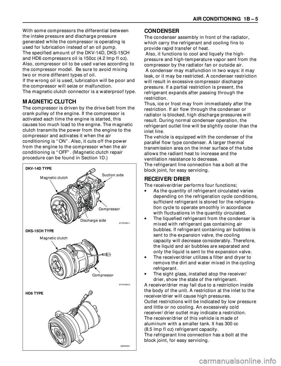
The specified amount of the DKV-14D, DKS-15CH
and HD6 compressors oil is 150cc (4.2 Imp fl oz).
Also, compressor oil to be used varies according to
the compressor model. Be sure to avoid mixing
two or more different types of oil.
If the wrong oil is used, lubrication will be poor and
the compressor will seize or malfunction.
The magnetic clutch connector is a waterproof type.
MAGNETIC CLUTCH
The compressor is driven by the drive belt from the
crank pulley of the engine. If the compressor is
activated each time the engine is started, this
causes too much load to the engine. The magnetic
clutch transmits the power from the engine to the
compressor and activates it when the air
conditioning is ÒONÓ. Also, it cuts off the power
from the engine to the compressor when the air
conditioning is ÒOFFÓ. (Magnetic clutch repair
procedure can be found in Section 1D.)
CONDENSER
The condenser assembly in front of the radiator,
which carry the refrigerant and cooling fins to
provide rapid transfer of heat.
Also, it functions to cool and liquefy the high-
pressure and high-temperature vapor sent from the
compressor by the radiator fan or outside air.
A condenser may malfunction in two ways: it may
leak, or it may be restricted. A condenser restriction
will result in excessive compressor discharge
pressure. If a partial restriction is present, the
refrigerant expands after passing through the
restriction.
Thus, ice or frost may from immediately after the
restriction. If air flow through the condenser or
radiator is blocked, high discharge pressures will
result. During normal condenser operation, the
refrigerant outlet line will be slightly cooler than the
inlet line.
The vehicle is equipped with the condenser of the
parallel flow type condenser. A larger thermal
transmission area on the inner surface of the tube
allows the radiant heat to increase and the
ventilation resistance to decrease.
The refrigerant line connection has a bolt at the
block joint, for easy servicing.
RECEIVER/DRIER
The receiver/drier performs four functions;
·As the quantity of refrigerant circulated varies
depending on the refrigeration cycle conditions,
sufficient refrigerant is stored for the refrigera-
tion cycle to operate smoothly in accordance
with fluctuations in the quantity circulated.
·The liquefied refrigerant from the condenser is
mixed with refrigerant gas containing air
bubbles. If refrigerant containing air bubbles is
sent to the expansion valve, the cooling
capacity will decrease considerably. Therefore,
the liquid and air bubbles are separated and
only the liquid is sent to the expansion valve.
·The receiver/drier utilizes a filter and dryer to
remove the dirt and water mixed in the cycling
refrigerant.
·The sight glass, installed atop the receiver/
drier, show the state of the refrigerant.
A receiver/drier may fail due to a restriction inside
the body of the unit. A restriction at the inlet to the
receiver/drier will cause high pressures.
Outlet restrictions will be indicated by low pressure
and little or no cooling. An excessively cold
receiver/ drier outlet may indicate a restriction.
The receiver/drier of this vehicle is made of
aluminum with a smaller tank. It has 300 cc
(8.5 Imp fl oz) refrigerant capacity.
The refrigerant line connection has a bolt at the
block joint, for easy servicing.
DKV-14D TYPE
DKS-15CH TYPE
HD6 TYPE
Magnetic clutch
CompressorSuction side
Discharge side
Compressor Magnetic clutch
852RW031 871RY00012
871RY00011
Page 147 of 3573
AIR CONDITIONING 1B Ð 21
8) Charge the system to the specified amount and then
close the low-pressure hand valve.
Refrigerant Amount g(lbs.)
750 (1.65)
DELPH1HD6/HT6 g(lbs.)
600 (1.32)
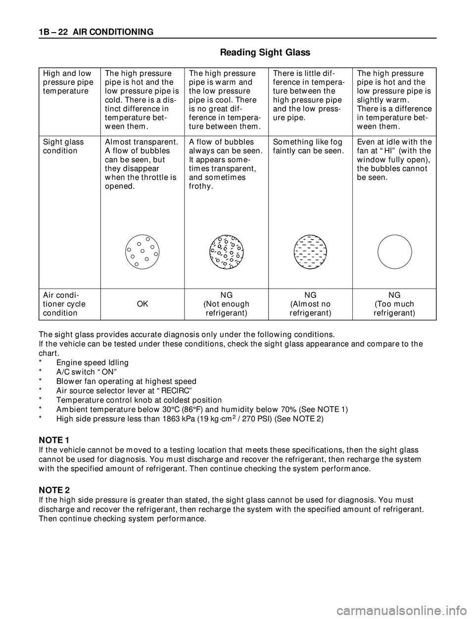
·A fully charged system is indicated by the sight
glass on the receiver/driver being free of any.
bubbles(Refer to ÒReading Sight GlassÓ).
·Check the high and low pressure value of the
manifold gauge.
·Check for refrigerant leaks by using a HFC-134a
leak detector.
Immediately after charging refrigerant, both high and low
pressures are slightly high and to the left of the gauge, but
they settle down to the guide pressure valves as shown
below:
·Ambient temperature; 25 ~30¡C (77 ~86¡F)
·Guide pressure
High-pressure side;
Approx. 1373 Ð 1863 kPa (14 Ð 19 kgácm
2/ 199 Ð 270 PSI)
Low-pressure side;
Approx. 147 Ð 294 kPa (1.4 Ð 3.0 kgácm
2/ 21 Ð 43 PSI)
9) Close the low pressure hand valve and charge valve
of the refrigerant container.
10) Stop the air conditioning and the engine.
11) Disconnect the high and low pressure hoses from the
manifold gauge fittings.
Page 148 of 3573
1B Ð 22 AIR CONDITIONING
Almost transparent.
A flow of bubbles
can be seen, but
they disappear
when the throttle is
opened.
The sight glass provides accurate diagnosis only under the following conditions.
If the vehicle can be tested under these conditions, check the sight glass appearance and compare to the
chart.
* Engine speed Idling
* A/C switch ÒONÓ
* Blower fan operating at highest speed
* Air source selector lever at ÒRECIRCÓ
* Temperature control knob at coldest position
* Ambient temperature below 30¡C (86¡F) and humidity below 70% (See NOTE 1)
* High side pressure less than 1863 kPa (19 kgácm
2/ 270 PSI) (See NOTE 2)
NOTE 1
If the vehicle cannot be moved to a testing location that meets these specifications, then the sight glass
cannot be used for diagnosis. You must discharge and recover the refrigerant, then recharge the system
with the specified amount of refrigerant. Then continue checking the system performance.
NOTE 2
If the high side pressure is greater than stated, the sight glass cannot be used for diagnosis. You must
discharge and recover the refrigerant, then recharge the system with the specified amount of refrigerant.
Then continue checking system performance.
Reading Sight Glass
High and low
pressure pipe
temperature
Sight glass
condition
Air condi-
tioner cycle
condition
The high pressure
pipe is hot and the
low pressure pipe is
cold. There is a dis-
tinct difference in
temperature bet-
ween them.
OK
The high pressure
pipe is warm and
the low pressure
pipe is cool. There
is no great dif-
ference in tempera-
ture between them.
A flow of bubbles
always can be seen.
It appears some-
times transparent,
and sometimes
frothy.
NG
(Not enough
refrigerant)
There is little dif-
ference in tempera-
ture between the
high pressure pipe
and the low press-
ure pipe.
Something like fog
faintly can be seen.
NG
(Almost no
refrigerant)
The high pressure
pipe is hot and the
low pressure pipe is
slightly warm.
There is a difference
in temperature bet-
ween them.
Even at idle with the
fan at ÒHIÓ (with the
window fully open),
the bubbles cannot
be seen.
NG
(Too much
refrigerant)
Page 219 of 3573
AIR CONDITIONING 1BÐ93
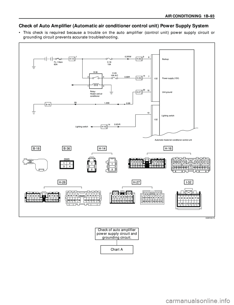
Check of Auto Amplifier (Automatic air conditioner control unit) Power Supply System
¥ This check is required because a trouble on the auto amplifier (control unit) power supply circuit or
grounding circuit prevents accurate troubleshooting.
Check of auto amplifier
power supply circuit and
grounding circuit.
Chart A
B-18
FL-1 Main
80A
0.5G/R16
107 8
I-32
I-32 C-16
10A0.3R/W
0.5BRBackup
Power supply (12V)
Unit ground
Automatic heater/air conditioner control unit
B-18B-36H-14
C-20
10A A/C
Relay:
Heater and air
conditioner
0.5B
1.25B 2B
Lighting switchLighting switch
H-141H-269
H-2614
H-2720
H-1614 2
14
3 B-36
12
34
H-16
H-26H-27I-32
1
2
1
2
10987654321
222120191815141312111716
12345111213141567891018192021221617
10 11 12 13 14 151234 5
17 18 19 206789
16
9876
20 19 18 17 165
14 154
133
122
111
10
20 12
19 11
18 10
179
168
157
146
13512 34
43 21
12111098765
13 14 15 16 17 18 19 20
12345678
9 10111213141516
D08RY00175
Page 220 of 3573
1BÐ94 AIR CONDITIONING
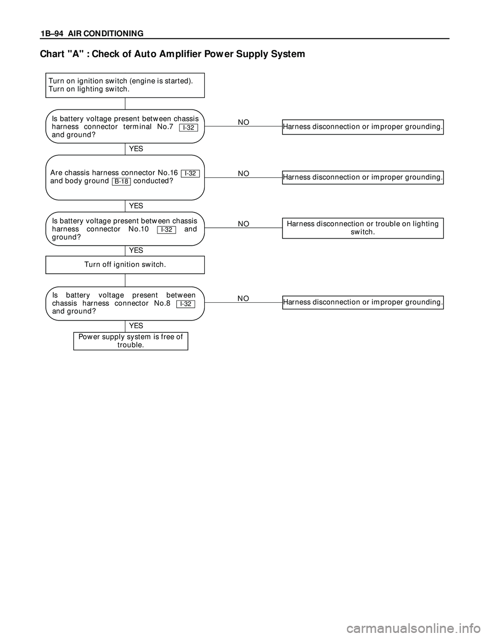
Chart "A" : Check of Auto Amplifier Power Supply System
NOHarness disconnection or improper grounding.
NOHarness disconnection or improper grounding.
NOHarness disconnection or trouble on lighting
switch.
NOHarness disconnection or improper grounding.
Turn off ignition switch.
Power supply system is free of
trouble.
YES YES
YES YES
Is battery voltage present between chassis
harness connector terminal No.7
and ground?
I-32
Is battery voltage present between
chassis harness connector No.8
and ground?
I-32
Are chassis harness connector No.16
and body ground conducted?
B-18I-32
Turn on ignition switch (engine is started).
Turn on lighting switch.
Is battery voltage present between chassis
harness connector No.10 and
ground?
I-32
Page 223 of 3573
AIR CONDITIONING 1BÐ97
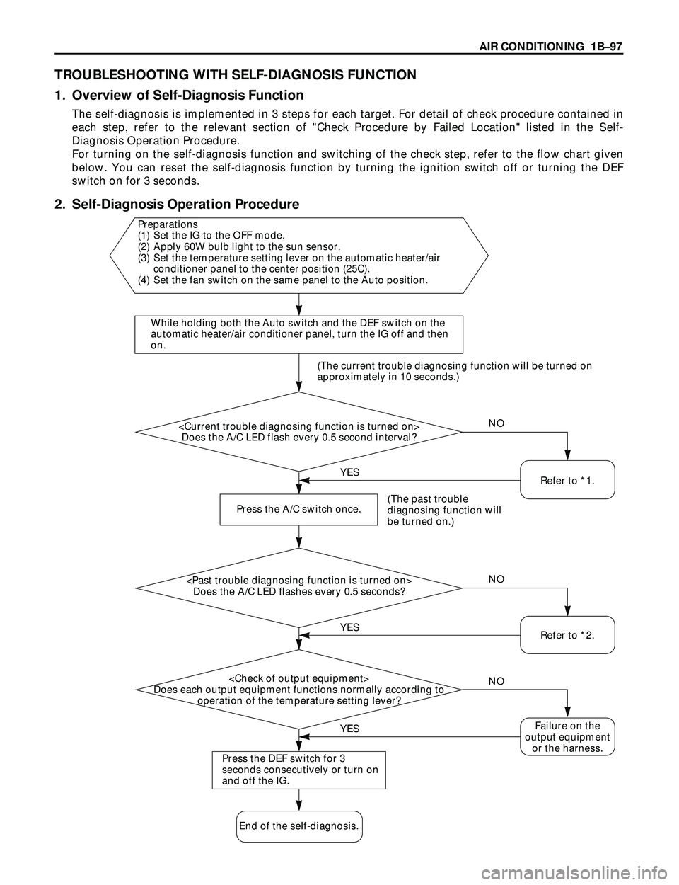
TROUBLESHOOTING WITH SELF-DIAGNOSIS FUNCTION
1. Overview of Self-Diagnosis Function
The self-diagnosis is implemented in 3 steps for each target. For detail of check procedure contained in
each step, refer to the relevant section of "Check Procedure by Failed Location" listed in the Self-
Diagnosis Operation Procedure.
For turning on the self-diagnosis function and switching of the check step, refer to the flow chart given
below. You can reset the self-diagnosis function by turning the ignition switch off or turning the DEF
switch on for 3 seconds.
2. Self-Diagnosis Operation Procedure
While holding both the Auto switch and the DEF switch on the
automatic heater/air conditioner panel, turn the IG off and then
on.
Does the A/C LED flash every 0.5 second interval?
Press the A/C switch once.
(The past trouble
diagnosing function will
be turned on.)
Does the A/C LED flashes every 0.5 seconds?
Does each output equipment functions normally according to
operation of the temperature setting lever?
Press the DEF switch for 3
seconds consecutively or turn on
and off the IG.
Failure on the
output equipment
or the harness.
Preparations
(1) Set the IG to the OFF mode.
(2) Apply 60W bulb light to the sun sensor.
(3) Set the temperature setting lever on the automatic heater/air
conditioner panel to the center position (25C).
(4) Set the fan switch on the same panel to the Auto position.
End of the self-diagnosis.(The current trouble diagnosing function will be turned on
approximately in 10 seconds.)
YESNO
YESNO
NO
YES
Refer to *1.
Refer to *2.
Page 224 of 3573
1BÐ98 AIR CONDITIONING
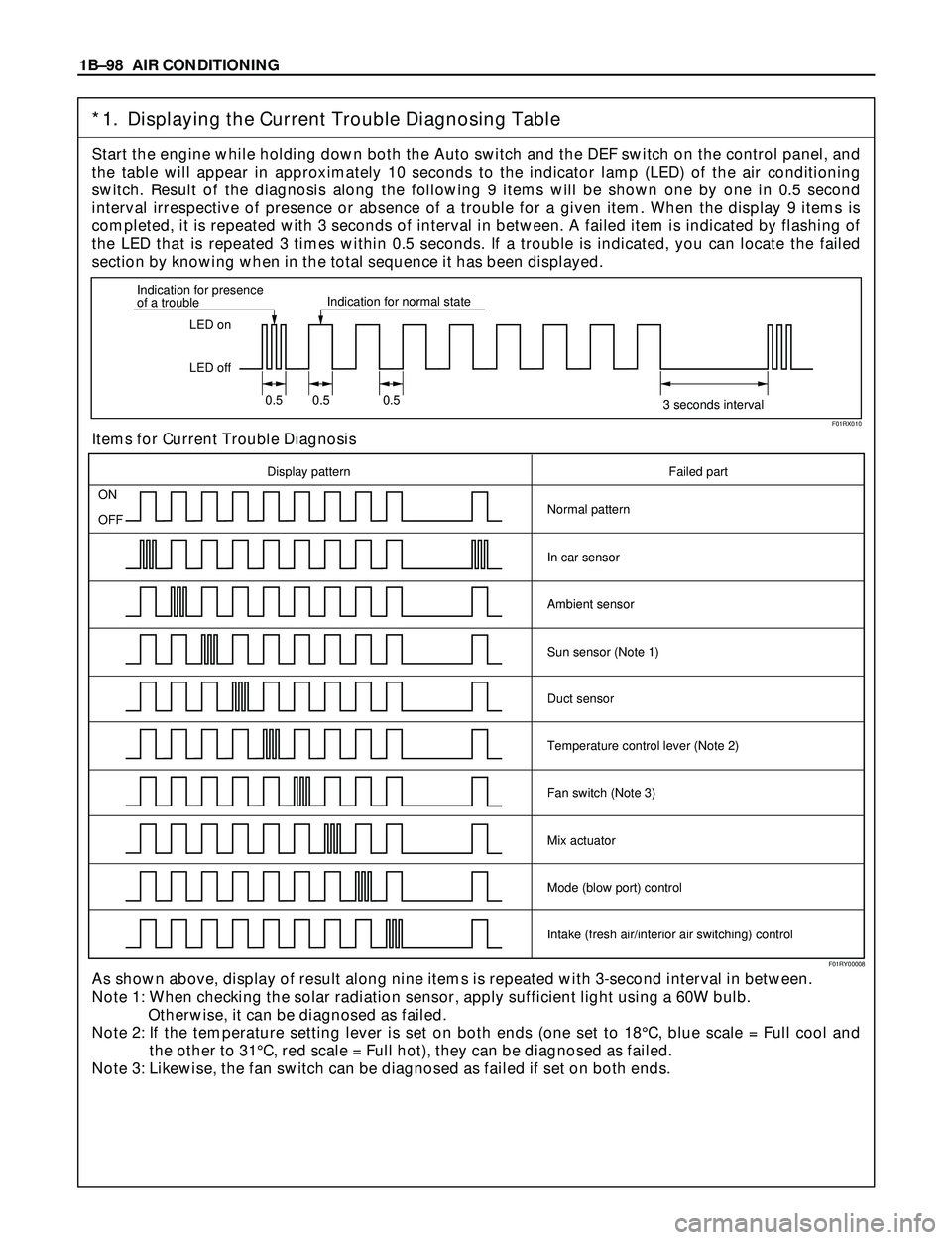
*1. Displaying the Current Trouble Diagnosing Table
Start the engine while holding down both the Auto switch and the DEF switch on the control panel, and
the table will appear in approximately 10 seconds to the indicator lamp (LED) of the air conditioning
switch. Result of the diagnosis along the following 9 items will be shown one by one in 0.5 second
interval irrespective of presence or absence of a trouble for a given item. When the display 9 items is
completed, it is repeated with 3 seconds of interval in between. A failed item is indicated by flashing of
the LED that is repeated 3 times within 0.5 seconds. If a trouble is indicated, you can locate the failed
section by knowing when in the total sequence it has been displayed.
Items for Current Trouble Diagnosis
As shown above, display of result along nine items is repeated with 3-second interval in between.
Note 1: When checking the solar radiation sensor, apply sufficient light using a 60W bulb.
Otherwise, it can be diagnosed as failed.
Note 2: If the temperature setting lever is set on both ends (one set to 18¡C, blue scale = Full cool and
the other to 31¡C, red scale = Full hot), they can be diagnosed as failed.
Note 3: Likewise, the fan switch can be diagnosed as failed if set on both ends.
LED on
LED off Indication for presence
of a troubleIndication for normal state
0.5 0.5 0.5
3 seconds interval
ON
OFF
Display pattern Failed part
Normal pattern
In car sensor
Ambient sensor
Sun sensor (Note 1)
Duct sensor
Temperature control lever (Note 2)
Fan switch (Note 3)
Mix actuator
Mode (blow port) control
Intake (fresh air/interior air switching) control
F01RX010
F01RY00008
Page 274 of 3573
1D Ð 18 COMPRESSOR OVERHAUL
HD6 TYPE COMPRESSOR
Metric Thread Size Information
Compressor to mounting bracket bolts (Front)
M10´ 1.5 Ð 6H
Compressor to mounting bracket bolts (Rear)
M8´ 1.25 Ð 6H
Suction-discharge port screw
M10´ 1.5 Ð 6HCompressor shaft
M9´ 1.25 Ð 6H
Internal hub-clutch drive assembly
M22´ 1.5 Ð 6H
COMPRESSOR CLUTCH PLATE AND HUB
ASSEMBLY
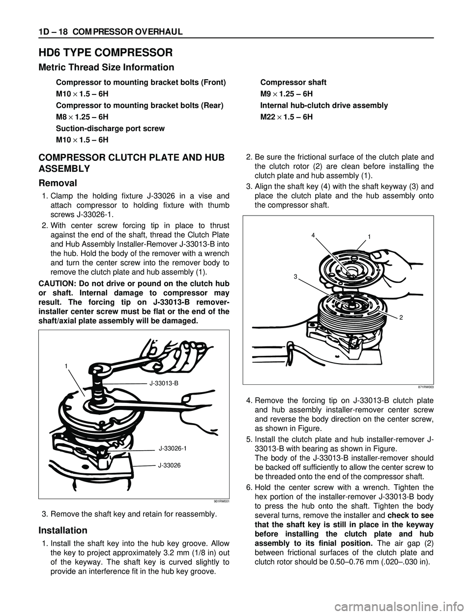
Removal
1. Clamp the holding fixture J-33026 in a vise and
attach compressor to holding fixture with thumb
screws J-33026-1.
2. With center screw forcing tip in place to thrust
against the end of the shaft, thread the Clutch Plate
and Hub Assembly Installer-Remover J-33013-B into
the hub. Hold the body of the remover with a wrench
and turn the center screw into the remover body to
remove the clutch plate and hub assembly (1).
CAUTION: Do not drive or pound on the clutch hub
or shaft. Internal damage to compressor may
result. The forcing tip on J-33013-B remover-
installer center screw must be flat or the end of the
shaft/axial plate assembly will be damaged.
3. Remove the shaft key and retain for reassembly.
Installation
1. Install the shaft key into the hub key groove. Allow
the key to project approximately 3.2 mm (1/8 in) out
of the keyway. The shaft key is curved slightly to
provide an interference fit in the hub key groove.2. Be sure the frictional surface of the clutch plate and
the clutch rotor (2) are clean before installing the
clutch plate and hub assembly (1).
3. Align the shaft key (4) with the shaft keyway (3) and
place the clutch plate and the hub assembly onto
the compressor shaft.
4. Remove the forcing tip on J-33013-B clutch plate
and hub assembly installer-remover center screw
and reverse the body direction on the center screw,
as shown in Figure.
5. Install the clutch plate and hub installer-remover J-
33013-B with bearing as shown in Figure.
The body of the J-33013-B installer-remover should
be backed off sufficiently to allow the center screw to
be threaded onto the end of the compressor shaft.
6. Hold the center screw with a wrench. Tighten the
hex portion of the installer-remover J-33013-B body
to press the hub onto the shaft. Tighten the body
several turns, remove the installer and check to see
that the shaft key is still in place in the keyway
before installing the clutch plate and hub
assembly to its finial position.The air gap (2)
between frictional surfaces of the clutch plate and
clutch rotor should be 0.50Ð0.76 mm (.020Ð.030 in).
1
J-33013-B
J-33026-1
J-33026
901RW001
4
31
2
871RW003