engine JAGUAR S TYPE 1999 1.G Powertrain Manual
[x] Cancel search | Manufacturer: JAGUAR, Model Year: 1999, Model line: S TYPE, Model: JAGUAR S TYPE 1999 1.GPages: 75, PDF Size: 3.4 MB
Page 66 of 75
Automatic TransmissionAJ-V6/AJ28
61
Introduction
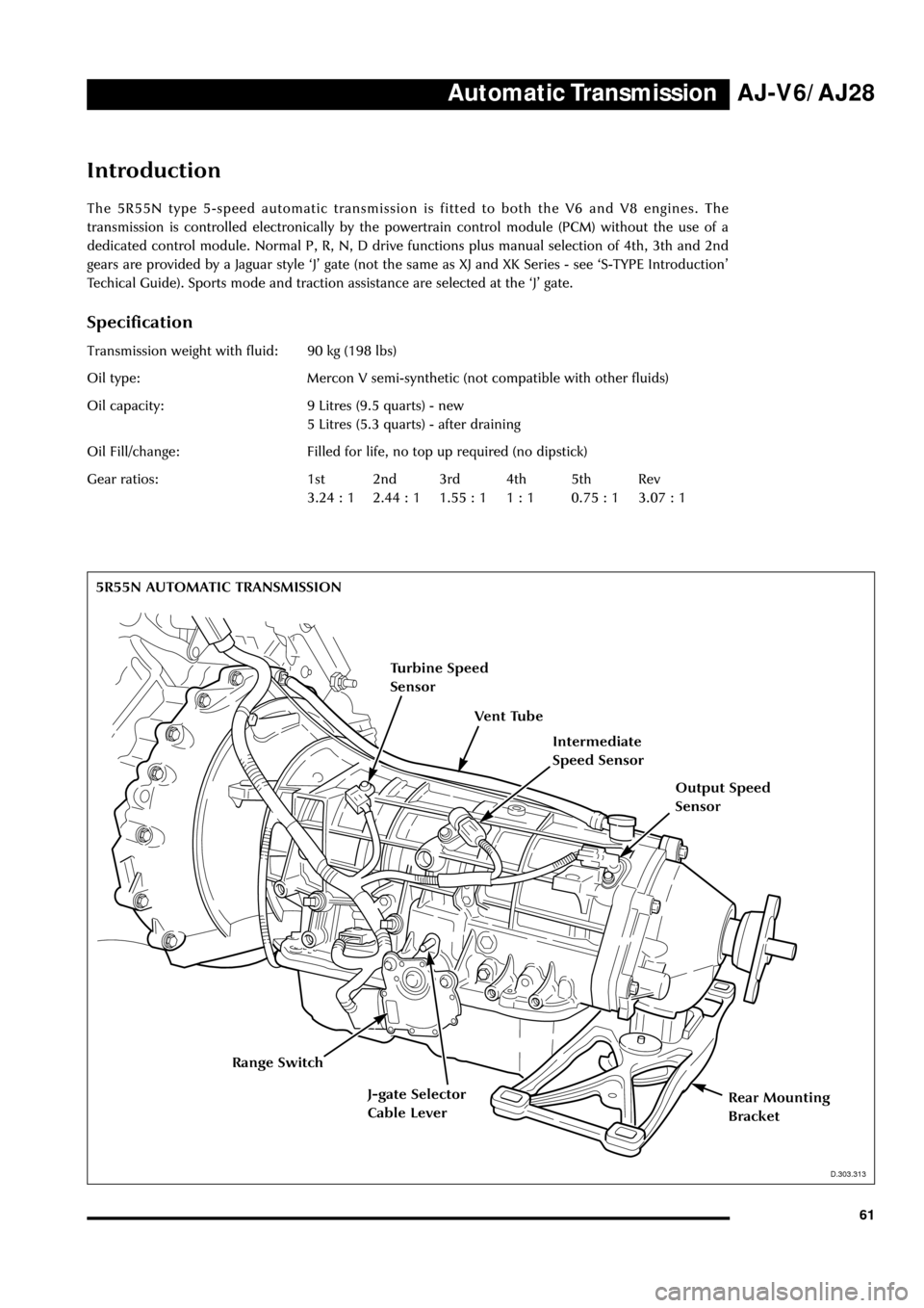
The 5R55N type 5-speed automatic transmission is fitted to both the V6 and V8 engines. The
transmission is controlled electronically by the powertrain control module (PCM) without the use of a
dedicated control module. Normal P, R, N, D drive functions plus manual selection of 4th, 3th and 2nd
gears are provided by a Jaguar style ÔJÕ gate (not the same as XJ and XK Series - see ÔS-TYPE IntroductionÕ
Techical Guide). Sports mode and traction assistance are selected at the ÔJÕ gate.
Specification
Transmission weight with fluid: 90 kg (198 lbs)
Oil type: Mercon V semi-synthetic (not compatible with other fluids)
Oil capacity: 9 Litres (9.5 quarts) - new
5 Litres (5.3 quarts) - after draining
Oil Fill/change: Filled for life, no top up required (no dipstick)
Gear ratios: 1st 2nd 3rd 4th 5th Rev
3.24 : 1 2.44 : 1 1.55 : 1 1 : 1 0.75 : 1 3.07 : 1
D.307.313
5R55N AUTOMATIC TRANSMISSION
D.303.313
Vent Tube
Turbine Speed
Sensor
Intermediate
Speed Sensor
Output Speed
Sensor
Range Switch
Rear Mounting
BracketJ-gate Selector
Cable Lever
Page 67 of 75
Automatic Transmission AJ-V6/AJ28
62
D.307.321
V8 Engine Adaptor Plate
D.307.321
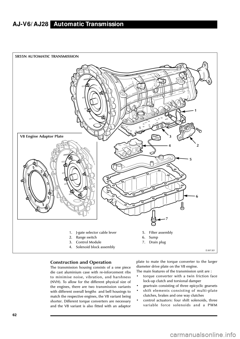
1. J-gate selector cable lever
2. Range switch
3. Control Module
4. Solenoid block assembly5. Filter assembly
6. Sump
7. Drain plug
Construction and Operation
The transmission housing consists of a one piece
die cast aluminium case with re-inforcement ribs
to minimise noise, vibration, and harshness
(NVH). To allow for the different physical size of
the engines, there are two transmission variants
with different overall lengths and bell housings to
match the respective engines, the V8 variant being
shorter. Different torque converters are necessary
and the V8 variant is also fitted with an adaptorplate to mate the torque converter to the larger
diameter drive plate on the V8 engine.
The main features of the transmission unit are :
¥ torque converter with a twin friction face
lock-up clutch and torsional damper
¥ geartrain consisting of three epicyclic gearsets
¥ shift elements consisting of multi-plate
clutches, brakes and one way clutches
¥ control actuators: four shift solenoids, three
variable force solenoids and a PWM 5R55N AUTOMATIC TRANSMISSION
1
3
7
6
5
24
Page 68 of 75
Automatic TransmissionAJ-V6/AJ28
63 controlled solenoid are mounted on an
integral, replaceable, control module
¥ three speed sensors mounted on the external
casing: turbine speed sensor, intermediate
speed sensor and output speed sensor
¥ an oil temperature sensor is fitted inside the
transmission.
The gear select lever is connected via a Bowden
cable to an operating lever on the left side of the
transmission casing. A digital rotary switch, the
transmission range switch, fits over the shaft of
the operating lever and is fixed by two bolts to
the transmission casing. Selection of a particular
drive function generates a 4 bit binary coded
signal which is transmitted directly to the PCM
over a four wire parallel interface. As on the XK
and XJ Series, lateral movement of the gear select
lever across the gate, D to 4 or 4 to D, operates a
switch which indicates the selected function to
the PCM (the Bowden cable is not actuated
laterally).
The PCM directly controls the transmission
actuators as a response to driver demand, engine
requirements and according to the selected shift
mode. Gear selection is controlled by commands
to the four shift solenoids. If, during gear
selection, the relative speeds monitored by the
speed sensors are not as expected, the PCM
varies the analogue signal to the variable force
solenoids to increase/decrease the clutch pressure
(closed loop control). Increased engagement times
due to ageing are also controlled by adaptive shiftpressure.
Apart from the sports mode and traction mode
selected by the driver, there are pre-programmed
modes selected by the PCM in response to sensed
driving conditions :
¥ increased load such as gradients and trailer
towing
¥ cruise control
¥ hot mode: strategies including clutch lock up
are applied to reduce heat.
Transmission Oil Cooler
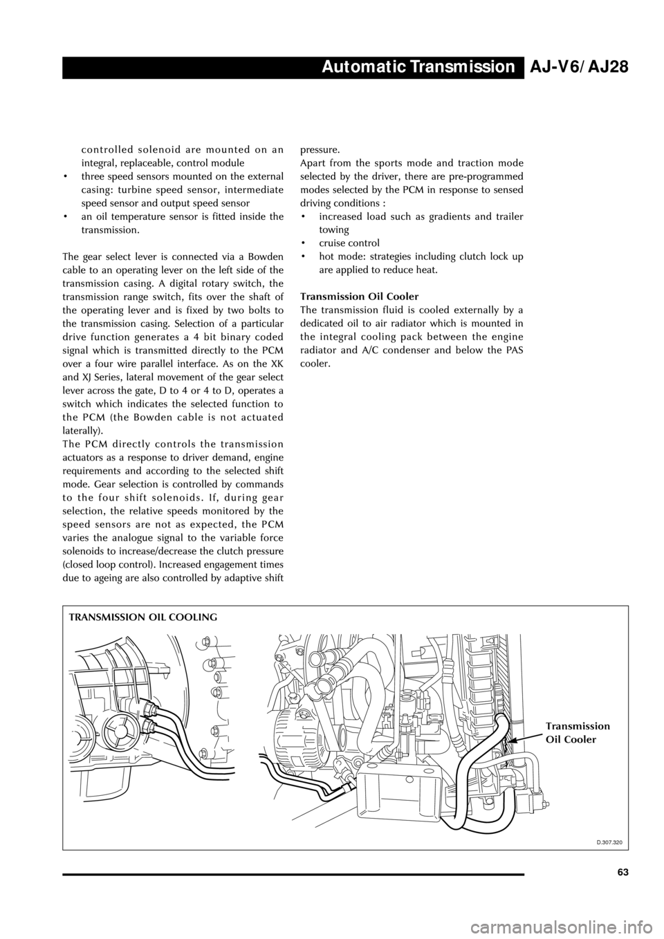
The transmission fluid is cooled externally by a
dedicated oil to air radiator which is mounted in
the integral cooling pack between the engine
radiator and A/C condenser and below the PAS
cooler.
D.307.320
TRANSMISSION OIL COOLING
Transmission
Oil Cooler
D.307.320
Page 70 of 75
Manual TransmissionAJ-V6/AJ28
65
D.307.315
Gear Selector Control
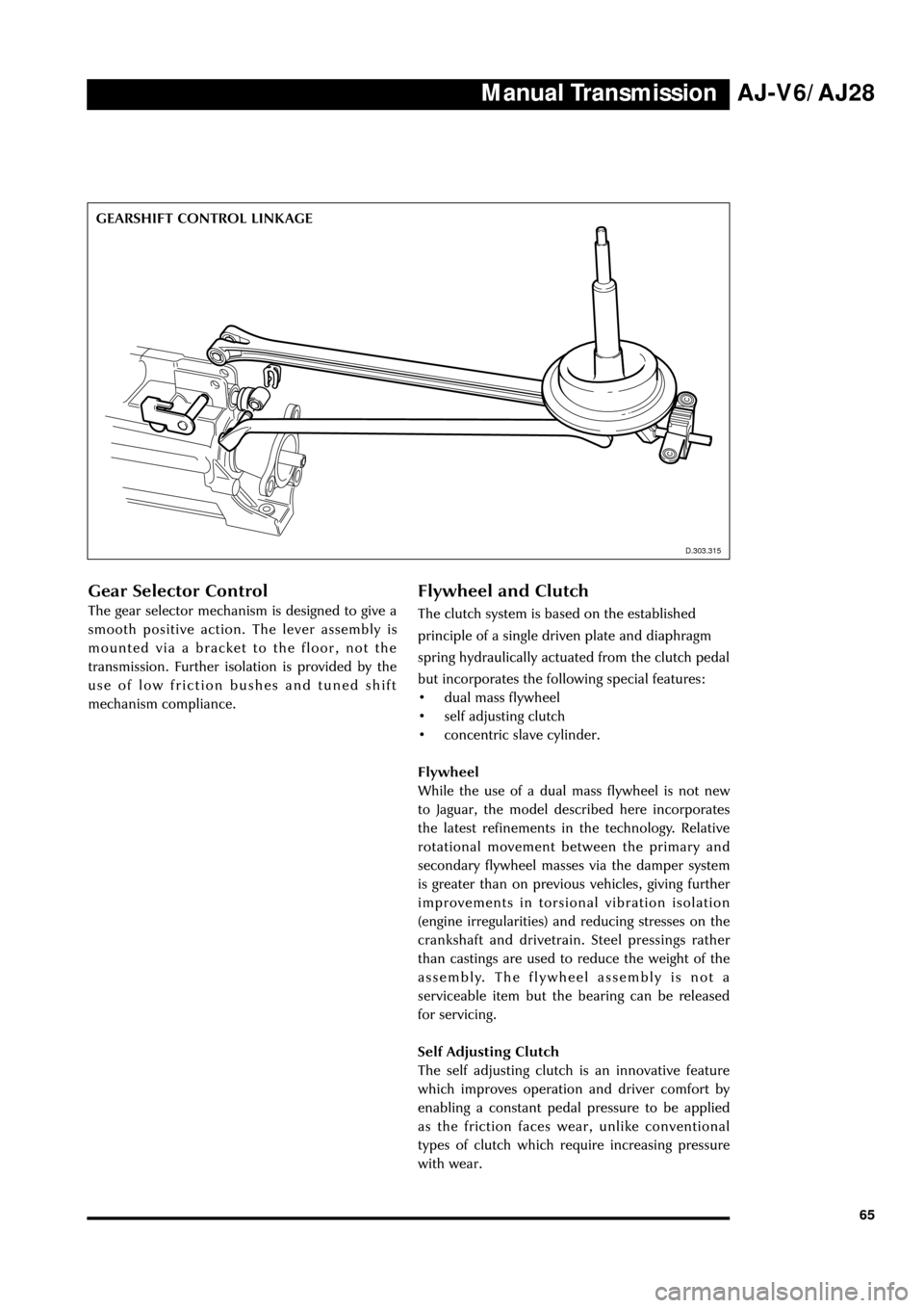
The gear selector mechanism is designed to give a
smooth positive action. The lever assembly is
mounted via a bracket to the floor, not the
transmission. Further isolation is provided by the
use of low friction bushes and tuned shift
mechanism compliance.
Flywheel and Clutch
The clutch system is based on the established
principle of a single driven plate and diaphragm
spring hydraulically actuated from the clutch pedal
but incorporates the following special features:
¥ dual mass flywheel
¥ self adjusting clutch
¥ concentric slave cylinder.
Flywheel
While the use of a dual mass flywheel is not new
to Jaguar, the model described here incorporates
the latest refinements in the technology. Relative
rotational movement between the primary and
secondary flywheel masses via the damper system
is greater than on previous vehicles, giving further
improvements in torsional vibration isolation
(engine irregularities) and reducing stresses on the
crankshaft and drivetrain. Steel pressings rather
than castings are used to reduce the weight of the
assembly. The flywheel assembly is not a
serviceable item but the bearing can be released
for servicing.
Self Adjusting Clutch
The self adjusting clutch is an innovative feature
which improves operation and driver comfort by
enabling a constant pedal pressure to be applied
as the friction faces wear, unlike conventional
types of clutch which require increasing pressure
with wear. GEARSHIFT CONTROL LINKAGE
D.303.315
Page 71 of 75
Manual Transmission AJ-V6/AJ28
66With a conventional clutch, increased lining wear
causes the angle of the actuating diaphragm
spring to change as the pressure plate moves
axially towards the engine, requiring a greater
force to operate the clutch (diaphragm actuating
force varies with diaphragm angle). The self
adjusting clutch eliminates the problem by
allowing the diaphragm spring to follow the axial
movement of the pressure plate thus maintaining
the diaphragm spring at the same angle
throughout the life of the clutch. As well as
maintaining a constant pedal pressure, the clamp
force on the pressure plate also remains constant
with wear.
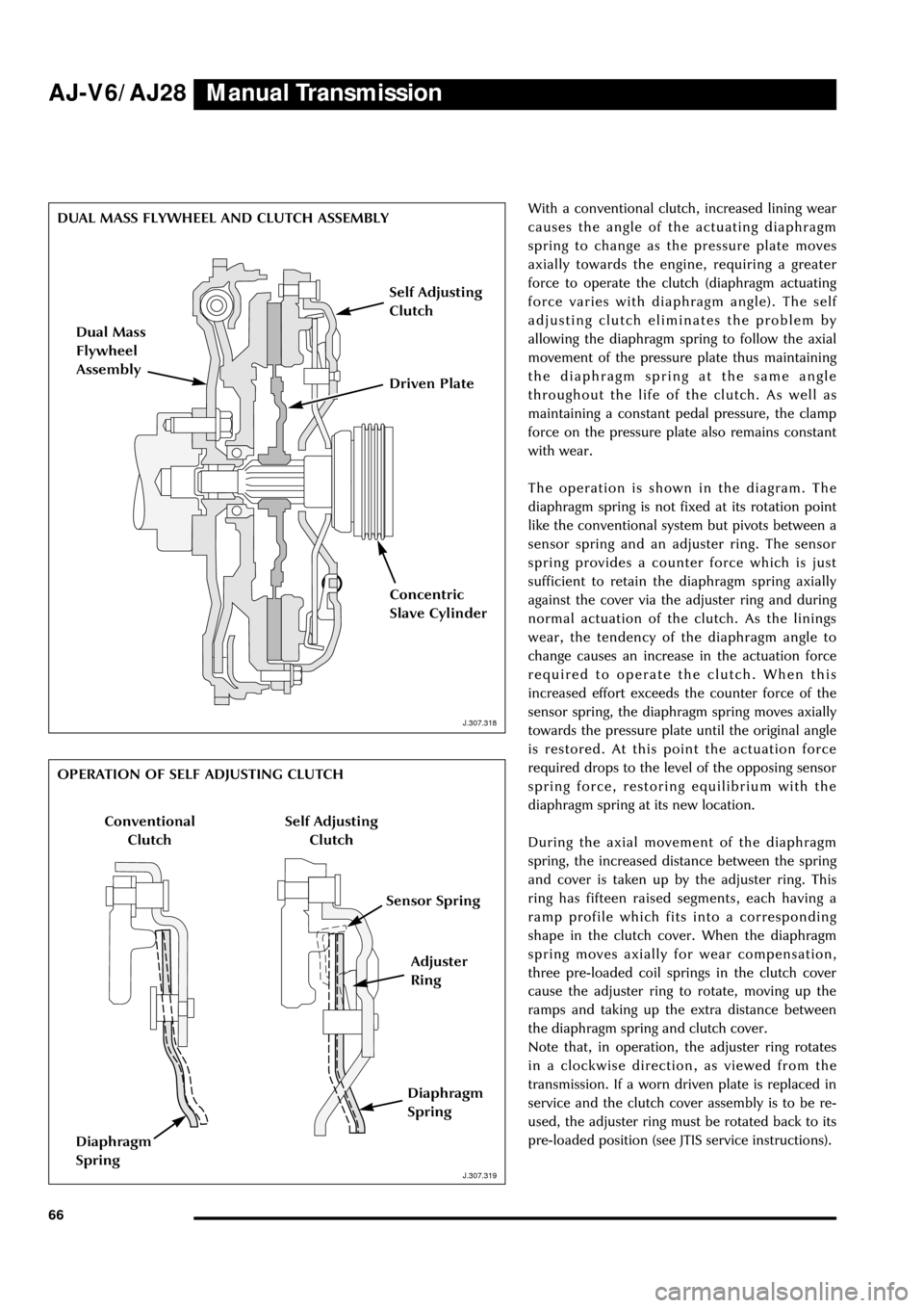
The operation is shown in the diagram. The
diaphragm spring is not fixed at its rotation point
like the conventional system but pivots between a
sensor spring and an adjuster ring. The sensor
spring provides a counter force which is just
sufficient to retain the diaphragm spring axially
against the cover via the adjuster ring and during
normal actuation of the clutch. As the linings
wear, the tendency of the diaphragm angle to
change causes an increase in the actuation force
required to operate the clutch. When this
increased effort exceeds the counter force of the
sensor spring, the diaphragm spring moves axially
towards the pressure plate until the original angle
is restored. At this point the actuation force
required drops to the level of the opposing sensor
spring force, restoring equilibrium with the
diaphragm spring at its new location.
During the axial movement of the diaphragm
spring, the increased distance between the spring
and cover is taken up by the adjuster ring. This
ring has fifteen raised segments, each having a
ramp profile which fits into a corresponding
shape in the clutch cover. When the diaphragm
spring moves axially for wear compensation,
three pre-loaded coil springs in the clutch cover
cause the adjuster ring to rotate, moving up the
ramps and taking up the extra distance between
the diaphragm spring and clutch cover.
Note that, in operation, the adjuster ring rotates
in a clockwise direction, as viewed from the
transmission. If a worn driven plate is replaced in
service and the clutch cover assembly is to be re-
used, the adjuster ring must be rotated back to its
pre-loaded position (see JTIS service instructions).
J.307.318
DUAL MASS FLYWHEEL AND CLUTCH ASSEMBLY
J.307.318
J.307.319
OPERATION OF SELF ADJUSTING CLUTCH
J.307.319
Dual Mass
Flywheel
Assembly
Self Adjusting
Clutch
Driven Plate
Concentric
Slave Cylinder
Adjuster
Ring
Conventional
Clutch
Sensor Spring
Diaphragm
Spring
Self Adjusting
Clutch
Diaphragm
Spring
Page 74 of 75
Powertrain ManagementAJ-V6/AJ28
69
Introduction
All powertrain and associated management
functions are controlled from a single unit, the
powertrain control module (PCM). These
functions are as follows:
¥ overall monitoring and control of
performance, fuel economy, emissions,
driveability and safety
¥ receives and processes direct inputs from
engine, transmission, fuel system and
ancillary systems sensors
¥ provides direct control of actuator devices
¥ communicates with other modules via the
SCP bus (eg to obtain wheel speed
information)
¥ provides system diagnostics to conform to
OBDII requirements.
Powertrain Control Module (PCM)
The basic PCM is common to the V6 and V8
engines but with unique programming to suit the
respective engine characteristics and some
differences in the interface circuits for the
different sensors and actuators.
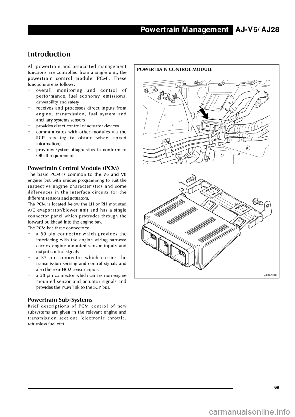
The PCM is located below the LH or RH mounted
A/C evaporator/blower unit and has a single
connector panel which protrudes through the
forward bulkhead into the engine bay.
The PCM has three connectors:
¥ a 60 pin connector which provides the
interfacing with the engine wiring harness:
carries engine mounted sensor inputs and
output control signals
¥ a 32 pin connector which carries the
transmission sensing and control signals and
also the rear HO2 sensor inputs
¥ a 58 pin connector which carries non engine
mounted sensor and actuator signals and
provides the PCM link to the SCP bus.
Powertrain Sub-Systems
Brief descriptions of PCM control of new
subsystems are given in the relevant engine and
transmission sections (electronic throttle,
returnless fuel etc).
J.303.1393
POWERTRAIN CONTROL MODULE
J.303.1393