diagram JAGUAR S TYPE 1999 1.G Powertrain Manual
[x] Cancel search | Manufacturer: JAGUAR, Model Year: 1999, Model line: S TYPE, Model: JAGUAR S TYPE 1999 1.GPages: 75, PDF Size: 3.4 MB
Page 24 of 75

V6 EngineAJ-V6/AJ28
19
Variable Valve Timing (VVT)
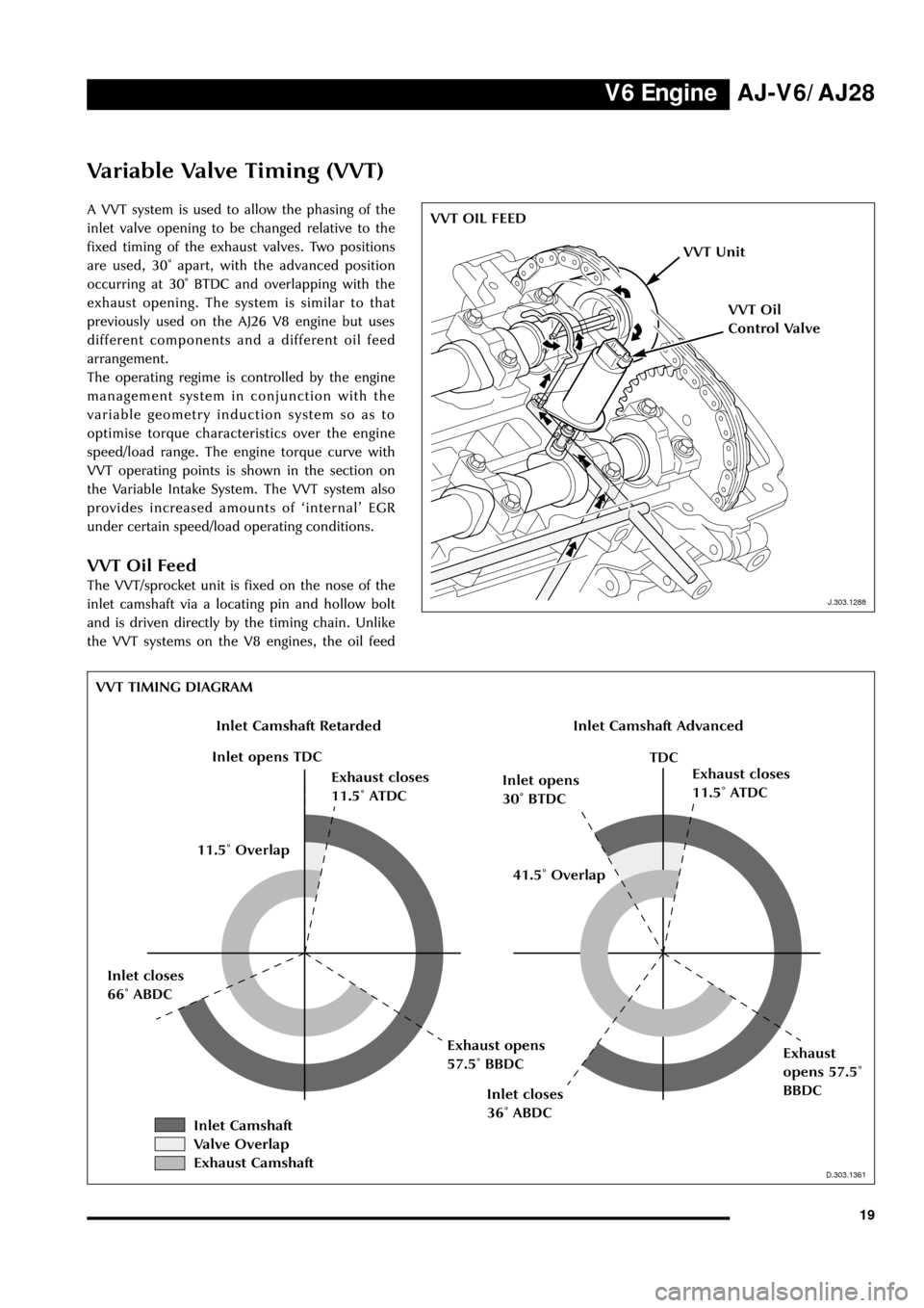
A VVT system is used to allow the phasing of the
inlet valve opening to be changed relative to the
fixed timing of the exhaust valves. Two positions
are used, 30û apart, with the advanced position
occurring at 30û BTDC and overlapping with the
exhaust opening. The system is similar to that
previously used on the AJ26 V8 engine but uses
different components and a different oil feed
arrangement.
The operating regime is controlled by the engine
management system in conjunction with the
variable geometry induction system so as to
optimise torque characteristics over the engine
speed/load range. The engine torque curve with
VVT operating points is shown in the section on
the Variable Intake System. The VVT system also
provides increased amounts of ÔinternalÕ EGR
under certain speed/load operating conditions.
VVT Oil Feed
The VVT/sprocket unit is fixed on the nose of the
inlet camshaft via a locating pin and hollow bolt
and is driven directly by the timing chain. Unlike
the VVT systems on the V8 engines, the oil feed
J.303.1288
VVT OIL FEED
J.303.1288
VVT Unit
VVT Oil
Control Valve
D.303.1361
VVT TIMING DIAGRAM
D.303.1361
Inlet Camshaft RetardedInlet Camshaft Advanced
Inlet opens TDC
Exhaust closes
11.5û ATDCInlet opens
30û BTDCExhaust closes
11.5û ATDC
TDC
Inlet closes
36û ABDC
Exhaust
opens 57.5û
BBDC Inlet closes
66û ABDCExhaust opens
57.5û BBDC41.5û Overlap 11.5û Overlap
Inlet Camshaft
Valve Overlap
Exhaust Camshaft
Page 71 of 75

Manual Transmission AJ-V6/AJ28
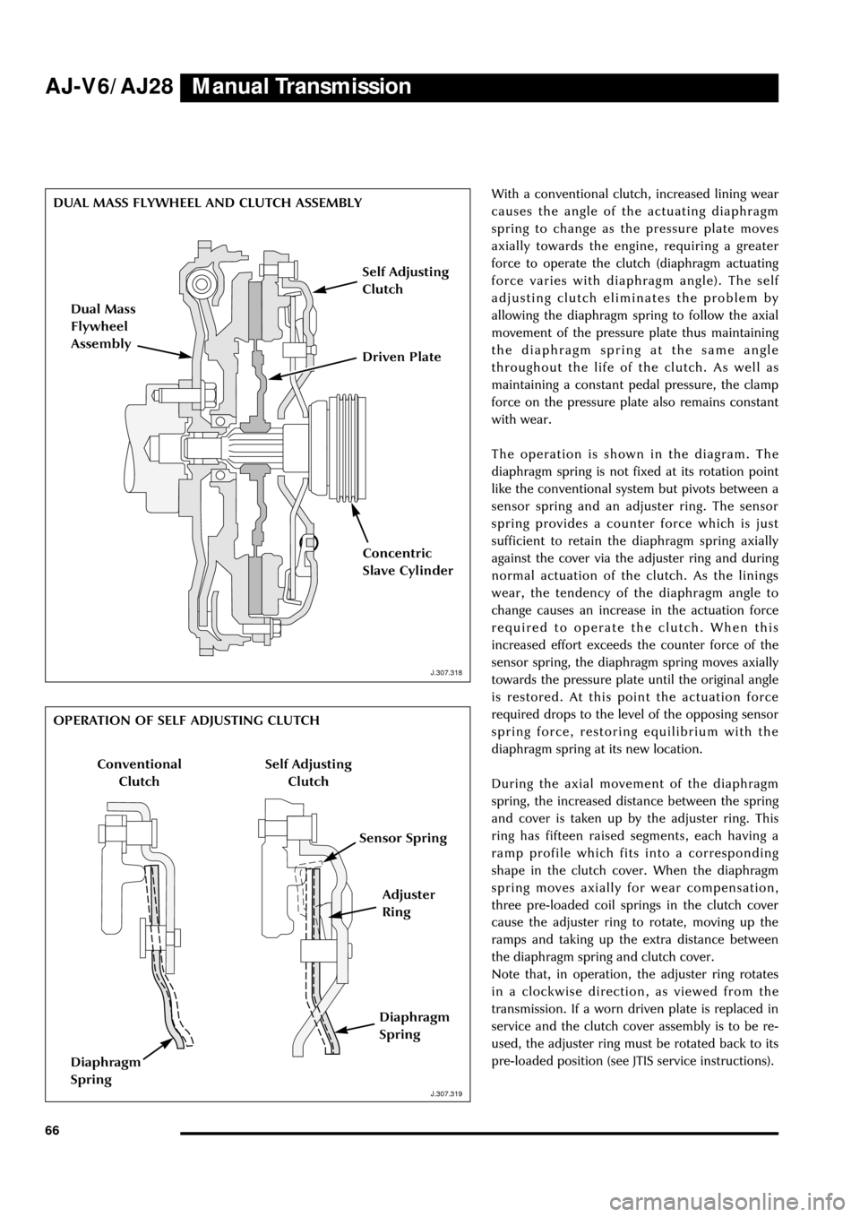
66With a conventional clutch, increased lining wear
causes the angle of the actuating diaphragm
spring to change as the pressure plate moves
axially towards the engine, requiring a greater
force to operate the clutch (diaphragm actuating
force varies with diaphragm angle). The self
adjusting clutch eliminates the problem by
allowing the diaphragm spring to follow the axial
movement of the pressure plate thus maintaining
the diaphragm spring at the same angle
throughout the life of the clutch. As well as
maintaining a constant pedal pressure, the clamp
force on the pressure plate also remains constant
with wear.
The operation is shown in the diagram. The
diaphragm spring is not fixed at its rotation point
like the conventional system but pivots between a
sensor spring and an adjuster ring. The sensor
spring provides a counter force which is just
sufficient to retain the diaphragm spring axially
against the cover via the adjuster ring and during
normal actuation of the clutch. As the linings
wear, the tendency of the diaphragm angle to
change causes an increase in the actuation force
required to operate the clutch. When this
increased effort exceeds the counter force of the
sensor spring, the diaphragm spring moves axially
towards the pressure plate until the original angle
is restored. At this point the actuation force
required drops to the level of the opposing sensor
spring force, restoring equilibrium with the
diaphragm spring at its new location.
During the axial movement of the diaphragm
spring, the increased distance between the spring
and cover is taken up by the adjuster ring. This
ring has fifteen raised segments, each having a
ramp profile which fits into a corresponding
shape in the clutch cover. When the diaphragm
spring moves axially for wear compensation,
three pre-loaded coil springs in the clutch cover
cause the adjuster ring to rotate, moving up the
ramps and taking up the extra distance between
the diaphragm spring and clutch cover.
Note that, in operation, the adjuster ring rotates
in a clockwise direction, as viewed from the
transmission. If a worn driven plate is replaced in
service and the clutch cover assembly is to be re-
used, the adjuster ring must be rotated back to its
pre-loaded position (see JTIS service instructions).
J.307.318
DUAL MASS FLYWHEEL AND CLUTCH ASSEMBLY
J.307.318
J.307.319
OPERATION OF SELF ADJUSTING CLUTCH
J.307.319
Dual Mass
Flywheel
Assembly
Self Adjusting
Clutch
Driven Plate
Concentric
Slave Cylinder
Adjuster
Ring
Conventional
Clutch
Sensor Spring
Diaphragm
Spring
Self Adjusting
Clutch
Diaphragm
Spring