differential JAGUAR S TYPE 1999 1.G Powertrain Manual
[x] Cancel search | Manufacturer: JAGUAR, Model Year: 1999, Model line: S TYPE, Model: JAGUAR S TYPE 1999 1.GPages: 75, PDF Size: 3.4 MB
Page 22 of 75

V6 EngineAJ-V6/AJ28
17
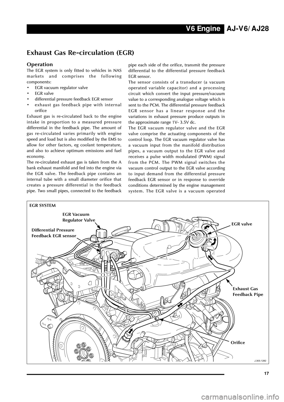
Exhaust Gas Re-circulation (EGR)
Operation
The EGR system is only fitted to vehicles in NAS
markets and comprises the following
components:
¥ EGR vacuum regulator valve
¥ EGR valve
¥ differential pressure feedback EGR sensor
¥ exhaust gas feedback pipe with internal
orifice
Exhaust gas is re-circulated back to the engine
intake in proportion to a measured pressure
differential in the feedback pipe. The amount of
gas re-circulated varies primarily with engine
speed and load but is also modified by the EMS to
allow for other factors, eg coolant temperature,
and also to achieve optimum emissions and fuel
economy.
The re-circulated exhaust gas is taken from the A
bank exhaust manifold and fed into the engine via
the EGR valve. The feedback pipe contains an
internal tube with a small diameter orifice that
creates a pressure differential in the feedback
pipe. Two small pipes, connected to the feedbackpipe each side of the orifice, transmit the pressure
differential to the differential pressure feedback
EGR sensor.
The sensor consists of a transducer (a vacuum
operated variable capacitor) and a processing
circuit which convert the input pressure/vacuum
value to a corresponding analogue voltage which is
sent to the PCM. The differential pressure feedback
EGR sensor has a linear response and the
variations in exhaust pressure produce outputs in
the approximate range 1V- 3.5V dc.
The EGR vacuum regulator valve and the EGR
valve comprise the actuating components of the
control loop. The EGR vacuum regulator valve has
a vacuum input from the manifold distribution
pipes, a vacuum output to the EGR valve and
receives a pulse width modulated (PWM) signal
from the PCM. The PWM signal switches the
vacuum control output to the EGR valve according
to input demand from the differential pressure
feedback EGR sensor or in response to override
conditions determined by the engine management
system. The EGR valve is a vacuum operated
EGR SYSTEM
J.303.1282
Exhaust Gas
Feedback Pipe
Differential Pressure
Feedback EGR sensor
EGR Vacuum
Regulator Valve
EGR valve
Orifice
Page 23 of 75

V6 Engine AJ-V6/AJ28
18diaphragm valve with no electrical connections
which opens the EGR feed pipe to the induction
manifold under the EGR vacuum regulator
control.
Where the EGR system is not fitted, a blanking
plate seals the manifold in place of the EGR valve.
Control Conditions
EGR operates over most of the engine speed/load
range but is disabled by the engine management
system under certain conditions:
¥ during engine cranking
¥ until normal operating temperature is
reached
¥ when the diagnostic system registers a failure
which affects the EGR system (eg a faulty
sensor)
¥ during idling to avoid unstable or erratic
running
¥ during wide open throttle operation
¥ when traction control is operative.
While the main control loop is based on feedback
from the differential pressure feedback EGR
sensor, the EGR rate is also modified by other
engine conditions; coolant, ambient and air
charge temperatures, barometric pressure, VVT
cam position and air charge mass. Note also that
the EGR rate increases gradually after it is enabled
on each drive cycle.
Page 34 of 75

V6 EngineAJ-V6/AJ28
29
D.303.1215
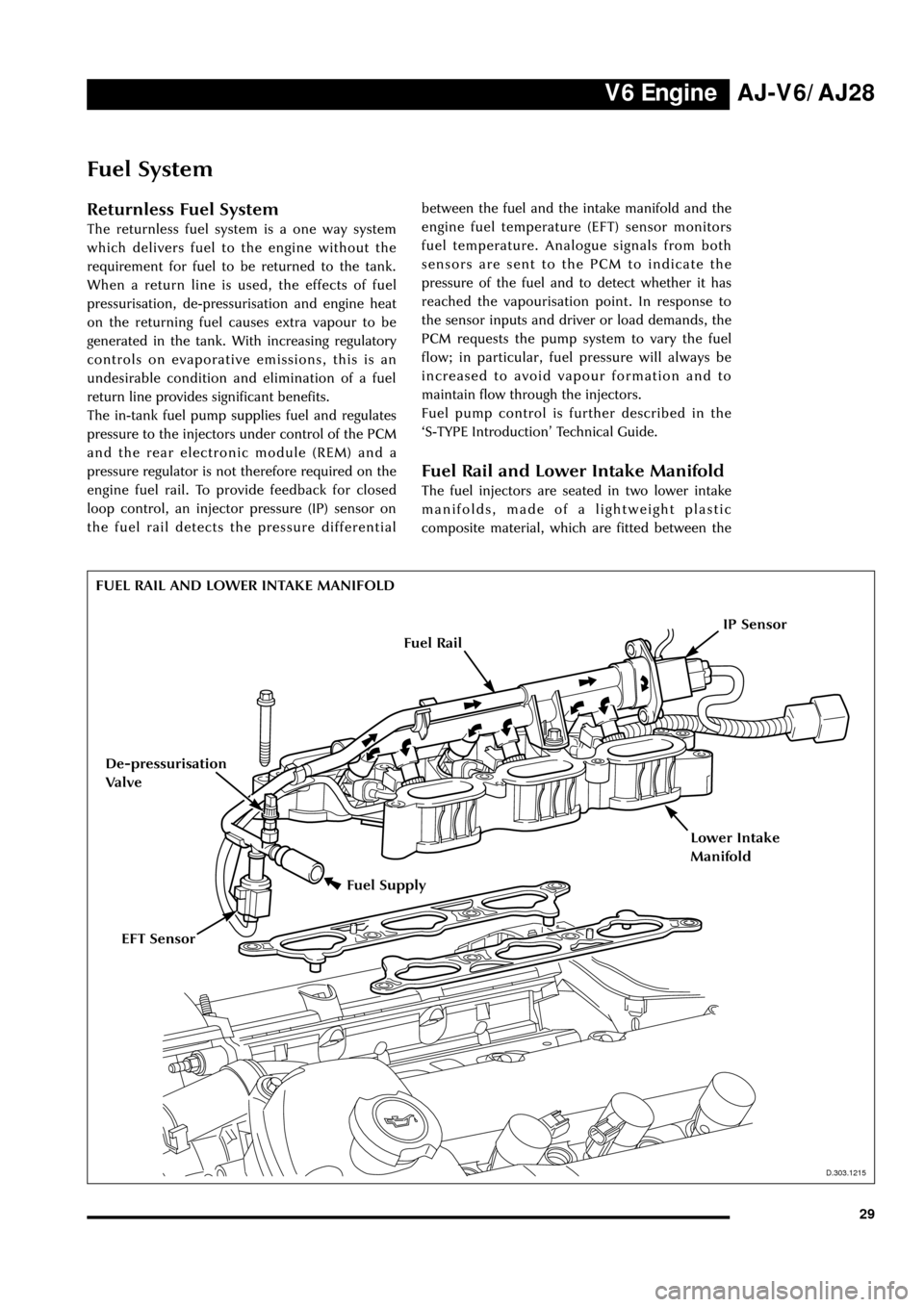
FUEL RAIL AND LOWER INTAKE MANIFOLD
Fuel Supply
D.303.1215
EFT Sensor
De-pressurisation
Valve
IP Sensor
Fuel System
Returnless Fuel System
The returnless fuel system is a one way system
which delivers fuel to the engine without the
requirement for fuel to be returned to the tank.
When a return line is used, the effects of fuel
pressurisation, de-pressurisation and engine heat
on the returning fuel causes extra vapour to be
generated in the tank. With increasing regulatory
controls on evaporative emissions, this is an
undesirable condition and elimination of a fuel
return line provides significant benefits.
The in-tank fuel pump supplies fuel and regulates
pressure to the injectors under control of the PCM
and the rear electronic module (REM) and a
pressure regulator is not therefore required on the
engine fuel rail. To provide feedback for closed
loop control, an injector pressure (IP) sensor on
the fuel rail detects the pressure differentialbetween the fuel and the intake manifold and the
engine fuel temperature (EFT) sensor monitors
fuel temperature. Analogue signals from both
sensors are sent to the PCM to indicate the
pressure of the fuel and to detect whether it has
reached the vapourisation point. In response to
the sensor inputs and driver or load demands, the
PCM requests the pump system to vary the fuel
flow; in particular, fuel pressure will always be
increased to avoid vapour formation and to
maintain flow through the injectors.
Fuel pump control is further described in the
ÔS-TYPE IntroductionÕ Technical Guide.
Fuel Rail and Lower Intake Manifold
The fuel injectors are seated in two lower intake
manifolds, made of a lightweight plastic
composite material, which are fitted between the
Fuel Rail
Lower Intake
Manifold
Page 36 of 75

V6 EngineAJ-V6/AJ28
31
J.303.1365
Engine Cooling
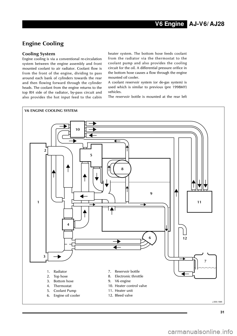
Cooling System
Engine cooling is via a conventional re-circulation
system between the engine assembly and front
mounted coolant to air radiator. Coolant flow is
from the front of the engine, dividing to pass
around each bank of cylinders towards the rear
and then flowing forward through the cylinder
heads. The coolant from the engine returns to the
top RH side of the radiator, by-pass circuit and
also provides the hot input feed to the cabin
V6 ENGINE COOLING SYSTEMheater system. The bottom hose feeds coolant
from the radiator via the thermostat to the
coolant pump and also provides the cooling
circuit for the oil. A differential pressure orifice in
the bottom hose causes a flow through the engine
mounted oil cooler.
A coolant reservoir system (or de-gas system) is
used which is similar to previous (pre 1998MY)
vehicles.
The reservoir bottle is mounted at the rear left
1. Radiator
2. Top hose
3. Bottom hose
4. Thermostat
5. Coolant Pump
6. Engine oil cooler7. Reservoir bottle
8. Electronic throttle
9. V6 engine
10. Heater control valve
11. Heater unit
12. Bleed valve
1
10
5
11
9
4
6
2
3
8
12
7
J.303.1365