width JAGUAR S TYPE 1999 1.G Powertrain Manual
[x] Cancel search | Manufacturer: JAGUAR, Model Year: 1999, Model line: S TYPE, Model: JAGUAR S TYPE 1999 1.GPages: 75, PDF Size: 3.4 MB
Page 7 of 75

Glossary
2The following abbreviations are used in this document:
A Ab
bb
br
re
ev
vi
ia
at
ti
io
on
nD
De
es
sc
cr
ri
ip
pt
ti
io
on
n
AAC air assisted (injection) control valve
AAI air assisted injection
ABDC after bottom dead centre
A/C air conditioning
AH amp-hour
API American Petroleum Institute
APP accelerator pedal position (sensor)
ATDC after top dead centre
bank 1 A bank
bank 2 B bank
BBDC before bottom dead centre
BTDC before top dead centre
ûC degree Celsius
CHT cylinder head temperature (sensor)
CKP crankshaft position (sensor)
CMP camshaft position (sensor)
ECT engine coolant temperature (sensor)
EFT engine fuel temperature (sensor)
EGR exhaust gas recirculation
EMS engine management system
EOP engine oil pressure (sensor)
EOT engine oil temperature (sensor)
EVAP evaporative emission
ûF degrees Fahrenheit
HO2 heated oxygen (sensor)
Hz Hertz (cycles per second)
IAT intake air temperature (sensor)
IMT intake manifold tuning (valve)
IP injector pressure (sensor)
JTIS Jaguar Technical Information System
KS knock sensor (sensor)
LH lefthand
MAF mass air flow (sensor)
N/A normally aspirated
NAS North American specification
OBDII on-board diagnostics stage 2
PAS power assisted steering
PCM powertrain control module
PCV positive crankcase ventilation
PWM pulse width modulated
RH righthand
RPM revolutions per minute
SAE Society of Automotive Engineers (USA)
SCP standard corporate protocol
TAC throttle actuator control (module)
TP throttle position (sensor)
VVT variable valve timing
W watts
AJ-V6/AJ28
Page 22 of 75

V6 EngineAJ-V6/AJ28
17
Exhaust Gas Re-circulation (EGR)
Operation
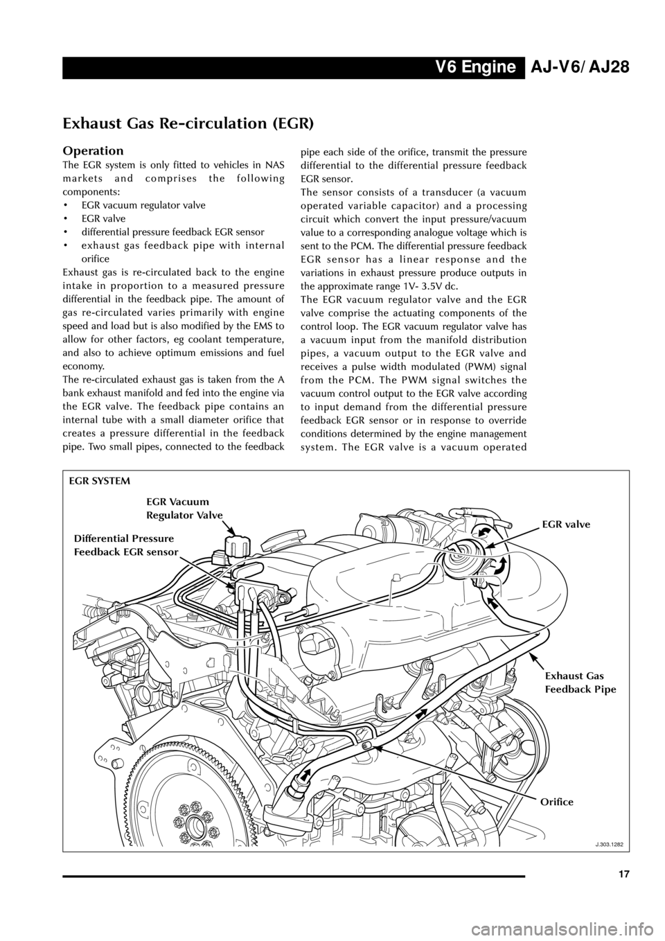
The EGR system is only fitted to vehicles in NAS
markets and comprises the following
components:
¥ EGR vacuum regulator valve
¥ EGR valve
¥ differential pressure feedback EGR sensor
¥ exhaust gas feedback pipe with internal
orifice
Exhaust gas is re-circulated back to the engine
intake in proportion to a measured pressure
differential in the feedback pipe. The amount of
gas re-circulated varies primarily with engine
speed and load but is also modified by the EMS to
allow for other factors, eg coolant temperature,
and also to achieve optimum emissions and fuel
economy.
The re-circulated exhaust gas is taken from the A
bank exhaust manifold and fed into the engine via
the EGR valve. The feedback pipe contains an
internal tube with a small diameter orifice that
creates a pressure differential in the feedback
pipe. Two small pipes, connected to the feedbackpipe each side of the orifice, transmit the pressure
differential to the differential pressure feedback
EGR sensor.
The sensor consists of a transducer (a vacuum
operated variable capacitor) and a processing
circuit which convert the input pressure/vacuum
value to a corresponding analogue voltage which is
sent to the PCM. The differential pressure feedback
EGR sensor has a linear response and the
variations in exhaust pressure produce outputs in
the approximate range 1V- 3.5V dc.
The EGR vacuum regulator valve and the EGR
valve comprise the actuating components of the
control loop. The EGR vacuum regulator valve has
a vacuum input from the manifold distribution
pipes, a vacuum output to the EGR valve and
receives a pulse width modulated (PWM) signal
from the PCM. The PWM signal switches the
vacuum control output to the EGR valve according
to input demand from the differential pressure
feedback EGR sensor or in response to override
conditions determined by the engine management
system. The EGR valve is a vacuum operated
EGR SYSTEM
J.303.1282
Exhaust Gas
Feedback Pipe
Differential Pressure
Feedback EGR sensor
EGR Vacuum
Regulator Valve
EGR valve
Orifice
Page 32 of 75

V6 EngineAJ-V6/AJ28
27
D.418.428
APP Sensor
303-050
APP SENSORAccelerator Pedal Position (APP)
Sensor
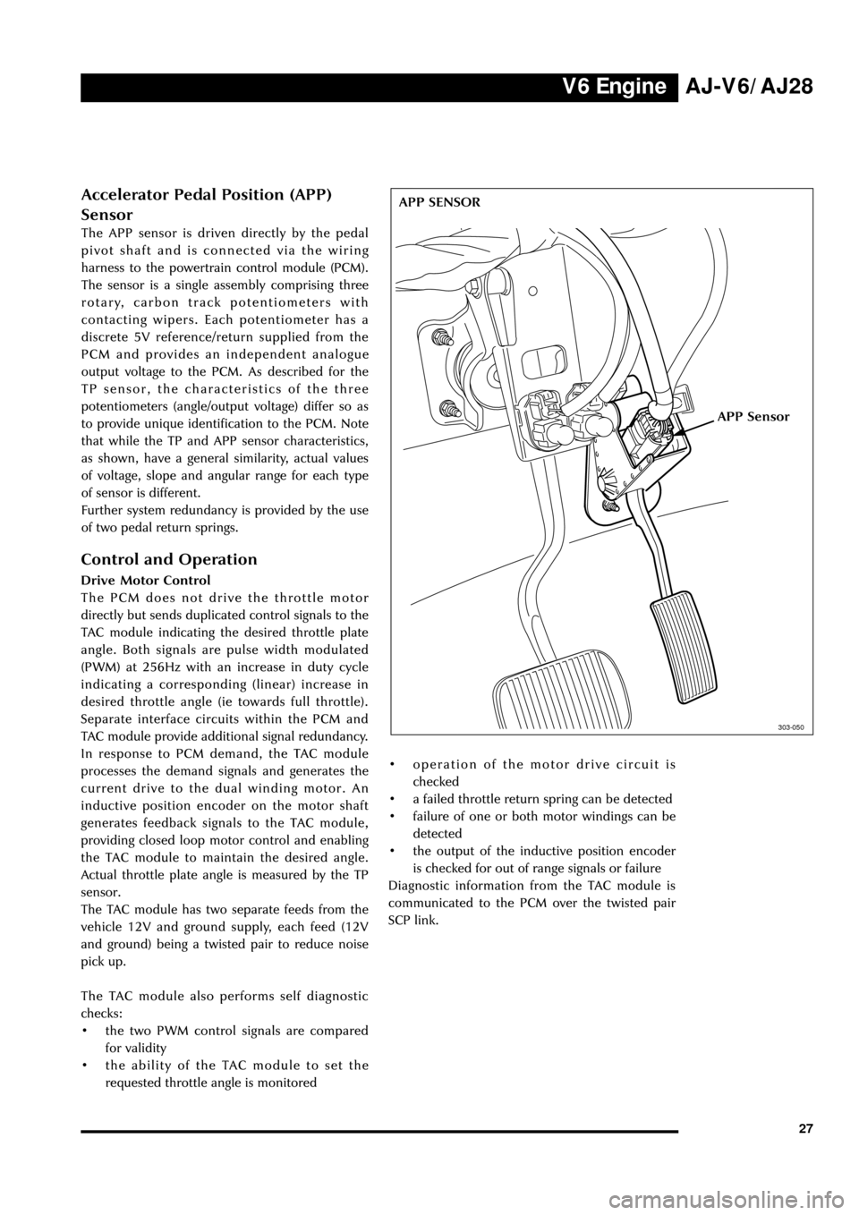
The APP sensor is driven directly by the pedal
pivot shaft and is connected via the wiring
harness to the powertrain control module (PCM).
The sensor is a single assembly comprising three
rotary, carbon track potentiometers with
contacting wipers. Each potentiometer has a
discrete 5V reference/return supplied from the
PCM and provides an independent analogue
output voltage to the PCM. As described for the
TP sensor, the characteristics of the three
potentiometers (angle/output voltage) differ so as
to provide unique identification to the PCM. Note
that while the TP and APP sensor characteristics,
as shown, have a general similarity, actual values
of voltage, slope and angular range for each type
of sensor is different.
Further system redundancy is provided by the use
of two pedal return springs.
Control and Operation
Drive Motor Control
The PCM does not drive the throttle motor
directly but sends duplicated control signals to the
TAC module indicating the desired throttle plate
angle. Both signals are pulse width modulated
(PWM) at 256Hz with an increase in duty cycle
indicating a corresponding (linear) increase in
desired throttle angle (ie towards full throttle).
Separate interface circuits within the PCM and
TAC module provide additional signal redundancy.
In response to PCM demand, the TAC module
processes the demand signals and generates the
current drive to the dual winding motor. An
inductive position encoder on the motor shaft
generates feedback signals to the TAC module,
providing closed loop motor control and enabling
the TAC module to maintain the desired angle.
Actual throttle plate angle is measured by the TP
sensor.
The TAC module has two separate feeds from the
vehicle 12V and ground supply, each feed (12V
and ground) being a twisted pair to reduce noise
pick up.
The TAC module also performs self diagnostic
checks:
¥ the two PWM control signals are compared
for validity
¥ the ability of the TAC module to set the
requested throttle angle is monitored¥ operation of the motor drive circuit is
checked
¥ a failed throttle return spring can be detected
¥ failure of one or both motor windings can be
detected
¥ the output of the inductive position encoder
is checked for out of range signals or failure
Diagnostic information from the TAC module is
communicated to the PCM over the twisted pair
SCP link.