ignition JAGUAR S TYPE 2005 1.G Technical Guide Update
[x] Cancel search | Manufacturer: JAGUAR, Model Year: 2005, Model line: S TYPE, Model: JAGUAR S TYPE 2005 1.GPages: 133, PDF Size: 3.48 MB
Page 30 of 133
JAGUARS-TYPEBody
25
Fascia
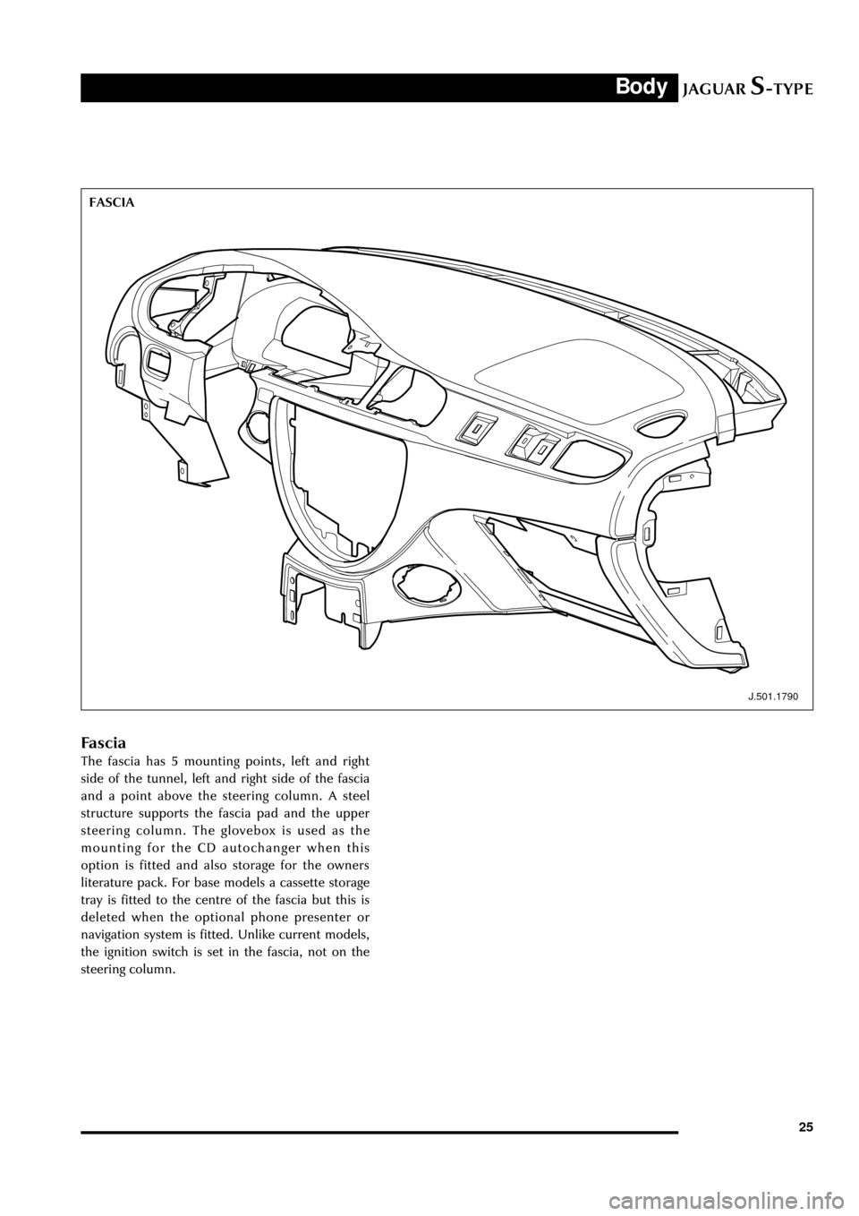
The fascia has 5 mounting points, left and right
side of the tunnel, left and right side of the fascia
and a point above the steering column. A steel
structure supports the fascia pad and the upper
steering column. The glovebox is used as the
mounting for the CD autochanger when this
option is fitted and also storage for the owners
literature pack. For base models a cassette storage
tray is fitted to the centre of the fascia but this is
deleted when the optional phone presenter or
navigation system is fitted. Unlike current models,
the ignition switch is set in the fascia, not on the
steering column.
J.501.1790
FASCIA
Page 33 of 133
JAGUARS-TYPEBody
28bracket for the airbag. The recline motor is located
in the lower left side of the frame and drives both
sides of the squab. The position potentiometer is
mounted on the long drive shaft on the RH side.
Lumbar support comprises a flexible steel lumbar
plate, motor, drive cable and return spring. The
top of the plate has vertical slots, fitted to a cross
bar, which allows the plate to be pulled down and
deformed by the drive cable to provide increased
lumbar support. If powered lumbar support is not
fitted, the lumbar plate is used without the drive
system.
When seat heaters are fitted each front seat has a
driver or passenger seat heater control module
fitted (DSHCM/PSHCM).
Seat Covers
The cushion and squab cover are made of dual
density foam and have optional heater pad inserts.
The cushion and cushion pan have an anti-
submarining profile for increased safety.
J.501.1786
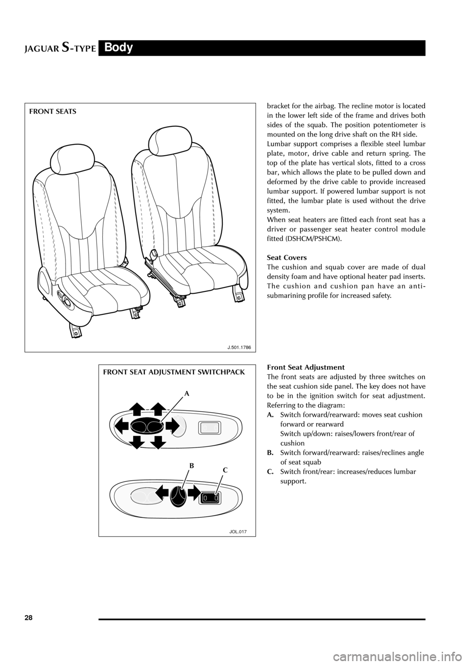
Front Seat Adjustment
The front seats are adjusted by three switches on
the seat cushion side panel. The key does not have
to be in the ignition switch for seat adjustment.
Referring to the diagram:
A.Switch forward/rearward: moves seat cushion
forward or rearward
Switch up/down: raises/lowers front/rear of
cushion
B.Switch forward/rearward: raises/reclines angle
of seat squab
C.Switch front/rear: increases/reduces lumbar
support.
JOL.017
FRONT SEAT ADJUSTMENT SWITCHPACK
A
B FRONT SEATS
C
Page 42 of 133
JAGUARS-TYPEOccupant Protection
37
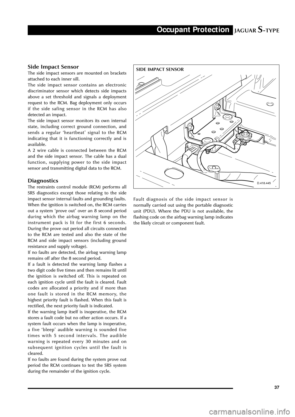
D.418.445
SIDE IMPACT SENSORSide Impact Sensor
The side impact sensors are mounted on brackets
attached to each inner sill.
The side impact sensor contains an electronic
discriminator sensor which detects side impacts
above a set threshold and signals a deployment
request to the RCM. Bag deployment only occurs
if the side safing sensor in the RCM has also
detected an impact.
The side impact sensor monitors its own internal
state, including correct ground connection, and
sends a regular ÔheartbeatÕ signal to the RCM
indicating that it is functioning correctly and is
available.
A 2 wire cable is connected between the RCM
and the side impact sensor. The cable has a dual
function, supplying power to the side impact
sensor and transmitting digital data to the RCM.
Diagnostics
The restraints control module (RCM) performs all
SRS diagnostics except those relating to the side
impact sensor internal faults and grounding faults.
When the ignition is switched on, the RCM carries
out a system Ôprove outÕ over an 8 second period
during which the airbag warning lamp on the
instrument pack is lit for the first 6 seconds.
During the prove out period all circuits connected
to the RCM are tested and also the state of the
RCM and side impact sensors (including ground
resistance and supply voltage).
If no faults are detected, the airbag warning lamp
remains off after the 8 second period.
If a fault is detected the warning lamp flashes a
two digit code five times and then remains lit until
the ignition is switched off. This is repeated on
each ignition cycle until the fault is cleared. Fault
codes are allocated a priority and if more than
one fault is stored in the RCM memory, the
highest priority fault is flashed. When this fault is
rectified, the next priority fault is indicated.
If the warning lamp itself is inoperative, the RCM
stores a fault code but no other action occurs. If a
system fault occurs when the lamp is inoperative,
a five ÔbleepÕ audible warning is sounded five
times with 5 second intervals. The audible
warning is repeated every 30 minutes and on
subsequent ignition cycles until the fault is
cleared.
If no faults are found during the system prove out
period the RCM continues to test the SRS system
during the remainder of the ignition cycle.Fault diagnosis of the side impact sensor is
normally carried out using the portable diagnostic
unit (PDU). Where the PDU is not available, the
flashing code on the airbag warning lamp indicates
the likely circuit or component fault.
Page 46 of 133
JAGUARS-TYPEFuel System
41
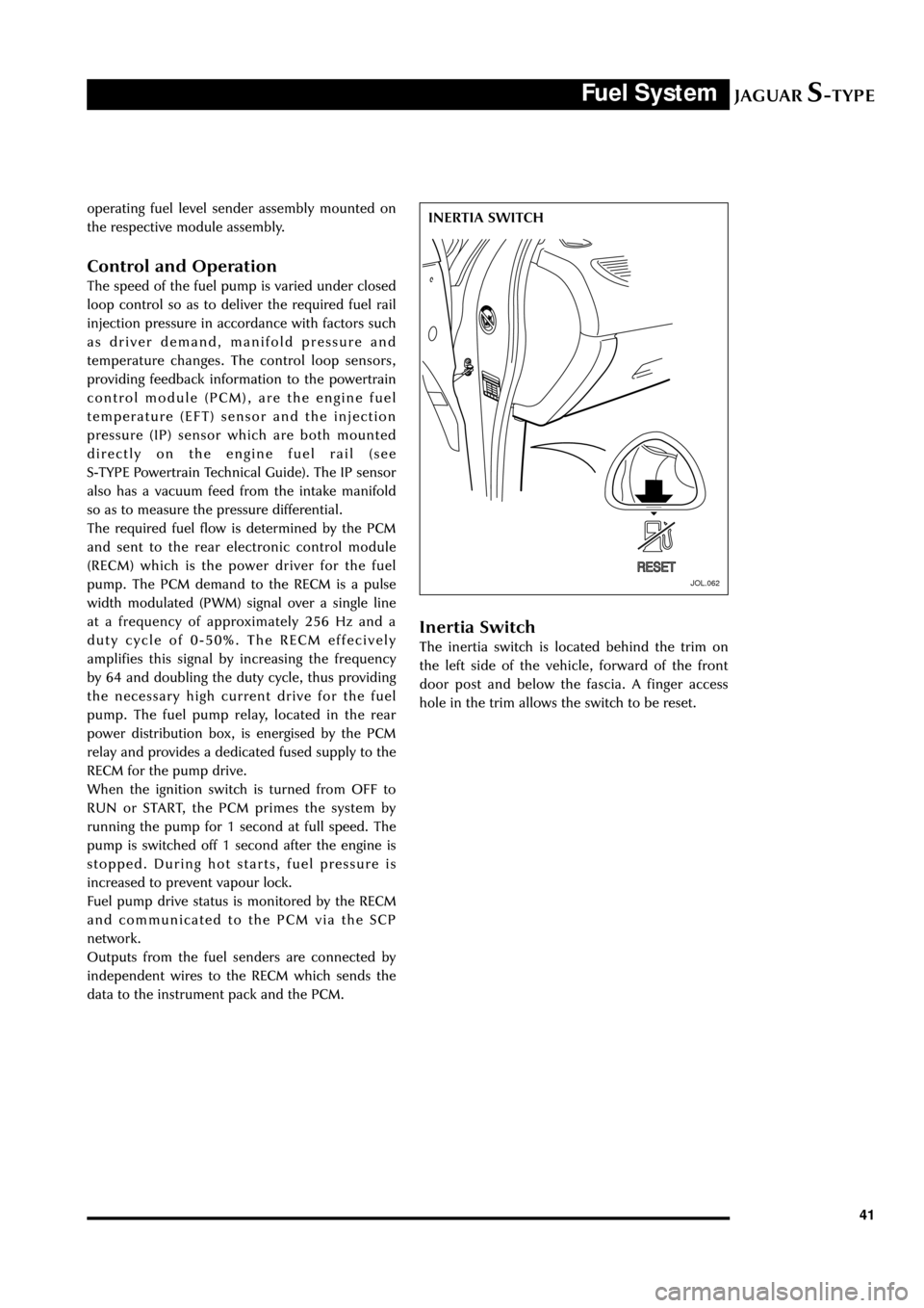
JOL.062
INERTIA SWITCH operating fuel level sender assembly mounted on
the respective module assembly.
Control and Operation
The speed of the fuel pump is varied under closed
loop control so as to deliver the required fuel rail
injection pressure in accordance with factors such
as driver demand, manifold pressure and
temperature changes. The control loop sensors,
providing feedback information to the powertrain
control module (PCM), are the engine fuel
temperature (EFT) sensor and the injection
pressure (IP) sensor which are both mounted
directly on the engine fuel rail (see
S-TYPE Powertrain Technical Guide). The IP sensor
also has a vacuum feed from the intake manifold
so as to measure the pressure differential.
The required fuel flow is determined by the PCM
and sent to the rear electronic control module
(RECM) which is the power driver for the fuel
pump. The PCM demand to the RECM is a pulse
width modulated (PWM) signal over a single line
at a frequency of approximately 256 Hz and a
duty cycle of 0-50%. The RECM effecively
amplifies this signal by increasing the frequency
by 64 and doubling the duty cycle, thus providing
the necessary high current drive for the fuel
pump. The fuel pump relay, located in the rear
power distribution box, is energised by the PCM
relay and provides a dedicated fused supply to the
RECM for the pump drive.
When the ignition switch is turned from OFF to
RUN or START, the PCM primes the system by
running the pump for 1 second at full speed. The
pump is switched off 1 second after the engine is
stopped. During hot starts, fuel pressure is
increased to prevent vapour lock.
Fuel pump drive status is monitored by the RECM
and communicated to the PCM via the SCP
network.
Outputs from the fuel senders are connected by
independent wires to the RECM which sends the
data to the instrument pack and the PCM.
Inertia Switch
The inertia switch is located behind the trim on
the left side of the vehicle, forward of the front
door post and below the fascia. A finger access
hole in the trim allows the switch to be reset.
Page 50 of 133
JAGUARS-TYPETransmission
45
Introduction
The automatic and manual transmission units are
described in the ÔS-TYPE Sports Sedan Powertrain
IntroductionÕ Technical Guide.
J-Gate
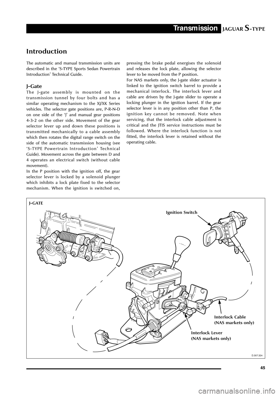
The J-gate assembly is mounted on the
transmission tunnel by four bolts and has a
similar operating mechanism to the XJ/XK Series
vehicles. The selector gate positions are, P-R-N-D
on one side of the ÔJÕ and manual gear positions
4-3-2 on the other side. Movement of the gear
selector lever up and down these positions is
transmitted mechanically to a cable assembly
which then rotates the digital range switch on the
side of the automatic transmission housing (see
ÔS-TYPE Powertrain IntroductionÕ Technical
Guide). Movement across the gate between D and
4 operates an electrical switch (without cable
movement).
In the P position with the ignition off, the gear
selector lever is locked by a solenoid plunger
which inhibits a lock plate fixed to the selector
mechanism. When the ignition is switched on,pressing the brake pedal energises the solenoid
and releases the lock plate, allowing the selector
lever to be moved from the P position.
For NAS markets only, the J-gate slider actuator is
linked to the ignition switch barrel to provide a
mechanical interlock. The interlock lever and
cable are driven by the J-gate slider to operate a
locking plunger in the ignition barrel. If the gear
selector lever is in any position other than P, the
ignition key cannot be removed. Note when
servicing, that the interlock cable adjustment is
critical and the JTIS service instructions must be
followed. Where the interlock function is not
fitted, the interlock lever is retained without the
operating cable.
D.307.324
J-GATE
Ignition Switch
Interlock Cable
(NAS markets only)
Interlock Lever
(NAS markets only)
D.307.324
Page 64 of 133

JAGUARS-TYPEChassis
59
D.211.248
FRONT STEERING ARM requires a Service tool to assist removal. Low-
pressure hose connections are made using
Constant Tension (CT) clamps. Pinion hydraulic
connections are orientated with the bottom
connector low pressure with the longer nut, as
current vehicles.
The PAS fluid is for PAS only; it is not to be used
for transmissions. After manual filling, the system
must be bled using a vacuum pump to remove all
the air from the system to prevent system noises.
Fluid level is checked through a sight window on
the reservoir.
Components replaceable are complete pump,
steering rack, reservoir or hose assembly.
A non-serviceable 10-micron filter is located
within the reservoir to maintain fluid cleanliness
throughout the life of the vehicle. It is essential as
with all Jaguars that the system does not become
contaminated. Cap all ports on disassembly to
prevent contamination ingress. As with current
vehicles, the fluid and reservoir must be renewed
if any major component is replaced i.e. Rack,
pump or cooler.
The road wheels should be set straight ahead and
the steering wheel locked (using service tool
F7LC-3F732-BF) when removal and assembly of
the steering gear or intermediate shaft is required.
This is necessary to prevent damage to the air bag
clock spring within the steering upper column
assembly. The intermediate shaft can only be
assembled to its mating components in one
location. Steering wheel alignment can only be
achieved by adjustment at the tie-rods. A
dimensional check of the steering rack position
may be necessary to verify rack centre.
Steering Column
The steering column assembly is completely new
and uses no parts from previous Jaguar
assemblies:
¥ Construction of the upper column assembly is
based on the use of aluminium extrusions and
castings.
¥ A two shaft lower column assembly is used.
¥ The electronically controlled steering lock, the
steering column lock module (SCLM), is a
physically separate component from the
ignition switch which is fascia mounted.
¥ The dynamic stability control (DSC) steering
wheel position sensor is fitted to the upper
column assembly.
Steering Wheel
The steering wheel consists of a magnesium
armature with a central steel insert. The steering
column and wheel insert are splined with a flat so
that the wheel can only be fitted in one position.
Any misalignment of the steering wheel is
corrected by adjusting the tie rods. The splined
fitting also has a locking taper which requires the
use of a 2 legged puller to remove the wheel.
The steering wheel incorporates the the airbag
module, horn mechanism and the optional cruise
control and audio/phone switches.
Page 67 of 133
JAGUARS-TYPEChassis
62
J.211.257
STEERING COLUMN LOCK MODULE
Steering Column Lock (where fitted)
Lock Operation
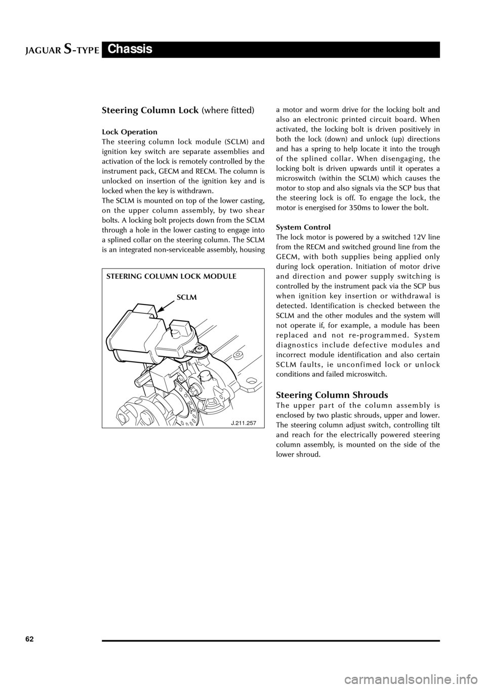
The steering column lock module (SCLM) and
ignition key switch are separate assemblies and
activation of the lock is remotely controlled by the
instrument pack, GECM and RECM. The column is
unlocked on insertion of the ignition key and is
locked when the key is withdrawn.
The SCLM is mounted on top of the lower casting,
on the upper column assembly, by two shear
bolts. A locking bolt projects down from the SCLM
through a hole in the lower casting to engage into
a splined collar on the steering column. The SCLM
is an integrated non-serviceable assembly, housinga motor and worm drive for the locking bolt and
also an electronic printed circuit board. When
activated, the locking bolt is driven positively in
both the lock (down) and unlock (up) directions
and has a spring to help locate it into the trough
of the splined collar. When disengaging, the
locking bolt is driven upwards until it operates a
microswitch (within the SCLM) which causes the
motor to stop and also signals via the SCP bus that
the steering lock is off. To engage the lock, the
motor is energised for 350ms to lower the bolt.
System Control
The lock motor is powered by a switched 12V line
from the RECM and switched ground line from the
GECM, with both supplies being applied only
during lock operation. Initiation of motor drive
and direction and power supply switching is
controlled by the instrument pack via the SCP bus
when ignition key insertion or withdrawal is
detected. Identification is checked between the
SCLM and the other modules and the system will
not operate if, for example, a module has been
replaced and not re-programmed. System
diagnostics include defective modules and
incorrect module identification and also certain
SCLM faults, ie unconfimed lock or unlock
conditions and failed microswitch.
Steering Column Shrouds
The upper part of the column assembly is
enclosed by two plastic shrouds, upper and lower.
The steering column adjust switch, controlling tilt
and reach for the electrically powered steering
column assembly, is mounted on the side of the
lower shroud.
SCLM
Page 73 of 133

JAGUARS-TYPEClimate Control
68Heated wiper park or (where optionally fitted)
heated front screen.
With the engine running, due to the high current
draw, press to switch on the heated wiper park to
defrost the wiper park area, or where fitted, press
to switch on the heated front screen for rapid
defrost/demist.
Heated wiper park automatically operates in cold
weather, and may stay on continuously. It is
automatically switched on when ÔDEFROSTÕ is
selected. If manually selected, the heated wiper
park will automatically switch off after 10
minutes.
Heated front screen is automatically switched on
when ÔDEFROSTÕ is selected. It will automatically
switch off after 4 minutes. The heaters will switch
off, or not operate, if low battery voltage is
detected.
Heated Rear Screen
With the engine running due to the high current
draw, press to switch on the heated rear screen
for rapid defrost/demist. The rear screen heater
will be automatically switched off after 10
minutes.
In cold conditions, the heated rear screen
operates automatically. Selecting ÔDEFROSTÕ will
also turn the heated rear screen ON. The heaters
will switch off, or not operate, if low battery
voltage is detected.
Air Distribution
Air distribution is automatically controlled when
ÔAUTOÕ is selected. Manual control can be
achieved using the air distribution buttons.
Heat at Rest Feature (V8 engine vehicles
only)
Interior heating may be continued after the
engine has been switched off by turning the
ignition to position ÔIIÕ. The climate control system
will continue to provide heat to the vehicle
interior until the engine cools down. Excessive use
will cause a low battery voltage, which may
prevent the vehicle from being started.
Voice Activated Control
Some functions of the climate control system can
be operated with the Voice Activation System
(when fitted).
A full operating description is given in the Voice
Activation Handbook included with the vehicle
literature pack.
Page 74 of 133
JAGUARS-TYPEElectrical/Electronic
69
Power Distribution
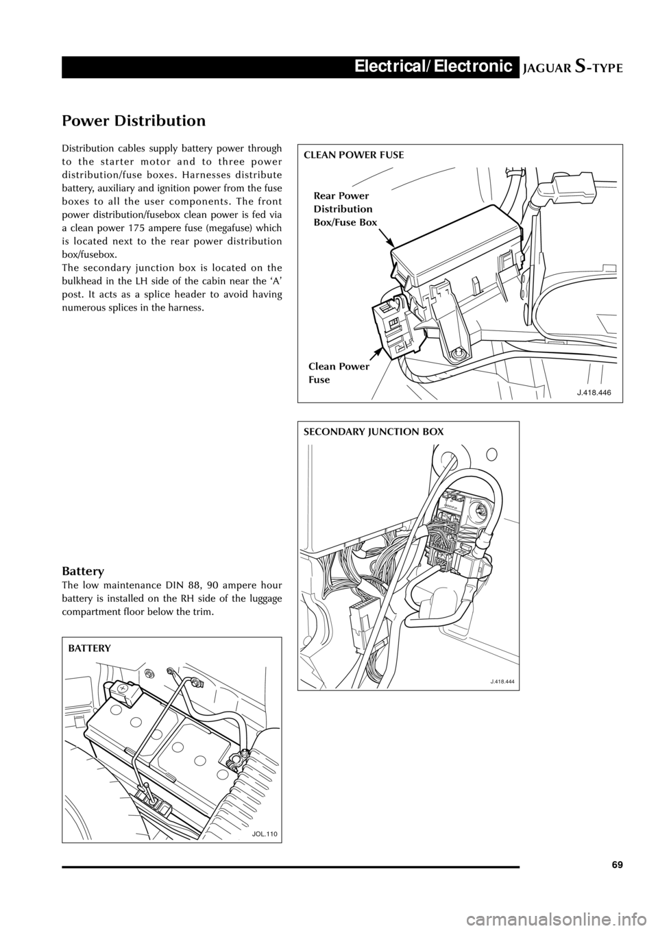
Distribution cables supply battery power through
to the starter motor and to three power
distribution/fuse boxes. Harnesses distribute
battery, auxiliary and ignition power from the fuse
boxes to all the user components. The front
power distribution/fusebox clean power is fed via
a clean power 175 ampere fuse (megafuse) which
is located next to the rear power distribution
box/fusebox.
The secondary junction box is located on the
bulkhead in the LH side of the cabin near the ÔAÕ
post. It acts as a splice header to avoid having
numerous splices in the harness.
J.418.446
CLEAN POWER FUSE
J.418.444
SECONDARY JUNCTION BOX
JOL.110
BATTERY
Rear Power
Distribution
Box/Fuse Box
Clean Power
Fuse
Battery
The low maintenance DIN 88, 90 ampere hour
battery is installed on the RH side of the luggage
compartment floor below the trim.
Page 81 of 133
JAGUARS-TYPEElectrical/Electronic
76Air Conditioning Control Module (A/CCM)
The A/CCM is connected to the SCP
communication network. The A/CCM controls
automatic climate functions that maintain the
vehicle at a constant temperature setting.
Instrument Pack
The instrument pack is connected to the SCP
communication network. The instrument pack
displays information received on the SCP
including speedometer, odometer, fuel, and
message center warnings. The instrument pack
also controls the passive anti-theft system (PATS).
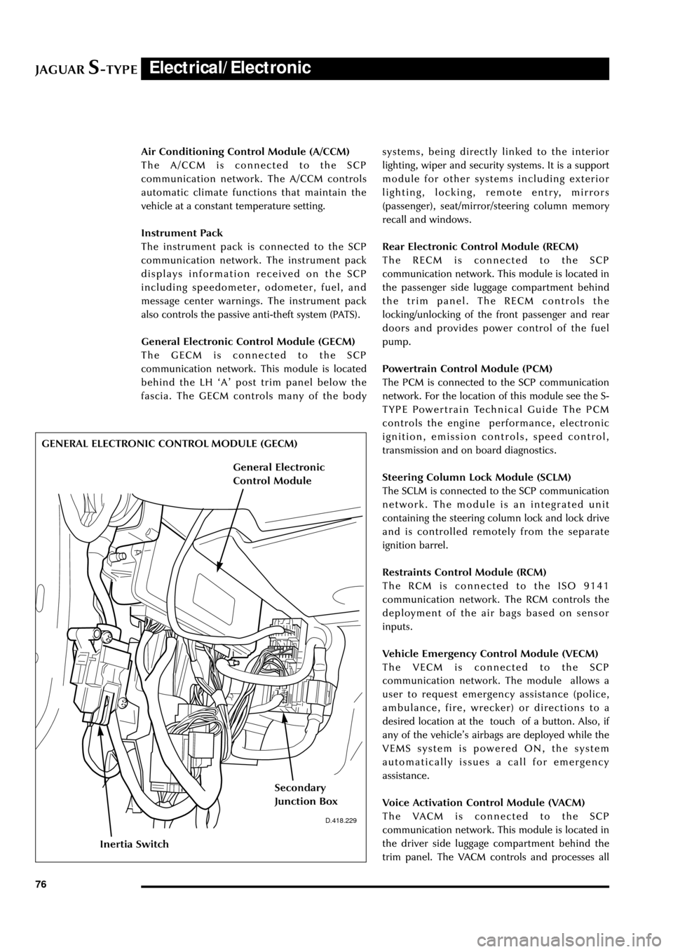
General Electronic Control Module (GECM)
The GECM is connected to the SCP
communication network. This module is located
behind the LH ÔAÕ post trim panel below the
fascia. The GECM controls many of the bodysystems, being directly linked to the interior
lighting, wiper and security systems. It is a support
module for other systems including exterior
lighting, locking, remote entry, mirrors
(passenger), seat/mirror/steering column memory
recall and windows.
Rear Electronic Control Module (RECM)
The RECM is connected to the SCP
communication network. This module is located in
the passenger side luggage compartment behind
the trim panel. The RECM controls the
locking/unlocking of the front passenger and rear
doors and provides power control of the fuel
pump.
Powertrain Control Module (PCM)
The PCM is connected to the SCP communication
network. For the location of this module see the S-
TYPE Powertrain Technical Guide The PCM
controls the engine performance, electronic
ignition, emission controls, speed control,
transmission and on board diagnostics.
Steering Column Lock Module (SCLM)
The SCLM is connected to the SCP communication
network. The module is an integrated unit
containing the steering column lock and lock drive
and is controlled remotely from the separate
ignition barrel.
Restraints Control Module (RCM)
The RCM is connected to the ISO 9141
communication network. The RCM controls the
deployment of the air bags based on sensor
inputs.
Vehicle Emergency Control Module (VECM)
The VECM is connected to the SCP
communication network. The module allows a
user to request emergency assistance (police,
ambulance, fire, wrecker) or directions to a
desired location at the touch of a button. Also, if
any of the vehicleÕs airbags are deployed while the
VEMS system is powered ON, the system
automatically issues a call for emergency
assistance.
Voice Activation Control Module (VACM)
The VACM is connected to the SCP
communication network. This module is located in
the driver side luggage compartment behind the
trim panel. The VACM controls and processes all
D.418.229
GENERAL ELECTRONIC CONTROL MODULE (GECM)
Inertia Switch
Secondary
Junction Box
General Electronic
Control Module