transmission fluid JAGUAR S TYPE 2005 1.G Technical Guide Update
[x] Cancel search | Manufacturer: JAGUAR, Model Year: 2005, Model line: S TYPE, Model: JAGUAR S TYPE 2005 1.GPages: 133, PDF Size: 3.48 MB
Page 58 of 133

JAGUARS-TYPEChassis
53
Driveline
Introduction
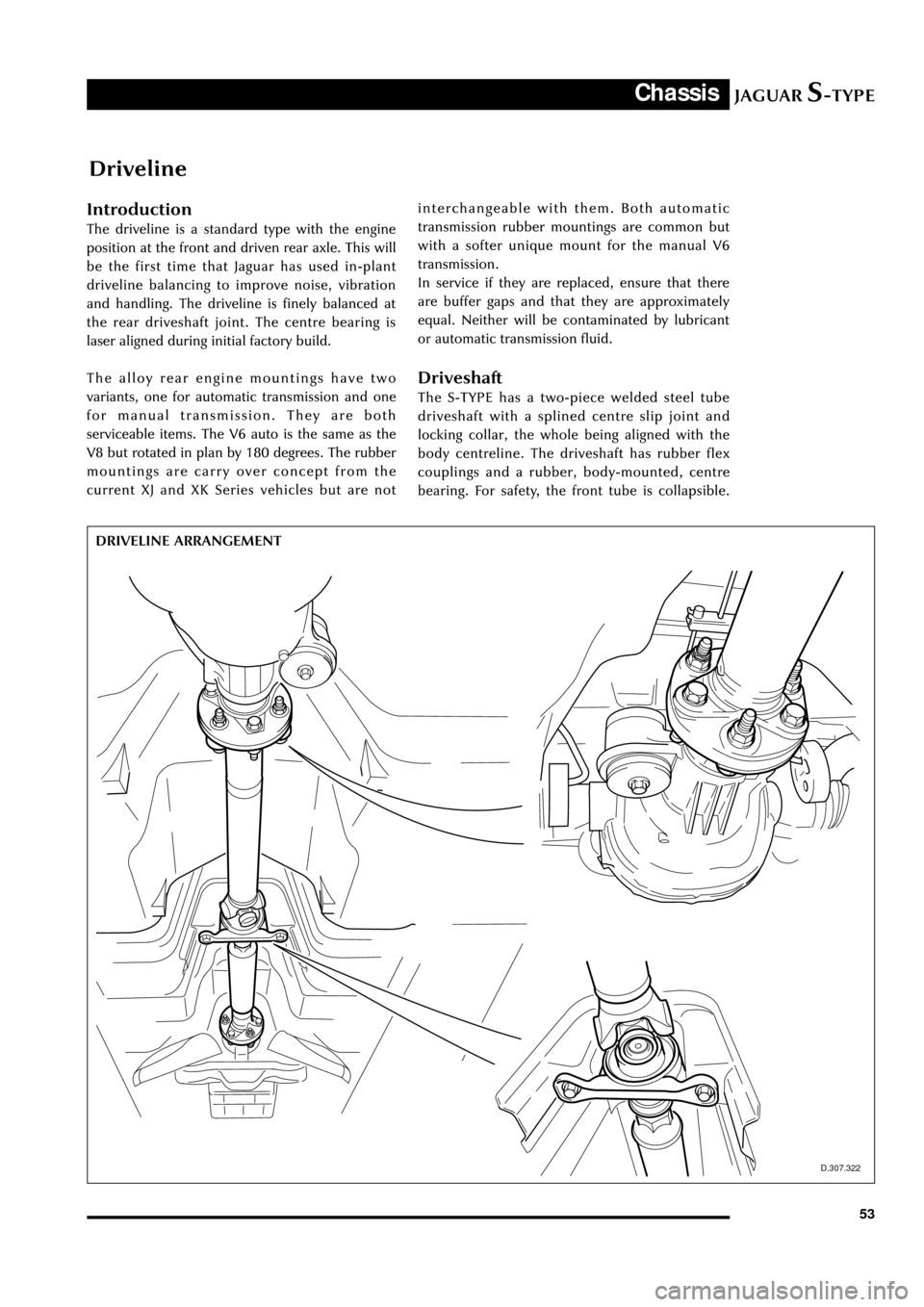
The driveline is a standard type with the engine
position at the front and driven rear axle. This will
be the first time that Jaguar has used in-plant
driveline balancing to improve noise, vibration
and handling. The driveline is finely balanced at
the rear driveshaft joint. The centre bearing is
laser aligned during initial factory build.
The alloy rear engine mountings have two
variants, one for automatic transmission and one
for manual transmission. They are both
serviceable items. The V6 auto is the same as the
V8 but rotated in plan by 180 degrees. The rubber
mountings are carry over concept from the
current XJ and XK Series vehicles but are not
D.307.322
DRIVELINE ARRANGEMENTinterchangeable with them. Both automatic
transmission rubber mountings are common but
with a softer unique mount for the manual V6
transmission.
In service if they are replaced, ensure that there
are buffer gaps and that they are approximately
equal. Neither will be contaminated by lubricant
or automatic transmission fluid.
Driveshaft
The S-TYPE has a two-piece welded steel tube
driveshaft with a splined centre slip joint and
locking collar, the whole being aligned with the
body centreline. The driveshaft has rubber flex
couplings and a rubber, body-mounted, centre
bearing. For safety, the front tube is collapsible.
Page 62 of 133

JAGUARS-TYPEChassis
57
D.206.176
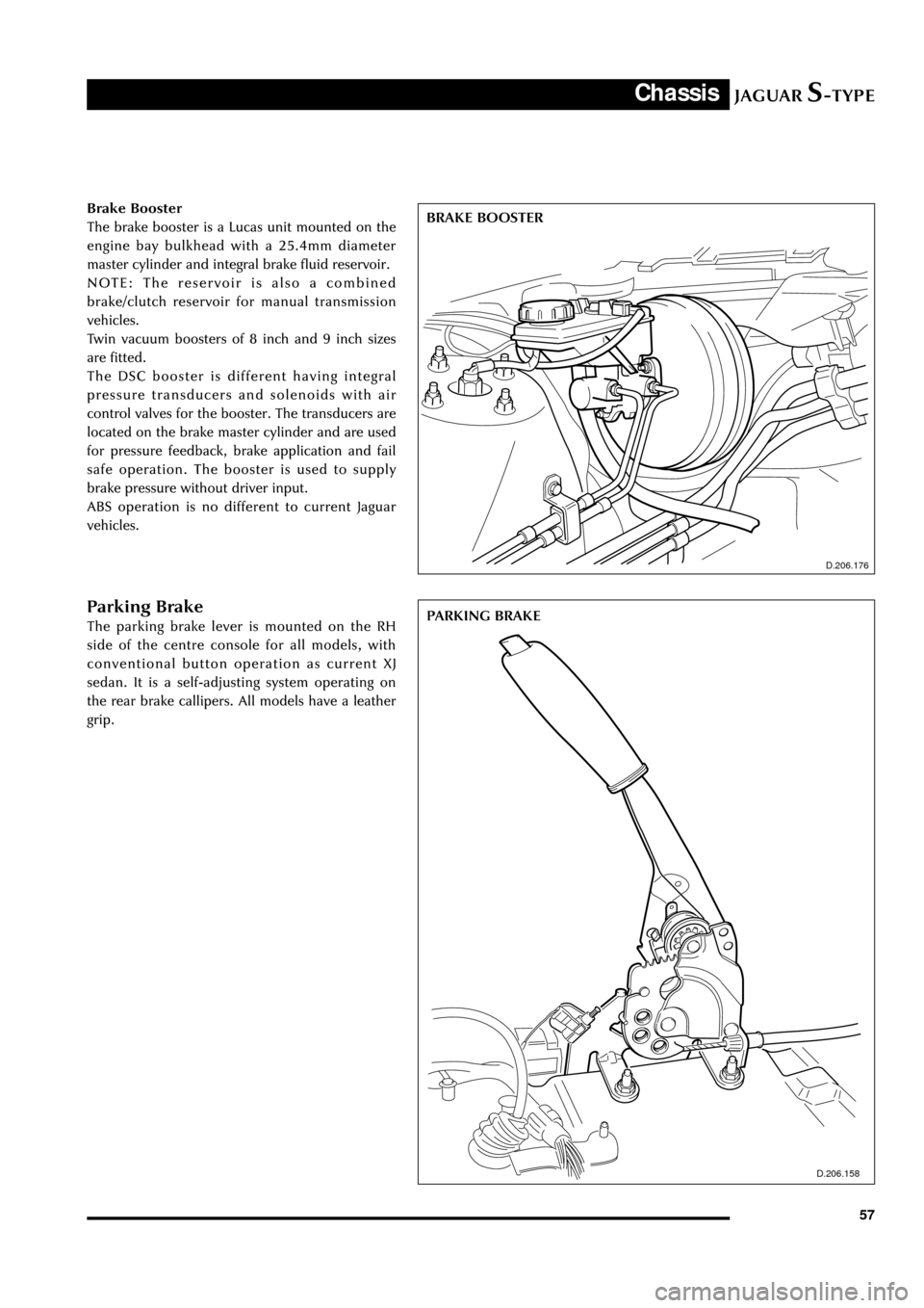
BRAKE BOOSTER Brake Booster
The brake booster is a Lucas unit mounted on the
engine bay bulkhead with a 25.4mm diameter
master cylinder and integral brake fluid reservoir.
NOTE: The reservoir is also a combined
brake/clutch reservoir for manual transmission
vehicles.
Twin vacuum boosters of 8 inch and 9 inch sizes
are fitted.
The DSC booster is different having integral
pressure transducers and solenoids with air
control valves for the booster. The transducers are
located on the brake master cylinder and are used
for pressure feedback, brake application and fail
safe operation. The booster is used to supply
brake pressure without driver input.
ABS operation is no different to current Jaguar
vehicles.
Parking Brake
The parking brake lever is mounted on the RH
side of the centre console for all models, with
conventional button operation as current XJ
sedan. It is a self-adjusting system operating on
the rear brake callipers. All models have a leather
grip.
D.206.158
PARKING BRAKE
Page 64 of 133

JAGUARS-TYPEChassis
59
D.211.248
FRONT STEERING ARM requires a Service tool to assist removal. Low-
pressure hose connections are made using
Constant Tension (CT) clamps. Pinion hydraulic
connections are orientated with the bottom
connector low pressure with the longer nut, as
current vehicles.
The PAS fluid is for PAS only; it is not to be used
for transmissions. After manual filling, the system
must be bled using a vacuum pump to remove all
the air from the system to prevent system noises.
Fluid level is checked through a sight window on
the reservoir.
Components replaceable are complete pump,
steering rack, reservoir or hose assembly.
A non-serviceable 10-micron filter is located
within the reservoir to maintain fluid cleanliness
throughout the life of the vehicle. It is essential as
with all Jaguars that the system does not become
contaminated. Cap all ports on disassembly to
prevent contamination ingress. As with current
vehicles, the fluid and reservoir must be renewed
if any major component is replaced i.e. Rack,
pump or cooler.
The road wheels should be set straight ahead and
the steering wheel locked (using service tool
F7LC-3F732-BF) when removal and assembly of
the steering gear or intermediate shaft is required.
This is necessary to prevent damage to the air bag
clock spring within the steering upper column
assembly. The intermediate shaft can only be
assembled to its mating components in one
location. Steering wheel alignment can only be
achieved by adjustment at the tie-rods. A
dimensional check of the steering rack position
may be necessary to verify rack centre.
Steering Column
The steering column assembly is completely new
and uses no parts from previous Jaguar
assemblies:
¥ Construction of the upper column assembly is
based on the use of aluminium extrusions and
castings.
¥ A two shaft lower column assembly is used.
¥ The electronically controlled steering lock, the
steering column lock module (SCLM), is a
physically separate component from the
ignition switch which is fascia mounted.
¥ The dynamic stability control (DSC) steering
wheel position sensor is fitted to the upper
column assembly.
Steering Wheel
The steering wheel consists of a magnesium
armature with a central steel insert. The steering
column and wheel insert are splined with a flat so
that the wheel can only be fitted in one position.
Any misalignment of the steering wheel is
corrected by adjusting the tie rods. The splined
fitting also has a locking taper which requires the
use of a 2 legged puller to remove the wheel.
The steering wheel incorporates the the airbag
module, horn mechanism and the optional cruise
control and audio/phone switches.