warning light JAGUAR S TYPE 2005 1.G Technical Guide Update
[x] Cancel search | Manufacturer: JAGUAR, Model Year: 2005, Model line: S TYPE, Model: JAGUAR S TYPE 2005 1.GPages: 133, PDF Size: 3.48 MB
Page 81 of 133
JAGUARS-TYPEElectrical/Electronic
76Air Conditioning Control Module (A/CCM)
The A/CCM is connected to the SCP
communication network. The A/CCM controls
automatic climate functions that maintain the
vehicle at a constant temperature setting.
Instrument Pack
The instrument pack is connected to the SCP
communication network. The instrument pack
displays information received on the SCP
including speedometer, odometer, fuel, and
message center warnings. The instrument pack
also controls the passive anti-theft system (PATS).
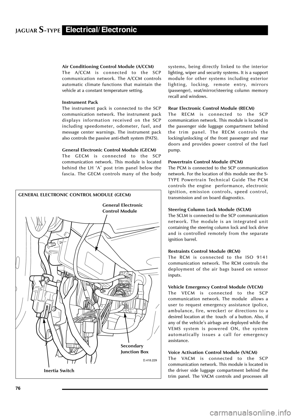
General Electronic Control Module (GECM)
The GECM is connected to the SCP
communication network. This module is located
behind the LH ÔAÕ post trim panel below the
fascia. The GECM controls many of the bodysystems, being directly linked to the interior
lighting, wiper and security systems. It is a support
module for other systems including exterior
lighting, locking, remote entry, mirrors
(passenger), seat/mirror/steering column memory
recall and windows.
Rear Electronic Control Module (RECM)
The RECM is connected to the SCP
communication network. This module is located in
the passenger side luggage compartment behind
the trim panel. The RECM controls the
locking/unlocking of the front passenger and rear
doors and provides power control of the fuel
pump.
Powertrain Control Module (PCM)
The PCM is connected to the SCP communication
network. For the location of this module see the S-
TYPE Powertrain Technical Guide The PCM
controls the engine performance, electronic
ignition, emission controls, speed control,
transmission and on board diagnostics.
Steering Column Lock Module (SCLM)
The SCLM is connected to the SCP communication
network. The module is an integrated unit
containing the steering column lock and lock drive
and is controlled remotely from the separate
ignition barrel.
Restraints Control Module (RCM)
The RCM is connected to the ISO 9141
communication network. The RCM controls the
deployment of the air bags based on sensor
inputs.
Vehicle Emergency Control Module (VECM)
The VECM is connected to the SCP
communication network. The module allows a
user to request emergency assistance (police,
ambulance, fire, wrecker) or directions to a
desired location at the touch of a button. Also, if
any of the vehicleÕs airbags are deployed while the
VEMS system is powered ON, the system
automatically issues a call for emergency
assistance.
Voice Activation Control Module (VACM)
The VACM is connected to the SCP
communication network. This module is located in
the driver side luggage compartment behind the
trim panel. The VACM controls and processes all
D.418.229
GENERAL ELECTRONIC CONTROL MODULE (GECM)
Inertia Switch
Secondary
Junction Box
General Electronic
Control Module
Page 87 of 133

JAGUARS-TYPEElectrical/Electronic
82No Type Rating (amps) Colour Circuit
15 mini 5 Brown Adaptive damping module (ADRC)
16 mini 5 Brown Heated seat switch module,
electrochromic mirror, rain sensor
17 mini 5 Brown RCM, Generator warning lamp
18 mini 20 Yellow Radio, cellular phone, navigation unit
19 mini 15 Blue Steering column motors
20 mini 10 Red GECM, DATC, RECM, Instrument Pack,
brake shift interlock
21 mini 10 Red Power folding mirrors, electric sunblind
22 mini 10 Red DriverÕs door mirror, driverÕs door lock
motor
23 mini 10 Red Right-front high beam
24 mini 5 Brown Passive Anti-Theft System (PATS)
25 mini 10 Red Left-front low beam headlamp
26 - - - Not used
27 mini 10 Red Navigation display, radio, phone,
navigation module, Traffic Master
28 mini 5 Brown Battery-backed security sounder
29 mini 5 Brown Voice control, reversing aid, GECM,
Trailer tow ignition sense, VEMS
30 mini 5 Brown GECM
31 - - - Not used
32 mini 20 Yellow Accessory socket, cigar lighter
33 mini 10 Red GECM illumination power
34 - - - Not used
35 mini 5 Brown Stop lamp switch
Trunk Fusebox
No Type Rating (amps) Colour Circuit
1 mini 15 Blue Luggage compartment release solenoid
2 mini 10 Red Right rear direction indicators, back up,
fog lamps, side markers
3 mini 10 Red Left stop lamp
4 mini 10 Red Fuel door release solenoid
5 mini 10 Red Courtesy and map lamps
6 mini 10 Red Left rear direction indicators, back up,
fog lamps, side markers
7 mini 10 Red Right stop lamp
8 mini 10 Red Center high mounted stop lamp
9 mini 5 Brown Heated mirror
10 mini 5 Brown Traffic Master
11 mini 15 Blue Heated seats
Page 99 of 133
JAGUARS-TYPEElectrical/Electronic
94
Interior Lighting
The automatic operation of the interior lamps is
controlled by the general electronics control
module (GECM).
The interior lighting system consists of the
following lamps:
¥ Two front interior lamps.
¥ Front footwell lamps
¥ Two rear interior lamps with integral reading
lamps.
¥ Front door/puddle lamps
¥ Glove compartment lamp.
¥ Vanity mirror lamps.
¥ Two luggage compartment lamp.
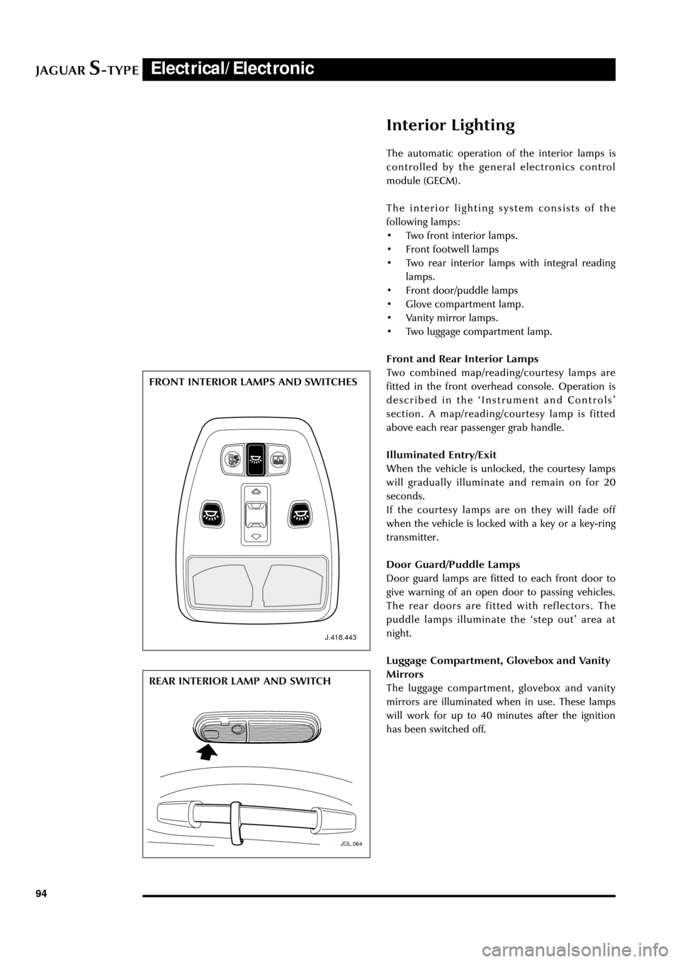
Front and Rear Interior Lamps
Two combined map/reading/courtesy lamps are
fitted in the front overhead console. Operation is
described in the ÔInstrument and ControlsÕ
section. A map/reading/courtesy lamp is fitted
above each rear passenger grab handle.
Illuminated Entry/Exit
When the vehicle is unlocked, the courtesy lamps
will gradually illuminate and remain on for 20
seconds.
If the courtesy lamps are on they will fade off
when the vehicle is locked with a key or a key-ring
transmitter.
Door Guard/Puddle Lamps
Door guard lamps are fitted to each front door to
give warning of an open door to passing vehicles.
The rear doors are fitted with reflectors. The
puddle lamps illuminate the Ôstep outÕ area at
night.
Luggage Compartment, Glovebox and Vanity
Mirrors
The luggage compartment, glovebox and vanity
mirrors are illuminated when in use. These lamps
will work for up to 40 minutes after the ignition
has been switched off.
J.418.443
JOL.064
FRONT INTERIOR LAMPS AND SWITCHES
REAR INTERIOR LAMP AND SWITCH
Page 100 of 133
JAGUARS-TYPEElectrical/Electronic
95
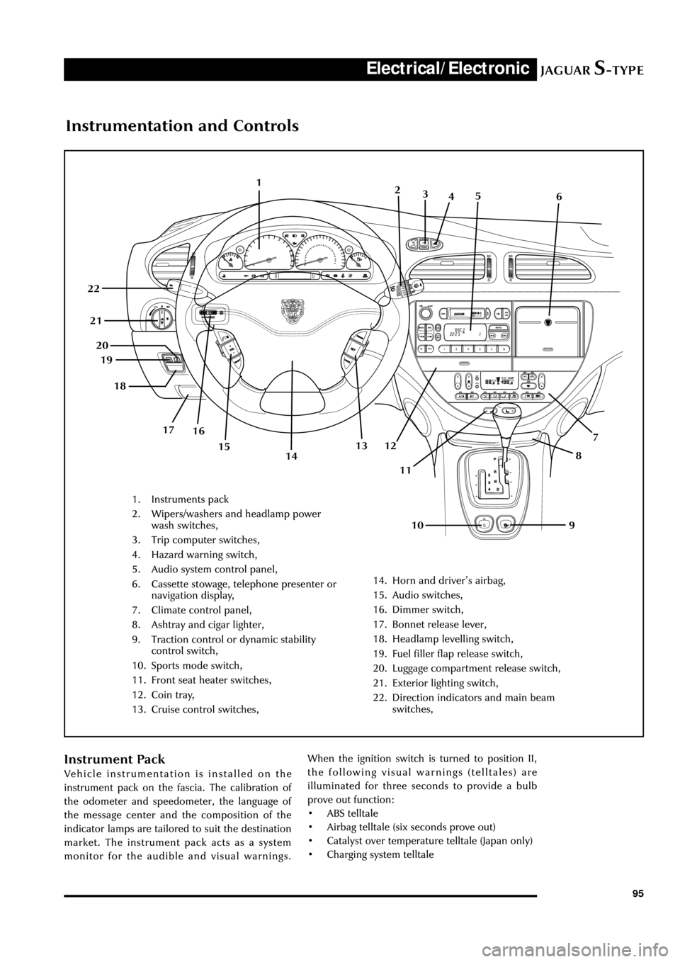
Instrumentation and Controls
1. Instruments pack
2. Wipers/washers and headlamp power
wash switches,
3. Trip computer switches,
4. Hazard warning switch,
5. Audio system control panel,
6. Cassette stowage, telephone presenter or
navigation display,
7. Climate control panel,
8. Ashtray and cigar lighter,
9. Traction control or dynamic stability
control switch,
10. Sports mode switch,
11. Front seat heater switches,
12. Coin tray,
13. Cruise control switches,
14. Horn and driverÕs airbag,
15. Audio switches,
16. Dimmer switch,
17. Bonnet release lever,
18. Headlamp levelling switch,
19. Fuel filler flap release switch,
20. Luggage compartment release switch,
21. Exterior lighting switch,
22. Direction indicators and main beam
switches,
1
7
8
9 10 11 12 13 19
16 17 18 20 21 22
142
3
45
6
15
Instrument Pack
Vehicle instrumentation is installed on the
instrument pack on the fascia. The calibration of
the odometer and speedometer, the language of
the message center and the composition of the
indicator lamps are tailored to suit the destination
market. The instrument pack acts as a system
monitor for the audible and visual warnings.When the ignition switch is turned to position II,
the following visual warnings (telltales) are
illuminated for three seconds to provide a bulb
prove out function:
¥ ABS telltale
¥ Airbag telltale (six seconds prove out)
¥ Catalyst over temperature telltale (Japan only)
¥ Charging system telltale
Page 101 of 133
JAGUARS-TYPEElectrical/Electronic
96
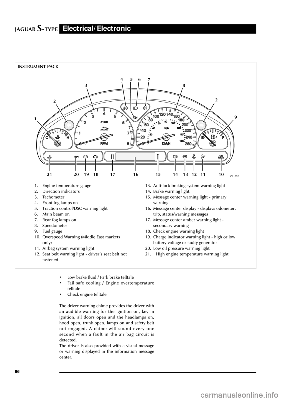
JOL.002
1. Engine temperature gauge
2. Direction indicators
3. Tachometer
4. Front fog lamps on
5. Traction control/DSC warning light
6. Main beam on
7. Rear fog lamps on
8. Speedometer
9. Fuel gauge
10. Overspeed Warning (Middle East markets
only)
11. Airbag system warning light
12. Seat belt warning light - driverÕs seat belt not
fastened13. Anti-lock braking system warning light
14. Brake warning light
15. Message center warning light - primary
warning
16. Message center display - displays odometer,
trip, status/warning messages
17. Message center amber warning light -
secondary warning
18. Check engine warning light
19. Charge indicator warning light - high or low
battery voltage or faulty generator
20. Low oil pressure warning light
21. High engine temperature warning light INSTRUMENT PACK
126 5 4
3
109 8 7
112
13 12 18 20 19 1416 15 17 21
¥ Low brake fluid / Park brake telltale
¥ Fail safe cooling / Engine overtemperature
telltale
¥ Check engine telltale
The driver warning chime provides the driver with
an audible warning for the ignition on, key in
ignition, all doors open and the headlamps on,
hood open, trunk open, lamps on and safety belt
not engaged. A chime will sound every one
second when a fault in the air bag circuit is
detected.
The driver is also provided with a visual message
or warning displayed in the information message
center.
Page 102 of 133
JAGUARS-TYPEElectrical/Electronic
97
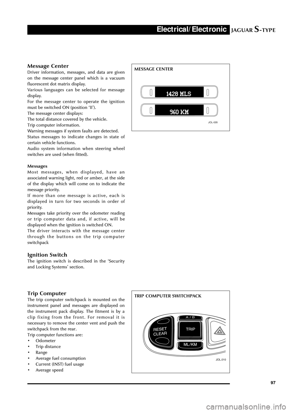
Trip Computer
The trip computer switchpack is mounted on the
instrument panel and messages are displayed on
the instrument pack display. The fitment is by a
clip fixing from the front. For removal it is
necessary to remove the center vent and push the
switchpack from the rear.
Trip computer functions are:
¥ Odometer
¥ Trip distance
¥ Range
¥ Average fuel consumption
¥ Current (INST) fuel usage
¥ Average speed
JOL.010
TRIP COMPUTER SWITCHPACK
Message Center
Driver information, messages, and data are given
on the message center panel which is a vacuum
fluorescent dot matrix display.
Various languages can be selected for message
display.
For the message center to operate the ignition
must be switched ON (position ÔIIÕ).
The message center displays:
The total distance covered by the vehicle.
Trip computer information.
Warning messages if system faults are detected.
Status messages to indicate changes in state of
certain vehicle functions.
Audio system information when steering wheel
switches are used (when fitted).
Messages
Most messages, when displayed, have an
associated warning light, red or amber, at the side
of the display which will come on to indicate the
message priority.
If more than one message is active, each is
displayed in turn for two seconds in order of
priority.
Messages take priority over the odometer reading
or trip computer data and, if active, will be
displayed when the ignition is switched ON.
The driver interacts with the message center
through the buttons on the trip computer
switchpack
Ignition Switch
The ignition switch is described in the ÔSecurity
and Locking SystemsÕ section.
JOL-035
MESSAGE CENTER
Page 106 of 133
JAGUARS-TYPEElectrical/Electronic
101
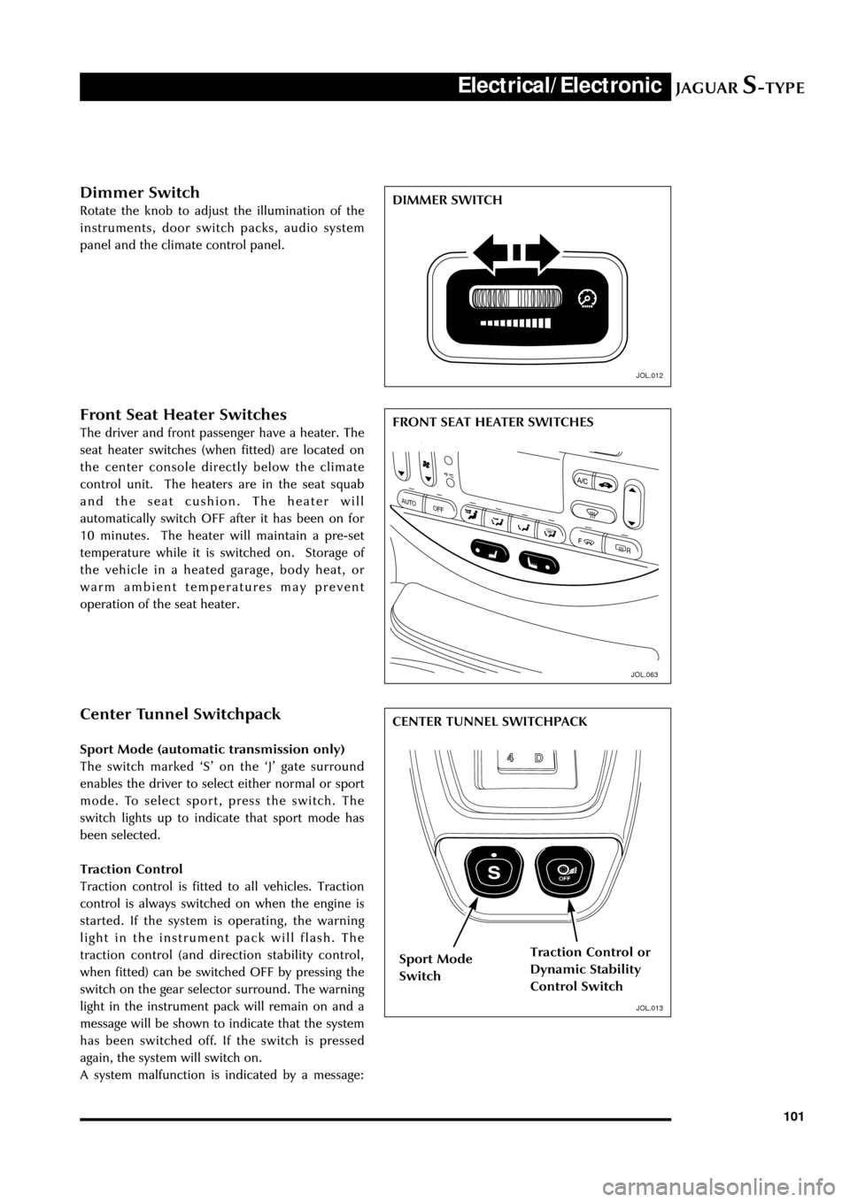
Dimmer Switch
Rotate the knob to adjust the illumination of the
instruments, door switch packs, audio system
panel and the climate control panel.
JOL.063
Front Seat Heater Switches
The driver and front passenger have a heater. The
seat heater switches (when fitted) are located on
the center console directly below the climate
control unit. The heaters are in the seat squab
and the seat cushion. The heater will
automatically switch OFF after it has been on for
10 minutes. The heater will maintain a pre-set
temperature while it is switched on. Storage of
the vehicle in a heated garage, body heat, or
warm ambient temperatures may prevent
operation of the seat heater.
JOL.013
Center Tunnel Switchpack
Sport Mode (automatic transmission only)
The switch marked ÔSÕ on the ÔJÕ gate surround
enables the driver to select either normal or sport
mode. To select sport, press the switch. The
switch lights up to indicate that sport mode has
been selected.
Traction Control
Traction control is fitted to all vehicles. Traction
control is always switched on when the engine is
started. If the system is operating, the warning
light in the instrument pack will flash. The
traction control (and direction stability control,
when fitted) can be switched OFF by pressing the
switch on the gear selector surround. The warning
light in the instrument pack will remain on and a
message will be shown to indicate that the system
has been switched off. If the switch is pressed
again, the system will switch on.
A system malfunction is indicated by a message:DIMMER SWITCH
FRONT SEAT HEATER SWITCHES
CENTER TUNNEL SWITCHPACK
Sport Mode
SwitchTraction Control or
Dynamic Stability
Control Switch
JOL.012
JOL.013
Page 107 of 133
JAGUARS-TYPEElectrical/Electronic
102
Door Switchpacks, Front & Rear
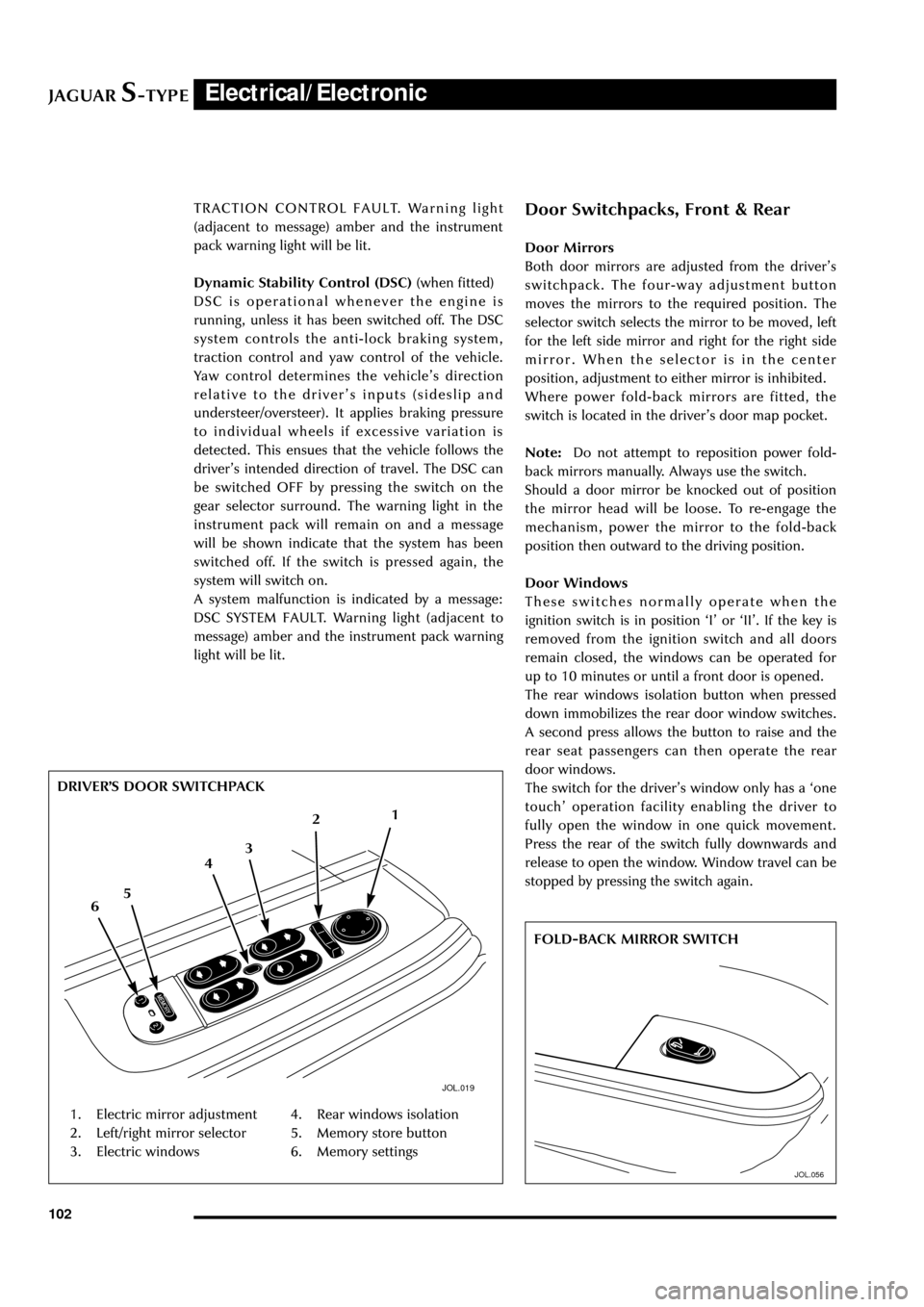
Door Mirrors
Both door mirrors are adjusted from the driverÕs
switchpack. The four-way adjustment button
moves the mirrors to the required position. The
selector switch selects the mirror to be moved, left
for the left side mirror and right for the right side
mirror. When the selector is in the center
position, adjustment to either mirror is inhibited.
Where power fold-back mirrors are fitted, the
switch is located in the driverÕs door map pocket.
Note:Do not attempt to reposition power fold-
back mirrors manually. Always use the switch.
Should a door mirror be knocked out of position
the mirror head will be loose. To re-engage the
mechanism, power the mirror to the fold-back
position then outward to the driving position.
Door Windows
These switches normally operate when the
ignition switch is in position ÔIÕ or ÔIIÕ. If the key is
removed from the ignition switch and all doors
remain closed, the windows can be operated for
up to 10 minutes or until a front door is opened.
The rear windows isolation button when pressed
down immobilizes the rear door window switches.
A second press allows the button to raise and the
rear seat passengers can then operate the rear
door windows.
The switch for the driverÕs window only has a Ôone
touchÕ operation facility enabling the driver to
fully open the window in one quick movement.
Press the rear of the switch fully downwards and
release to open the window. Window travel can be
stopped by pressing the switch again. TRACTION CONTROL FAULT. Warning light
(adjacent to message) amber and the instrument
pack warning light will be lit.
Dynamic Stability Control (DSC) (when fitted)
DSC is operational whenever the engine is
running, unless it has been switched off. The DSC
system controls the anti-lock braking system,
traction control and yaw control of the vehicle.
Yaw control determines the vehicleÕs direction
relative to the driverÕs inputs (sideslip and
understeer/oversteer). It applies braking pressure
to individual wheels if excessive variation is
detected. This ensues that the vehicle follows the
driverÕs intended direction of travel. The DSC can
be switched OFF by pressing the switch on the
gear selector surround. The warning light in the
instrument pack will remain on and a message
will be shown indicate that the system has been
switched off. If the switch is pressed again, the
system will switch on.
A system malfunction is indicated by a message:
DSC SYSTEM FAULT. Warning light (adjacent to
message) amber and the instrument pack warning
light will be lit.
JOL.019
1. Electric mirror adjustment
2. Left/right mirror selector
3. Electric windows4. Rear windows isolation
5. Memory store button
6. Memory settings DRIVERÕS DOOR SWITCHPACK
1
2
6543
JOL.056
FOLD-BACK MIRROR SWITCH
Page 109 of 133
JAGUARS-TYPEElectrical/Electronic
104
Overhead Console
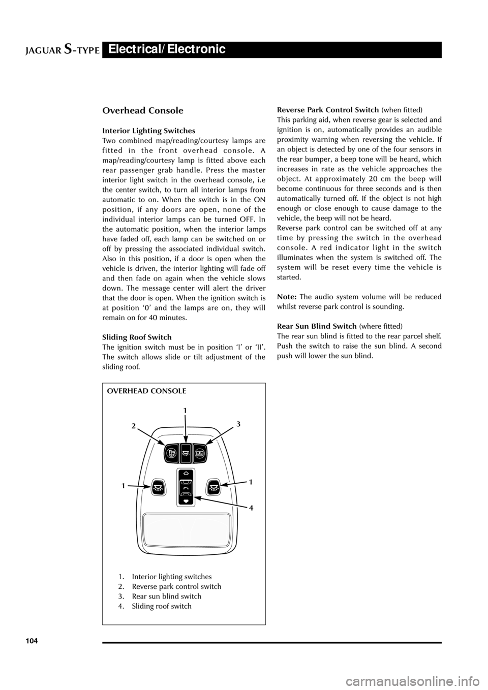
Interior Lighting Switches
Two combined map/reading/courtesy lamps are
fitted in the front overhead console. A
map/reading/courtesy lamp is fitted above each
rear passenger grab handle. Press the master
interior light switch in the overhead console, i.e
the center switch, to turn all interior lamps from
automatic to on. When the switch is in the ON
position, if any doors are open, none of the
individual interior lamps can be turned OFF. In
the automatic position, when the interior lamps
have faded off, each lamp can be switched on or
off by pressing the associated individual switch.
Also in this position, if a door is open when the
vehicle is driven, the interior lighting will fade off
and then fade on again when the vehicle slows
down. The message center will alert the driver
that the door is open. When the ignition switch is
at position Ô0Õ and the lamps are on, they will
remain on for 40 minutes.
Sliding Roof Switch
The ignition switch must be in position ÔIÕ or ÔIIÕ.
The switch allows slide or tilt adjustment of the
sliding roof.
JOL.172
OVERHEAD CONSOLEReverse Park Control Switch (when fitted)
This parking aid, when reverse gear is selected and
ignition is on, automatically provides an audible
proximity warning when reversing the vehicle. If
an object is detected by one of the four sensors in
the rear bumper, a beep tone will be heard, which
increases in rate as the vehicle approaches the
object. At approximately 20 cm the beep will
become continuous for three seconds and is then
automatically turned off. If the object is not high
enough or close enough to cause damage to the
vehicle, the beep will not be heard.
Reverse park control can be switched off at any
time by pressing the switch in the overhead
console. A red indicator light in the switch
illuminates when the system is switched off. The
system will be reset every time the vehicle is
started.
Note:The audio system volume will be reduced
whilst reverse park control is sounding.
Rear Sun Blind Switch (where fitted)
The rear sun blind is fitted to the rear parcel shelf.
Push the switch to raise the sun blind. A second
push will lower the sun blind.
1. Interior lighting switches
2. Reverse park control switch
3. Rear sun blind switch
4. Sliding roof switch
12
1 1
4 3
Page 112 of 133
JAGUARS-TYPEElectrical/Electronic
107
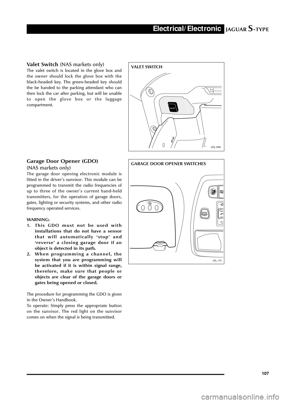
Valet Switch (NAS markets only)
The valet switch is located in the glove box and
the owner should lock the glove box with the
black-headed key. The green-headed key should
the be handed to the parking attendant who can
then lock the car after parking, but will be unable
to open the glove box or the luggage
compartment.
JOL.049
VALET SWITCH
JOL.172
GARAGE DOOR OPENER SWITCHESGarage Door Opener (GDO)
(NAS markets only)
The garage door opening electronic module is
fitted in the driverÕs sunvisor. This module can be
programmed to transmit the radio frequencies of
up to three of the ownerÕs current hand-held
transmitters, for the operation of garage doors,
gates, lighting or security systems, and other radio
frequency operated services.
WARNING:
1. This GDO must not be used with
installations that do not have a sensor
that will automatically ÔstopÕ and
ÔreverseÕ a closing garage door if an
object is detected in its path.
2. When programming a channel, the
system that you are programming will
be activated if it is within signal range,
therefore, make sure that people or
objects are clear of the garage doors or
gates being opened or closed.
The procedure for programming the GDO is given
in the OwnerÕs Handbook.
To operate: Simply press the appropriate button
on the sunvisor. The red light on the sunvisor
comes on when the signal is being transmitted.
JOL.172