Ejb JAGUAR XFR 2010 1.G User Guide
[x] Cancel search | Manufacturer: JAGUAR, Model Year: 2010, Model line: XFR, Model: JAGUAR XFR 2010 1.GPages: 3039, PDF Size: 58.49 MB
Page 1358 of 3039
Published: 11-May-2011
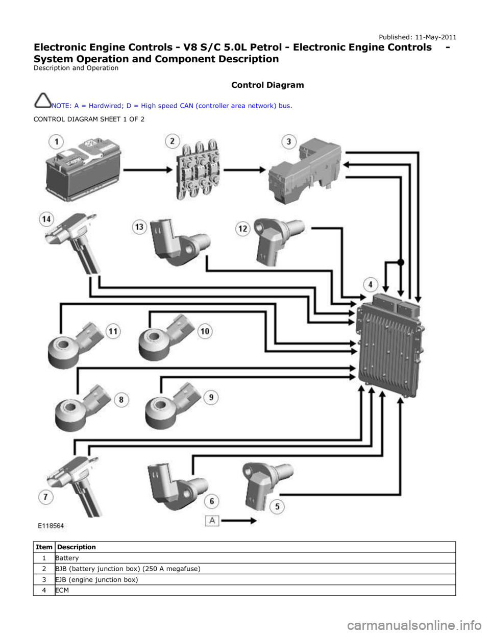
Electronic Engine Controls - V8 S/C 5.0L Petrol - Electronic Engine Controls - System Operation and Component Description
Description and Operation
Control Diagram
NOTE: A = Hardwired; D = High speed CAN (controller area network) bus.
CONTROL DIAGRAM SHEET 1 OF 2
Item Description 1 Battery 2 BJB (battery junction box) (250 A megafuse) 3 EJB (engine junction box) 4 ECM
Page 1411 of 3039

Published: 11-May-2011
Automatic Transmission/Transaxle - TDV6 3.0L Diesel /V8 5.0L Petrol/V8 S/C 5.0L Petrol - Transmission Description - System Operation and Component Description
Description and Operation
Control Diagram
NOTE: A = Hardwired; B = K bus; D = High speed CAN (controller area network) bus; O = LIN (local interconnect
network) bus
Item Description 1 Battery 2 BJB (battery junction box) (250 A megafuse) 3 EJB (engine junction box) 4 CJB (central junction box)
Page 1529 of 3039
Published: 11-May-2011
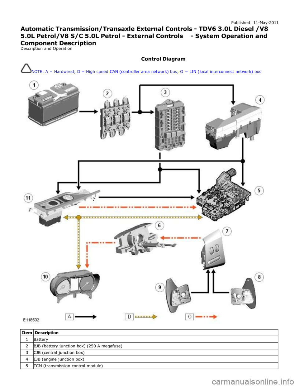
Automatic Transmission/Transaxle External Controls - TDV6 3.0L Diesel /V8 5.0L Petrol/V8 S/C 5.0L Petrol - External Controls - System Operation and
Component Description
Description and Operation
Control Diagram
NOTE: A = Hardwired; D = High speed CAN (controller area network) bus; O = LIN (local interconnect network) bus
Item Description 1 Battery 2 BJB (battery junction box) (250 A megafuse) 3 CJB (central junction box) 4 EJB (engine junction box) 5 TCM (transmission control module)
Page 1711 of 3039
rear window heater switch is pressed or the engine stops.
Automatic operation during a journey is initiated when low ambient air temperatures are experienced and the vehicle has been
travelling for a set period of time above a threshold speed. In this instance, no feedback is given to the driver to inform him
the rear window heater is operational (the switch LED is not illuminated). The duration of heater operation is variable depending on the ambient air temperature, vehicle speed and the amount of time the vehicle has been travelling.
Windshield Heater (Where Fitted)
Windshield heater operation is only enabled when the engine is running. The ATC module controls operation of the windshield heater using two relays in the EJB (engine junction box). When windshield heater operation is required, the ATC module broadcasts a message to the CJB on the medium speed CAN bus. On receipt of the message, the CJB energizes the relays by providing a ground path for both relay coils. This allows a battery feed to flow across the relays to power the windshield left
and right heater elements.
There are two modes of windshield heater operation; manual and automatic.
Manual operation is activated by pressing the windshield heater switch on the integrated control panel. When the switch is
pressed, the status LED in the switch illuminates and the windshield heater elements are energized. Manual operation is discontinued when the windshield heater switch is pressed a second time, 5 minutes have elapsed (the heating phase), or the
engine stops. If manual operation is discontinued by the engine stopping, the previous heating phase is resumed if the engine
is re-started within 30 seconds.
There are two variants of automatic operation; automatic operation at the start of a journey and automatic operation during a
journey.
Automatic operation at the start of a journey is initiated if the ambient air temperature is below 5 °C (41 °F). In this instance,
the switch LED is illuminated and the heater elements are energized for 6.5 minutes. Automatic operation is discontinued if the windshield heater switch is pressed or the engine stops.
Automatic operation during a journey is initiated when low ambient air temperatures are experienced and the vehicle has been
travelling for a set period of time above a threshold speed. In this instance, no feedback is given to the driver to inform him
the windshield heater is operational (the switch LED is not illuminated) and the duration of operation is variable depending upon the ambient air temperature, vehicle speed and the amount of time the vehicle has been travelling.
Exterior Mirror Heaters
Operation of the exterior mirror heaters is fully automatic and not controllable by the driver. Exterior mirror heater operation is
determined by ambient air temperature and windshield wiper status. When ambient air temperature reaches a pre-determined
level, the ATC module broadcasts an exterior mirror heating request to the door modules over the medium speed CAN bus. On receipt of this message, the door modules provide feed and ground connections to both exterior mirror heater elements.
The amount of time the exterior mirror heaters are operational increases if the windshield wipers are switched on. This ensures
the mirrors remain mist free in damp and wet conditions, where there is an increased risk of misting.
Seat Heaters (Where Fitted)
There are four seat heater settings available; off, 1, 2 and 3, which can be selected on the home and climate control screens
of the TSD. The heat setting is relayed to the vehicle occupants through a graduated display on the TSD.
Operation of the heated seats is controlled by the ATC module. When the ATC module receives a heating request from the TSD, it broadcasts a message to the CJB over the medium speed CAN bus. The CJB then provides a hardwired 12 V supply to the three heater elements in the related front seat. The heater elements, two in the seat cushion and one in the seat squab,
are wired in series. The ATC module monitors seat temperature using a temperature sensor located in each seat cushion. The CJB provides the temperature sensors with a 5 V supply. The level of the returned voltage back to the CJB is proportional to the seat temperature. The value of the return signal is broadcast to the ATC module, over the medium speed CAN bus, which allows it to control the seat temperature to the required level. The ATC module will suspend or disable operation of the seat heaters if any of the following occur:
Battery voltage exceeds 16.5 ± 0.3 V for more than 5 seconds. Seat heating is re-enabled when battery voltage
decreases to 16.2 ± 0.3 V.
If a short or open circuit is detected.
If the seat heat temperature rises significantly above the target temperature setting.
The graduated display on the TSD remains illuminated until the seat heaters are turned off or the engine stops. If the engine
is restarted within 30 seconds the seat heater resumes the previous heating level.
Page 1783 of 3039
Published: 11-May-2011
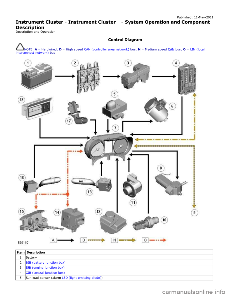
Instrument Cluster - Instrument Cluster - System Operation and Component Description
Description and Operation
Control Diagram
NOTE: A = Hardwired; D = High speed CAN (controller area network) bus; N = Medium speed CAN bus; O = LIN (local interconnect network) bus
Item Description 1 Battery 2 BJB (battery junction box) 3 EJB (engine junction box) 4 CJB (central junction box) 5 Sun load sensor (alarm LED (light emitting diode))
Page 1791 of 3039
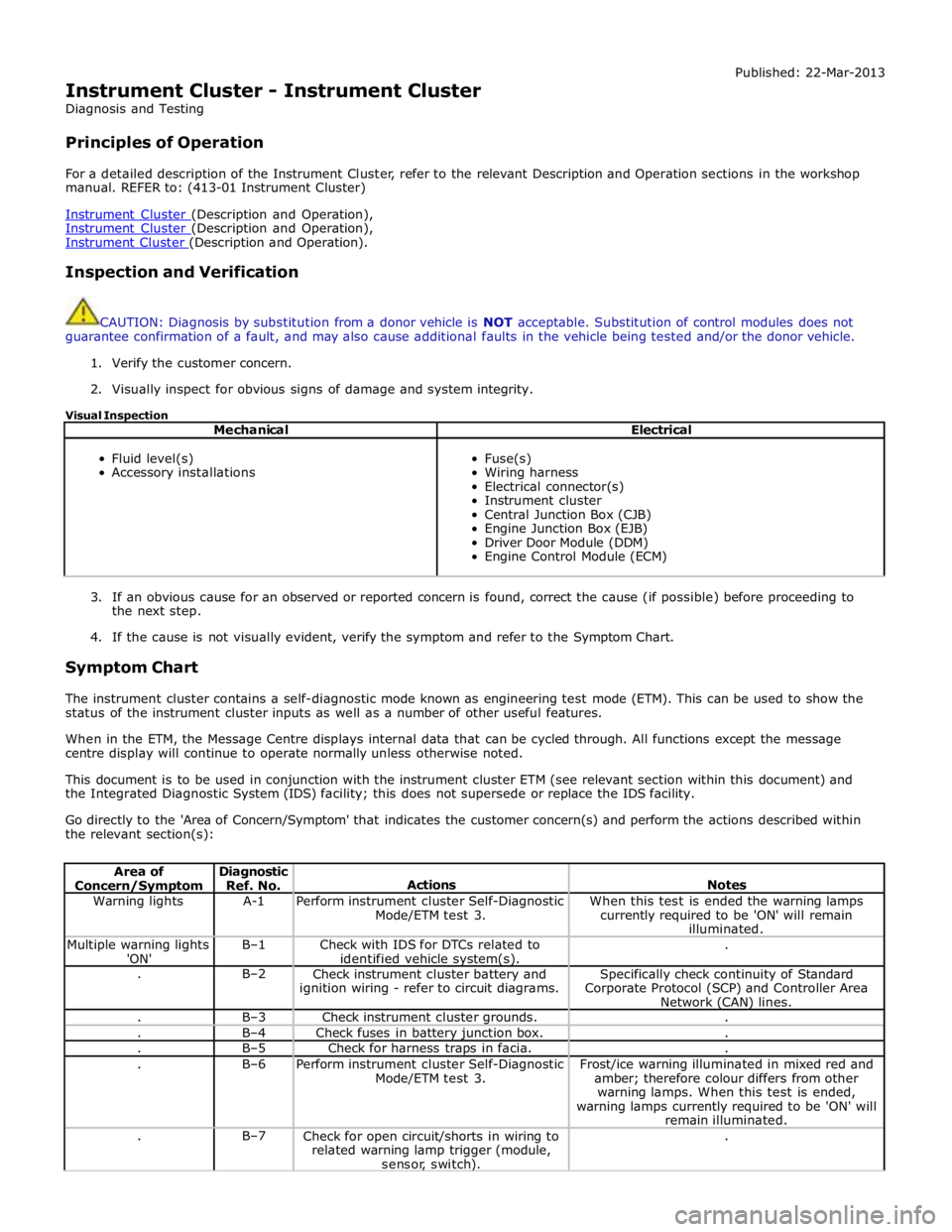
Instrument Cluster - Instrument Cluster
Diagnosis and Testing
Principles of Operation Published: 22-Mar-2013
For a detailed description of the Instrument Cluster, refer to the relevant Description and Operation sections in the workshop
manual. REFER to: (413-01 Instrument Cluster)
Instrument Cluster (Description and Operation), Instrument Cluster (Description and Operation), Instrument Cluster (Description and Operation).
Inspection and Verification
CAUTION: Diagnosis by substitution from a donor vehicle is NOT acceptable. Substitution of control modules does not
guarantee confirmation of a fault, and may also cause additional faults in the vehicle being tested and/or the donor vehicle.
1. Verify the customer concern.
2. Visually inspect for obvious signs of damage and system integrity.
Visual Inspection
Mechanical Electrical
Fluid level(s)
Accessory installations
Fuse(s)
Wiring harness
Electrical connector(s)
Instrument cluster
Central Junction Box (CJB)
Engine Junction Box (EJB)
Driver Door Module (DDM)
Engine Control Module (ECM)
3. If an obvious cause for an observed or reported concern is found, correct the cause (if possible) before proceeding to
the next step.
4. If the cause is not visually evident, verify the symptom and refer to the Symptom Chart.
Symptom Chart
The instrument cluster contains a self-diagnostic mode known as engineering test mode (ETM). This can be used to show the
status of the instrument cluster inputs as well as a number of other useful features.
When in the ETM, the Message Centre displays internal data that can be cycled through. All functions except the message
centre display will continue to operate normally unless otherwise noted.
This document is to be used in conjunction with the instrument cluster ETM (see relevant section within this document) and
the Integrated Diagnostic System (IDS) facility; this does not supersede or replace the IDS facility.
Go directly to the 'Area of Concern/Symptom' that indicates the customer concern(s) and perform the actions described within
the relevant section(s):
Area of Concern/Symptom Diagnostic
Ref. No.
Actions
Notes Warning lights A-1
Perform instrument cluster Self-Diagnostic
Mode/ETM test 3. When this test is ended the warning lamps
currently required to be 'ON' will remain
illuminated. Multiple warning lights
'ON' B–1
Check with IDS for DTCs related to
identified vehicle system(s). . . B–2
Check instrument cluster battery and
ignition wiring - refer to circuit diagrams. Specifically check continuity of Standard
Corporate Protocol (SCP) and Controller Area
Network (CAN) lines. . B–3 Check instrument cluster grounds. . . B–4 Check fuses in battery junction box. . . B–5 Check for harness traps in facia. . . B–6
Perform instrument cluster Self-Diagnostic
Mode/ETM test 3. Frost/ice warning illuminated in mixed red and
amber; therefore colour differs from other
warning lamps. When this test is ended,
warning lamps currently required to be 'ON' will
remain illuminated. . B–7
Check for open circuit/shorts in wiring to
related warning lamp trigger (module,
sensor, switch). .
Page 1876 of 3039

1 EJB (engine junction box) 2 CJB (central junction box) 3 BJB (battery junction box) 4 RJB (rear junction box) 5 BMS (battery monitoring system) 6 Battery 7 ECM (engine control module) 8 Generator
Page 1877 of 3039
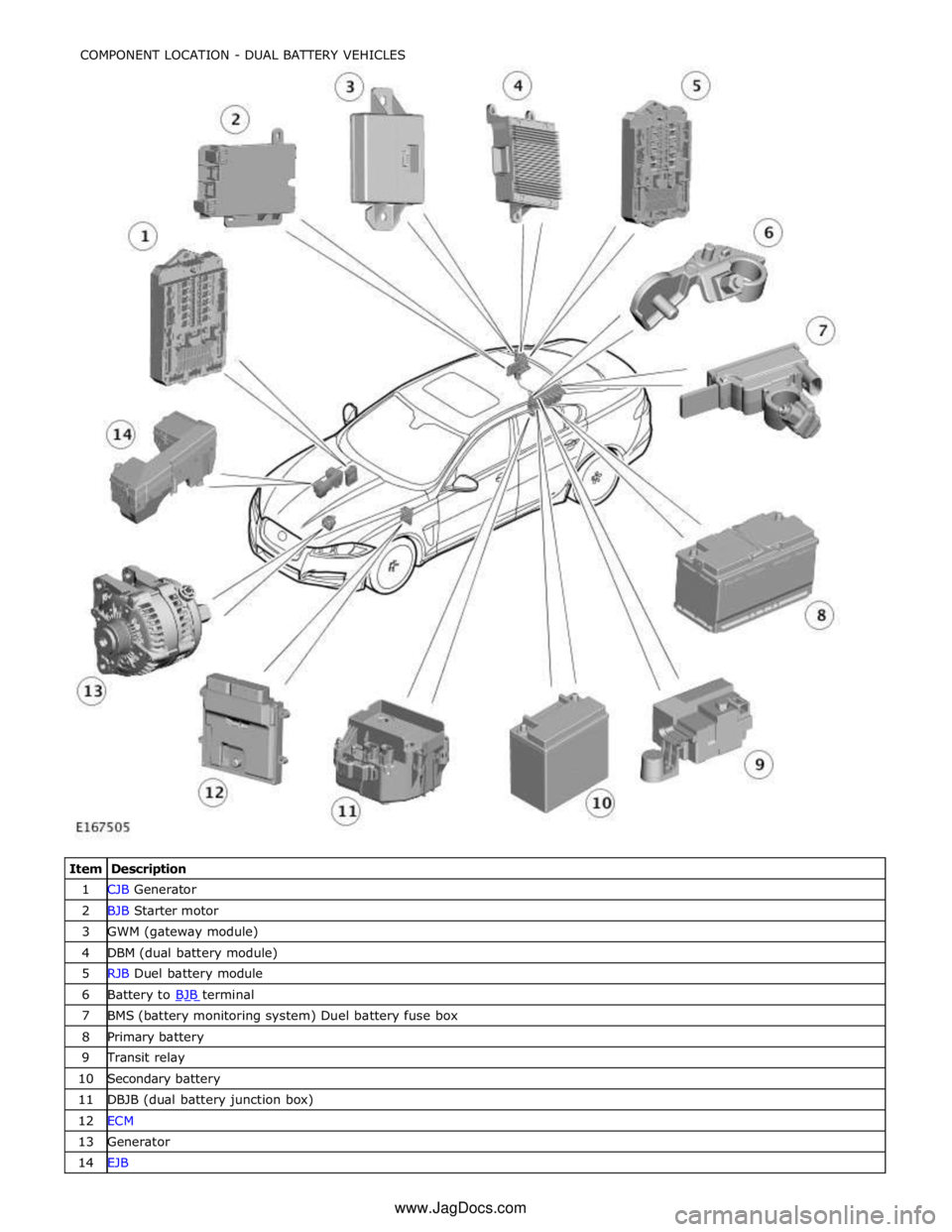
1 CJB Generator 2 BJB Starter motor 3 GWM (gateway module) 4 DBM (dual battery module) 5 RJB Duel battery module 6 Battery to BJB terminal 7 BMS (battery monitoring system) Duel battery fuse box 8 Primary battery 9 Transit relay 10 Secondary battery 11 DBJB (dual battery junction box) 12 ECM 13 Generator 14 EJB COMPONENT LOCATION - DUAL BATTERY VEHICLES
www.JagDocs.com
Page 1878 of 3039
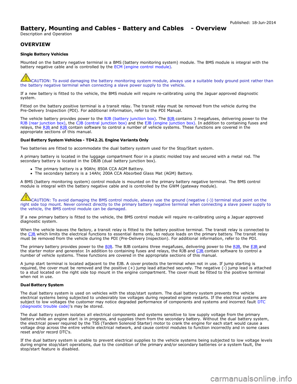
Battery, Mounting and Cables - Battery and Cables - Overview
Description and Operation
OVERVIEW
Single Battery Vehicles Published: 18-Jun-2014
Mounted on the battery negative terminal is a BMS (battery monitoring system) module. The BMS module is integral with the
battery negative cable and is controlled by the ECM (engine control module).
CAUTION: To avoid damaging the battery monitoring system module, always use a suitable body ground point rather than
the battery negative terminal when connecting a slave power supply to the vehicle.
If a new battery is fitted to the vehicle, the BMS module will require re-calibrating using the Jaguar approved diagnostic
system.
Fitted on the battery positive terminal is a transit relay. The transit relay must be removed from the vehicle during the
Pre-Delivery Inspection (PDI). For additional information, refer to the PDI Manual.
The vehicle battery provides power to the BJB (battery junction box). The BJB contains 3 megafuses, delivering power to the RJB (rear junction box), the CJB (central junction box) and the EJB (engine junction box). In addition to containing fuses and
relays, the RJB and RJB contain software to control a number of vehicle systems. These functions are covered in the appropriate sections of this manual.
Dual Battery System Vehicles - TD42.2L Engine Variants Only
Two batteries are fitted to accommodate the dual battery system used for the Stop/Start system.
A primary battery is located in the luggage compartment floor in a plastic molded tray and secured with a metal rod. The
secondary battery is located in the DBJB (dual battery junction box).
The primary battery is a 90Ahr, 850A CCA AGM Battery.
The secondary battery is a 14Ahr, 200A CCA Absorbed Glass Mat (AGM) Battery.
A BMS (battery monitoring system) control module is mounted on the primary battery negative terminal. The BMS control
module is integral with the battery negative cable and is controlled by the GWM (gateway module).
CAUTION: To avoid damaging the BMS control module, always use the ground (negative (-)) terminal stud point on the
right side top mount. Never connect directly to the primary battery negative terminal when connecting a slave power supply to
the vehicle, the BMS control module can be damaged.
If a new primary battery is fitted to the vehicle, the BMS control module will require re-calibrating using a Jaguar approved
diagnostic system.
When the vehicle leaves the factory, a transit relay is fitted to the battery positive terminal. The transit relay is connected to
the CJB which limits the electrical functions to essential items only, to reduce loads on the primary battery. The transit relay must be removed from the vehicle during the PDI (Pre-Delivery Inspection). For additional information, refer to the PDI.
The primary battery provides power to the BJB. The BJB contains three megafuses, delivering power to the RJB, the EJB and the starter motor and generator. In addition to containing fuses and relays, the RJB and CJB contain software to control a number of vehicle systems. These functions are covered in the appropriate sections of this manual.
A jump start terminal is located adjacent to the EJB. A cover protects the terminal when not in use. If jump starting is
required, the cover must be removed and the positive (+) jump lead attached securely. The negative (-) jump lead is attached
to a stud located on the right side top mount in the engine compartment. The cover must be fitted to the positive terminal
when not in use.
Dual Battery System
The dual battery system is used on vehicles with the stop/start system. The dual battery system prevents the vehicle
electrical systems being subjected to undesirably low voltages during repeated engine restarts. If the electrical systems are
subject to low voltages the customer may notice degraded performance of components and systems and incorrect fault DTC
(diagnostic trouble code)'s may be stored.
The dual battery system isolates all electrical components and systems sensitive to low supply voltage from the primary
battery while an engine start is in progress, and supplies them from the secondary battery. Without the dual battery system,
the electrical power required by the TSS (Tandem Solenoid Starter) motor to crank the engine for each start would cause a
voltage drop across the entire vehicle electrical network, and cause control modules to function incorrectly and in some cases
reset and/or record DTC's.
If the dual battery system is unable to prevent electrical supplies to the vehicle systems being subjected to low voltage levels
during engine stop/start operations, due to the condition of the primary and/or secondary batteries or a system fault, the
stop/start feature is disabled.
Page 1881 of 3039
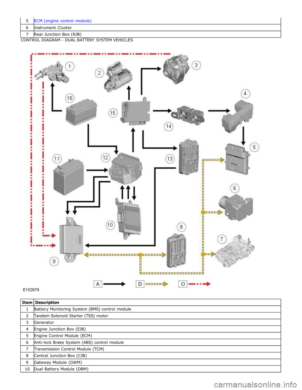
6 Instrument Cluster 7 Rear Junction Box (RJB) CONTROL DIAGRAM - DUAL BATTERY SYSTEM VEHICLES
Item Description 1 Battery Monitoring System (BMS) control module 2 Tandem Solenoid Starter (TSS) motor 3 Generator 4 Engine Junction Box (EJB) 5 Engine Control Module (ECM) 6 Anti-lock Brake System (ABS) control module 7 Transmission Control Module (TCM) 8 Central Junction Box (CJB) 9 Gateway Module (GWM) 10 Dual Battery Module (DBM)