sat nav JAGUAR XFR 2010 1.G User Guide
[x] Cancel search | Manufacturer: JAGUAR, Model Year: 2010, Model line: XFR, Model: JAGUAR XFR 2010 1.GPages: 3039, PDF Size: 58.49 MB
Page 1973 of 3039

Published: 11-May-2011
Information and Entertainment System - Navigation System - Overview
Description and Operation
OVERVIEW
The navigation system provides audible and visual route guidance information to enable the driver to reach a desired
destination. The system allows the driver to choose the desired route using minor or major roads and will present 3 routes to
the driver based on user preferences. Directions to hospitals, museums, monuments and hotels are also available. The
navigation computer uses map information stored on a DVD (digital versatile disc) to determine the best route for the journey
and provide the driver with details of directions and approaching junctions.
The navigation system has various levels of user control through the Touch-screen and JaguarVoice system. System volume
adjustment can be made using the ICP (integrated control panel), Touch-screen and steering wheel controls.
There are 3 navigation system variants specific to various markets. On all systems the GPS (global positioning system) signal
is received by the GPS (global positioning system) antenna located in the roof pod antenna module.
The European navigation system includes the TMC (traffic messaging channel) function, which receives traffic information from
an FM antenna integrated into the heated rear window. On a pre-selected route the system will offer re-routing options
depending on traffic conditions.
The Japanese navigation system includes the VICS (vehicle information and communication systems) function. The VICS
(vehicle information and communication systems) supplies information to enable the navigation computer to re-route the
navigation guidance or to inform the vehicle driver of traffic conditions in the vehicles vicinity. Information is provided to the
system through an FM antenna integrated into the heated rear window and a VICS beacon located in the LH upper side of the
instrument panel.
The NAS (North American specification) variant does not include any additional traffic information systems.
The navigation system is primarily controlled from the Touch-screen which is located in the center of the instrument panel.
Control signals from the Touch-screen are sent on the MOST (media oriented systems transport) ring to the navigation
computer. The navigation computer uses a dedicated GVIF (gigabit video interface) bus to transmit video signals to the Touch-
screen.
Depending upon the audio system version fitted the navigation audio output signals are sent on the MOST (media oriented
systems transport) ring to the IAM (integrated audio module) or the power amplifier for speaker output.
Page 1975 of 3039

7 Microphone 8 Navigation computer 9 VICS (vehicle information and communication system) beacon antenna - Japan only 10 Roof pod antenna module (GPS (global positioning system) antenna) 11 Diversity antenna module (VICS/TMC antenna) 12 ICP (integrated control panel) 13 ICM (information control module) 14 Clock spring 15 Instrument cluster
Authoring Template System Operation
INTRODUCTION TO THE GLOBAL POSITIONING SYSTEM
The system used to calculate the current position of the vehicle is called the GPS. The system utilizes satellites which are owned by the United States Department of Defense. A total of 24 satellites circular orbit the earth every 12 hours at a height
of 20,000 km (12500 miles), and between 5 and 11 of these satellites can be seen from a single point at any given time. The
orbits are tilted to the earth's equator by 55 degrees to ensure coverage of polar regions. Each satellite transmits radio signals
to provide information about the satellite position i.e. latitude, longitude, altitude, almanac data and an accurate time signal
generated by an on-board atomic clock. Each satellite contains four atomic clocks.
The vehicle needs to receive data from at least four different satellites to give a three dimensional fix on its current position.
As the vehicle moves, this information is continually being updated. The computer determines which satellites are 'visible' to
the system and their current position and relationship to each other. Using this information the computer can account for
positional deviations of the satellites and compensate to enhance the accuracy of the navigation system.
www.JagDocs.com
Page 1979 of 3039

VICS (vehicle information and communication system) receiver (Japan only)
TMC (traffic message channel) receiver (Europe only)
JaguarVoice control module
The navigation computer contains a solid state piezo gyro which measures the motion of the vehicle around its vertical axis.
The gyro operates on the principle known as the coriolis force. The coriolis force is the force that appears to accelerate a body
moving away from its rotational axis against the direction of rotation of the axis.
Using inputs from the ABS module, the GPS antenna and the gyro sensor, the computer calculates the vehicle's current position, direction and speed.
The navigation computer houses the DVD (digital versatile disc) drive. The drive is used to read map data from region specific
DVD's. The number of DVD's issued per region varies depending on the amount of information available. The regions are as follows:
Europe (2 versions, Western Europe and Whole of Europe)
NAS (North American specification)
Japan, Middle East, Australia and South Africa
A button, located adjacent to the DVD slot, is provided to eject the DVD from the unit. Prior to ejecting the disc the slot protection has to be slid to the side. If the ignition is on, or the entertainment system is in 1-hour mode, one press of the
button will eject the DVD.
The navigation computer uses non-volatile memory to store settings and configuration information when it is powered down.
This process takes place just before the computer turns off.
No configuration procedure is required if the navigation computer is replaced. There is no option to calibrate the navigation
computer using the Jaguar approved diagnostic equipment; however in some regions a software download, contained in the
DVD disc, is required before the navigation system becomes operational.
MICROPHONE
A single microphone is used for hands-free operation using the JaguarVoice system. The microphone has an integrated noise
suppression system for hands-free use. The microphone is a standard directional type and is located in the front roof overhead
console. The microphone is hardwired to the IAM (integrated audio module). When replacing the microphone extra care must be
taken to make sure it is fitted into its securing clips for correct positioning and orientation.
GPS Antenna
The GPS antenna passes signals from the GPS satellites to the navigation computer for processing. The antenna is located in
Page 1980 of 3039

the roof pod and is shared with the DAB (digital audio broadcasting) band L antenna or satellite radio antenna where fitted.
The roof pod is located externally in a central position towards the rear of the roof.
The GPS antenna is designed with 50 ohm output impedance. The navigation computer is fitted with 50 ohm fakra II connectors to ensure compatibility with the antenna. For optimum performance 50 ohm low loss coaxial cable is used between
the antenna and navigation computer.
It is possible for the GPS antenna to lose the signal from the GPS satellites; In hilly or tree lined areas
Built up areas with tall buildings
In multi storey car parks
In garages
In tunnels
On bridges
During heavy rain or thunderstorms
When the signal is lost the navigation computer will continue to give guidance using memory mapped data from the DVD map until the signal is restored.
TMC/VICS FM Antenna
Data messages for both TMC (traffic message channel) and VICS (vehicle information and communication system) are received
through the FM antennas and diversity antenna module located in the heated rear window.
VICS Beacon Antenna (Japan Only)
The VICS (vehicle information and communication system) beacon antenna receives infra red and RF (radio frequency) traffic
data signals from road side transmitters. The antenna is connected to the navigation computer which incorporates a VICS
(vehicle information and communication system) receiver.
Touch Screen Display
The Touch-screen is the control interface for the following vehicle systems;
System Functions Audio Radio display AM/FM or DAB (digital audio broadcast), auxiliary and portable audio, digital TV or CD Climate
control Air conditioning, distribution, seats, heated steering wheel, automatic air recirculation Telephone Digit dialer, phone book, last ten calls (made, received, missed) www.JagDocs.com
Page 2149 of 3039

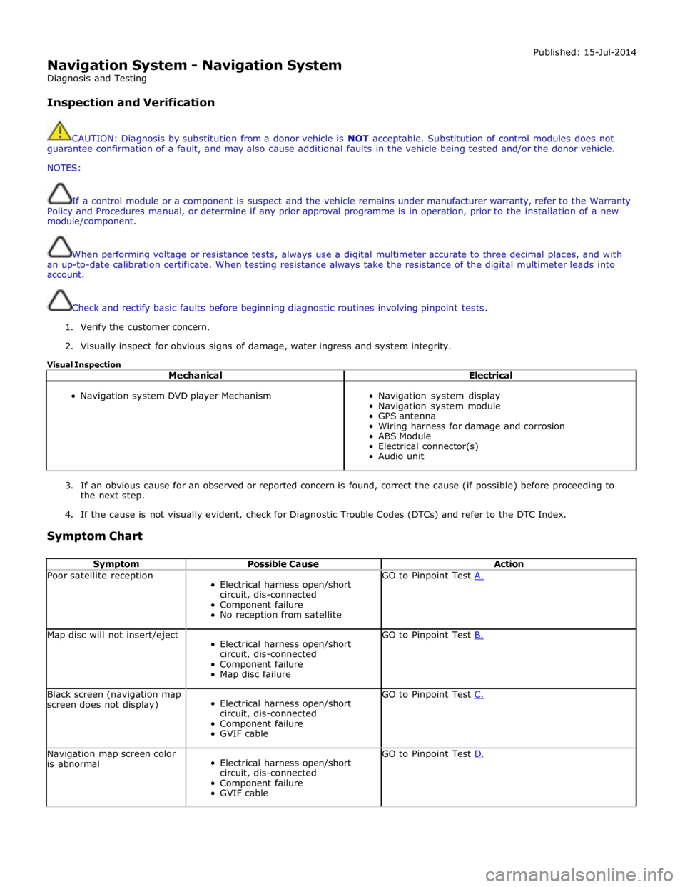
Navigation System - Navigation System
Diagnosis and Testing
Inspection and Verification Published: 15-Jul-2014
CAUTION: Diagnosis by substitution from a donor vehicle is NOT acceptable. Substitution of control modules does not
guarantee confirmation of a fault, and may also cause additional faults in the vehicle being tested and/or the donor vehicle.
NOTES:
If a control module or a component is suspect and the vehicle remains under manufacturer warranty, refer to the Warranty
Policy and Procedures manual, or determine if any prior approval programme is in operation, prior to the installation of a new
module/component.
When performing voltage or resistance tests, always use a digital multimeter accurate to three decimal places, and with
an up-to-date calibration certificate. When testing resistance always take the resistance of the digital multimeter leads into
account.
Check and rectify basic faults before beginning diagnostic routines involving pinpoint tests.
1. Verify the customer concern.
2. Visually inspect for obvious signs of damage, water ingress and system integrity.
Visual Inspection
Mechanical Electrical
Navigation system DVD player Mechanism
Navigation system display
Navigation system module
GPS antenna
Wiring harness for damage and corrosion
ABS Module
Electrical connector(s)
Audio unit
3. If an obvious cause for an observed or reported concern is found, correct the cause (if possible) before proceeding to
the next step.
4. If the cause is not visually evident, check for Diagnostic Trouble Codes (DTCs) and refer to the DTC Index.
Symptom Chart
Symptom Possible Cause Action Poor satellite reception
Electrical harness open/short
circuit, dis-connected
Component failure
No reception from satellite GO to Pinpoint Test A. Map disc will not insert/eject
Electrical harness open/short
circuit, dis-connected
Component failure
Map disc failure GO to Pinpoint Test B. Black screen (navigation map
screen does not display)
Electrical harness open/short
circuit, dis-connected
Component failure
GVIF cable GO to Pinpoint Test C. Navigation map screen color
is abnormal
Electrical harness open/short
circuit, dis-connected
Component failure
GVIF cable GO to Pinpoint Test D.
Page 2150 of 3039

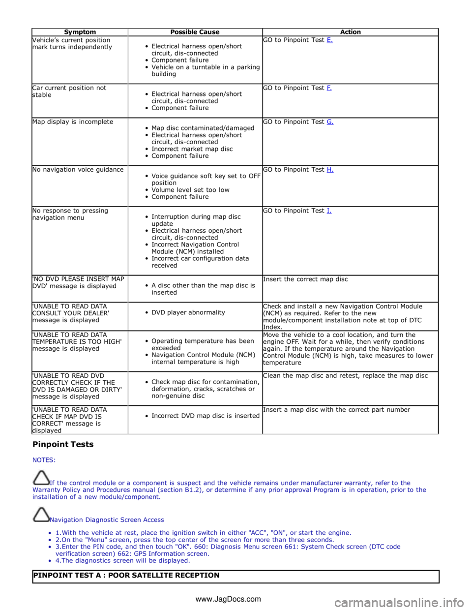
Symptom Possible Cause Action Vehicle’s current position
mark turns independently
Electrical harness open/short
circuit, dis-connected
Component failure
Vehicle on a turntable in a parking
building GO to Pinpoint Test E. Car current position not
stable
Electrical harness open/short
circuit, dis-connected
Component failure GO to Pinpoint Test F. Map display is incomplete
Map disc contaminated/damaged
Electrical harness open/short
circuit, dis-connected
Incorrect market map disc
Component failure GO to Pinpoint Test G. No navigation voice guidance
Voice guidance soft key set to OFF
position
Volume level set too low
Component failure GO to Pinpoint Test H. No response to pressing
navigation menu
Interruption during map disc
update
Electrical harness open/short
circuit, dis-connected
Incorrect Navigation Control
Module (NCM) installed
Incorrect car configuration data
received GO to Pinpoint Test I. 'NO DVD PLEASE INSERT MAP
DVD' message is displayed
A disc other than the map disc is
inserted Insert the correct map disc 'UNABLE TO READ DATA
CONSULT YOUR DEALER'
message is displayed
DVD player abnormality Check and install a new Navigation Control Module
(NCM) as required. Refer to the new
module/component installation note at top of DTC
Index. 'UNABLE TO READ DATA TEMPERATURE IS TOO HIGH'
message is displayed
Operating temperature has been
exceeded
Navigation Control Module (NCM)
internal temperature is high Move the vehicle to a cool location, and turn the
engine OFF. Wait for a while, then verify conditions
again. If the temperature around the Navigation
Control Module (NCM) is high, take measures to lower
temperature 'UNABLE TO READ DVD
CORRECTLY CHECK IF THE
DVD IS DAMAGED OR DIRTY'
message is displayed
Check map disc for contamination,
deformation, cracks, scratches or
non-genuine disc Clean the map disc and retest, replace the map disc 'UNABLE TO READ DATA
CHECK IF MAP DVD IS
CORRECT' message is displayed
Incorrect DVD map disc is inserted Insert a map disc with the correct part number Pinpoint Tests
NOTES:
If the control module or a component is suspect and the vehicle remains under manufacturer warranty, refer to the
Warranty Policy and Procedures manual (section B1.2), or determine if any prior approval Program is in operation, prior to the
installation of a new module/component.
Navigation Diagnostic Screen Access
1. With the vehicle at rest, place the ignition switch in either "ACC", "ON", or start the engine.
2.On the "Menu" screen, press the top center of the screen for more than three seconds.
3. Enter the PIN code, and then touch "OK". 660: Diagnosis Menu screen 661: System Check screen (DTC code
verification screen) 662: GPS Information screen.
4. The diagnostics screen will be displayed.
PINPOINT TEST A : POOR SATELLITE RECEPTION www.JagDocs.com
Page 2152 of 3039

TEST
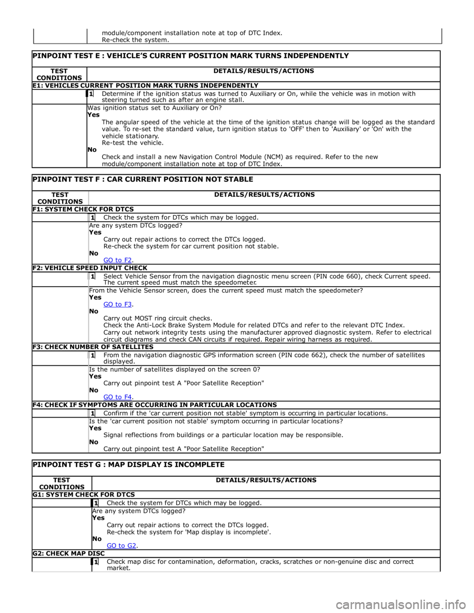
CONDITIONS DETAILS/RESULTS/ACTIONS E1: VEHICLES CURRENT POSITION MARK TURNS INDEPENDENTLY 1 Determine if the ignition status was turned to Auxiliary or On, while the vehicle was in motion with steering turned such as after an engine stall. Was ignition status set to Auxiliary or On?
Yes
The angular speed of the vehicle at the time of the ignition status change will be logged as the standard
value. To re-set the standard value, turn ignition status to 'OFF' then to 'Auxiliary' or 'On' with the
vehicle stationary.
Re-test the vehicle.
No
Check and install a new Navigation Control Module (NCM) as required. Refer to the new module/component installation note at top of DTC Index.
PINPOINT TEST F : CAR CURRENT POSITION NOT STABLE TEST
CONDITIONS DETAILS/RESULTS/ACTIONS F1: SYSTEM CHECK FOR DTCS 1 Check the system for DTCs which may be logged. Are any system DTCs logged? Yes
Carry out repair actions to correct the DTCs logged.
Re-check the system for car current position not stable.
No
GO to F2. F2: VEHICLE SPEED INPUT CHECK 1 Select Vehicle Sensor from the navigation diagnostic menu screen (PIN code 660), check Current speed. The current speed must match the speedometer. From the Vehicle Sensor screen, does the current speed must match the speedometer? Yes
GO to F3. No
Carry out MOST ring circuit checks.
Check the Anti-Lock Brake System Module for related DTCs and refer to the relevant DTC Index.
Carry out network integrity tests using the manufacturer approved diagnostic system. Refer to electrical
circuit diagrams and check CAN circuits if required. Repair wiring harness as required. F3: CHECK NUMBER OF SATELLITES 1 From the navigation diagnostic GPS information screen (PIN code 662), check the number of satellites displayed. Is the number of satellites displayed on the screen 0? Yes
Carry out pinpoint test A "Poor Satellite Reception"
No
GO to F4. F4: CHECK IF SYMPTOMS ARE OCCURRING IN PARTICULAR LOCATIONS 1 Confirm if the 'car current position not stable' symptom is occurring in particular locations. Is the 'car current position not stable' symptom occurring in particular locations? Yes
Signal reflections from buildings or a particular location may be responsible.
No
Carry out pinpoint test A "Poor Satellite Reception"
PINPOINT TEST G : MAP DISPLAY IS INCOMPLETE TEST
CONDITIONS DETAILS/RESULTS/ACTIONS G1: SYSTEM CHECK FOR DTCS 1 Check the system for DTCs which may be logged. Are any system DTCs logged? Yes
Carry out repair actions to correct the DTCs logged.
Re-check the system for 'Map display is incomplete'.
No
GO to G2. G2: CHECK MAP DISC 1 Check map disc for contamination, deformation, cracks, scratches or non-genuine disc and correct market. module/component installation note at top of DTC Index.
Re-check the system.
Page 2172 of 3039

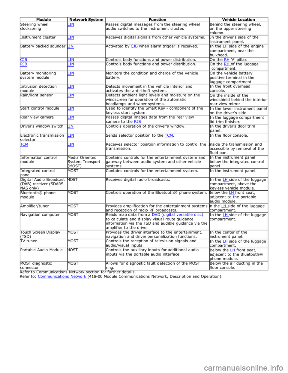
Module Network System Function Vehicle Location
Steering wheel
clockspring LIN Passes digital messages from the steering wheel
audio switches to the instrument cluster. Behind the steering wheel,
on the upper steering
column.
Instrument cluster LIN Receives digital signals from other vehicle systems. On the driver's side of the
instrument panel.
Battery backed sounder LIN Activated by CJB when alarm trigger is received. In the LH side of the engine compartment, near the
bulkhead.
CJB LIN Controls body functions and power distribution. On the RH 'A' pillar.
RJB LIN Controls body functions and power distribution. On the RH of the luggage compartment.
Battery monitoring
system module
Intrusion detection
module LIN Monitors the condition and charge of the vehicle
battery.
LIN Detects movement in the vehicle interior and
activates the anti-theft system. On the vehicle battery
positive terminal in the
luggage compartment.
In the front overhead
console.
Rain/light sensor LIN Detects ambient light levels and moisture on the
windscreen for operation of the automatic
headlamps and wiper systems.
Start control module LIN Used to identify the Smart Key - component of the
keyless start system.
Rear view camera LIN Passes digital images data from the rear view
camera to the RJB On the inside of the
windshield behind the interior
rear view mirror.
In the lower instrument panel
on the driver's side.
In the luggage compartment
lid trim finisher.
Driver's window switch LIN Controls operation of the driver's window. In the driver's door trim
panel.
Electronic transmission
selector LIN Sends selector position to the TCM. In the floor console. TCM LIN Receives selector position information to control the Inside the transmission and
Information control
module
Media Oriented
System Transport
(MOST) transmission.
Contains controls for the entertainment system and
gateway between audio system and other vehicle
systems. accessible by removal of the
fluid pan.
In the instrument panel
below the integrated control
panel.
Integrated control
panel MOST Contains controls for the entertainment system. In the instrument panel.
Digital Audio Broadcast MOST Receives digital radio broadcasts. In the LH side of the luggage (DAB) receiver (SDARS
NAS only)
Bluetooth® phone
module compartment, above the
keyless vehicle module.
MOST Controls operation of the Bluetooth® phone system. Below the LH front seat, adjacent to the portable
audio module.
Amplifier/tuner MOST Provides amplification for the entertainment systems In the LH side of the luggage and reception of radio RF broadcasts.
Navigation computer MOST Reads map data from a DVD (digital versatile disc)
to calculate and display visual route guidance
information via the TSD and audible guidance via the
amplifier to the driver. compartment.
In the LH side of the luggage compartment.
Touch Screen Display
(TSD) MOST Provides the driver interface to the entertainment,
navigation and driver personalization functions. In the center of the
instrument panel.
TV tuner MOST Controls the reception of television signals and
audio/visual inputs.
Portable Audio Module MOST Controls the auxiliary inputs for additional audio
inputs via the portable audio interface. In the LH side of the luggage compartment.
Below the LH front seat, adjacent to the Bluetooth®
phone module.
MOST diagnostic
connector MOST Allows for diagnostic fault detection of the MOST
ring. Below the air ducting in the
floor console.
Refer to Communications Network section for further details.
Refer to: Communications Network (418-00 Module Communications Network, Description and Operation).