Daytime running light JAGUAR XFR 2010 1.G Workshop Manual
[x] Cancel search | Manufacturer: JAGUAR, Model Year: 2010, Model line: XFR, Model: JAGUAR XFR 2010 1.GPages: 3039, PDF Size: 58.49 MB
Page 23 of 3039

Removal and InstallationApproach Lamp
Headlamp Assembly
Headlamp Leveling Front Sensor
Headlamp Leveling Rear Sensor
High Mounted Stoplamp
Rear Fog Lamp
Rear Lamp Assembly
Side Turn Signal Lamp417-02: Interior Lighting
Description and OperationComponent Location
Overview
System Operation and Component DescriptionDiagnosis and TestingInterior Lighting417-04: Daytime Running Lamps (DRL)
Description and OperationOverview
System Operation and Component Description418: Electrical Distribution
418-00: Module Communications Network
Description and OperationOverview
System Operation and Component DescriptionDiagnosis and TestingCommunications NetworkRemoval and InstallationAuxiliary Junction Box (AJB)
Central Junction Box (CJB)418-02: Wiring Harnesses
Description and OperationWiring HarnessGeneral ProceduresWiring Harness RepairRemoval and InstallationLuggage Compartment Lid Wiring Harness419: Electronic Feature Group
419-01A: Anti-Theft - Active
Description and OperationComponent Location
Overview
Page 2028 of 3039

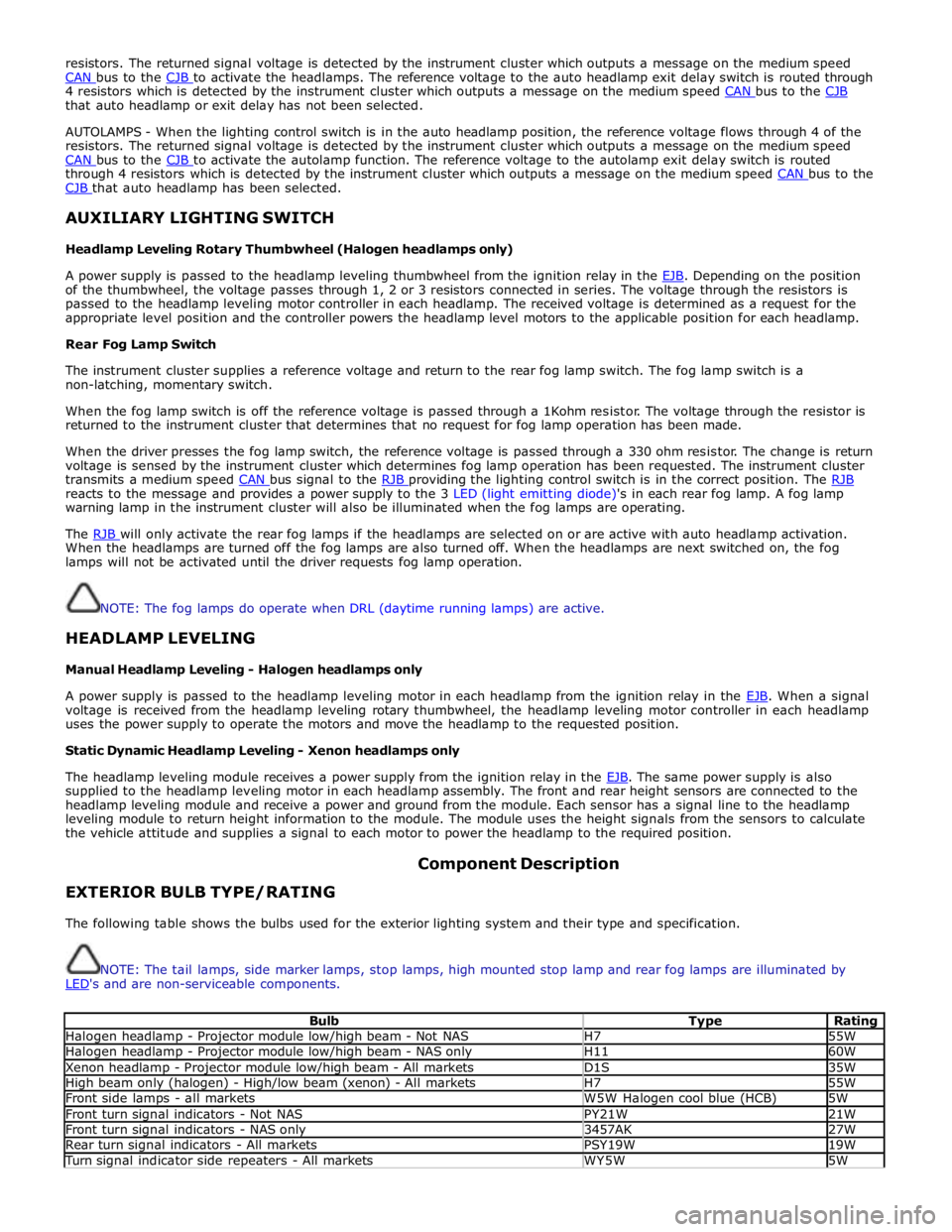
resistors. The returned signal voltage is detected by the instrument cluster which outputs a message on the medium speed
CAN bus to the CJB to activate the headlamps. The reference voltage to the auto headlamp exit delay switch is routed through 4 resistors which is detected by the instrument cluster which outputs a message on the medium speed CAN bus to the CJB that auto headlamp or exit delay has not been selected.
AUTOLAMPS - When the lighting control switch is in the auto headlamp position, the reference voltage flows through 4 of the
resistors. The returned signal voltage is detected by the instrument cluster which outputs a message on the medium speed
CAN bus to the CJB to activate the autolamp function. The reference voltage to the autolamp exit delay switch is routed through 4 resistors which is detected by the instrument cluster which outputs a message on the medium speed CAN bus to the CJB that auto headlamp has been selected.
AUXILIARY LIGHTING SWITCH
Headlamp Leveling Rotary Thumbwheel (Halogen headlamps only)
A power supply is passed to the headlamp leveling thumbwheel from the ignition relay in the EJB. Depending on the position of the thumbwheel, the voltage passes through 1, 2 or 3 resistors connected in series. The voltage through the resistors is
passed to the headlamp leveling motor controller in each headlamp. The received voltage is determined as a request for the
appropriate level position and the controller powers the headlamp level motors to the applicable position for each headlamp.
Rear Fog Lamp Switch
The instrument cluster supplies a reference voltage and return to the rear fog lamp switch. The fog lamp switch is a
non-latching, momentary switch.
When the fog lamp switch is off the reference voltage is passed through a 1Kohm resistor. The voltage through the resistor is
returned to the instrument cluster that determines that no request for fog lamp operation has been made.
When the driver presses the fog lamp switch, the reference voltage is passed through a 330 ohm resistor. The change is return
voltage is sensed by the instrument cluster which determines fog lamp operation has been requested. The instrument cluster
transmits a medium speed CAN bus signal to the RJB providing the lighting control switch is in the correct position. The RJB reacts to the message and provides a power supply to the 3 LED (light emitting diode)'s in each rear fog lamp. A fog lamp
warning lamp in the instrument cluster will also be illuminated when the fog lamps are operating.
The RJB will only activate the rear fog lamps if the headlamps are selected on or are active with auto headlamp activation. When the headlamps are turned off the fog lamps are also turned off. When the headlamps are next switched on, the fog
lamps will not be activated until the driver requests fog lamp operation.
NOTE: The fog lamps do operate when DRL (daytime running lamps) are active.
HEADLAMP LEVELING
Manual Headlamp Leveling - Halogen headlamps only
A power supply is passed to the headlamp leveling motor in each headlamp from the ignition relay in the EJB. When a signal voltage is received from the headlamp leveling rotary thumbwheel, the headlamp leveling motor controller in each headlamp
uses the power supply to operate the motors and move the headlamp to the requested position.
Static Dynamic Headlamp Leveling - Xenon headlamps only
The headlamp leveling module receives a power supply from the ignition relay in the EJB. The same power supply is also supplied to the headlamp leveling motor in each headlamp assembly. The front and rear height sensors are connected to the
headlamp leveling module and receive a power and ground from the module. Each sensor has a signal line to the headlamp
leveling module to return height information to the module. The module uses the height signals from the sensors to calculate
the vehicle attitude and supplies a signal to each motor to power the headlamp to the required position.
EXTERIOR BULB TYPE/RATING Component Description
The following table shows the bulbs used for the exterior lighting system and their type and specification.
NOTE: The tail lamps, side marker lamps, stop lamps, high mounted stop lamp and rear fog lamps are illuminated by
LED's and are non-serviceable components.
Bulb Type Rating Halogen headlamp - Projector module low/high beam - Not NAS H7 55W Halogen headlamp - Projector module low/high beam - NAS only H11 60W Xenon headlamp - Projector module low/high beam - All markets D1S 35W High beam only (halogen) - High/low beam (xenon) - All markets H7 55W Front side lamps - all markets W5W Halogen cool blue (HCB) 5W Front turn signal indicators - Not NAS PY21W 21W Front turn signal indicators - NAS only 3457AK 27W Rear turn signal indicators - All markets PSY19W 19W Turn signal indicator side repeaters - All markets WY5W 5W
Page 2034 of 3039

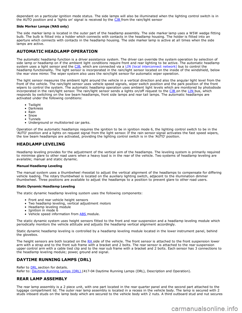
dependant on a particular ignition mode status. The side lamps will also be illuminated when the lighting control switch is in
the AUTO position and a 'lights on' signal is received by the CJB from the rain/light sensor Side Marker Lamps (NAS only)
The side marker lamp is located in the outer part of the headlamp assembly. The side marker lamp uses a W5W wedge fitting
bulb. The bulb is fitted into a holder which connects with contacts in the headlamp housing. The holder is fitted into an
aperture which connects with contacts in the headlamp housing. The side marker lamp is active at all times when the side
lamps are active.
AUTOMATIC HEADLAMP OPERATION
The automatic headlamp function is a driver assistance system. The driver can override the system operation by selection of
side lamp or headlamp on if the ambient light conditions require front and rear lighting to be active. The automatic headlamp
system uses a light sensor and the CJB, which are connected via a LIN (local interconnect network) bus to control the headlamp functionality. The light sensor is incorporated in the rain/light sensor located on the inside of the windshield, below
the rear view mirror. The wiper system also uses the rain/light sensor for automatic wiper operation.
The light sensor measures the ambient light around the vehicle in a vertical direction and also the angular light level from the
front of the vehicle. The rain/light sensor uses vehicle speed signals, wiper switch position and the park position of the front
wipers to control the system. The automatic headlamp operation uses ambient light levels which are monitored by photodiode
incorporated in the rain/light sensor. The rain/light sensor sends a lights on/off request to the CJB on the LIN bus, which responds by switching on the low beam headlamps, front side lamps and rear tail lamps. The automatic headlamps are
activated under the following conditions:
Twilight
Darkness
Rain
Snow
Tunnels
Underground or multistoried car parks.
Operation of the automatic headlamps requires the ignition to be in ignition mode 6, the lighting control switch to be in the
'AUTO' position and a lights on request signal from the light sensor. If the rain sensor signal activates the fast speed wipers,
the low beam headlamps are activated, providing the lighting control switch is in the 'AUTO' position.
HEADLAMP LEVELING
Headlamp leveling provides for the adjustment of the vertical aim of the headlamps. The leveling system is primarily required
to minimise glare to other road users when a heavy load is in the rear of the vehicle. Two systems of headlamp leveling are
available; manual and static dynamic.
Manual Headlamp Leveling
The manual system uses a thumbwheel rheostat to adjust the vertical alignment of the headlamps to compensate for differing
vehicle loading. The rotary thumbwheel is located on the auxiliary lighting switch, adjacent to the illumination dimmer
thumbwheel. Three positions are available to adjust the headlamps to a position to prevent glare to other road users.
Static Dynamic Headlamp Leveling
The static dynamic headlamp leveling system uses the following components:
Front and rear vehicle height sensors
Two headlamp leveling, vertical adjustment motors
Headlamp leveling module
Ignition in mode 6
Vehicle speed information from ABS module.
The static dynamic system uses height sensors fitted to the front and rear suspension and a headlamp leveling module which
periodically monitors the vehicle attitude and adjusts the headlamp vertical alignment accordingly.
Static dynamic headlamp leveling is controlled by a headlamp leveling module located in the lower instrument panel, behind
the glovebox.
The height sensors are both located on the RH side of the vehicle. The front sensor is attached to the front suspension lower arm with a strap and to the front sub frame with a bracket and 2 bolts. The rear sensor is attached to the rear suspension
upper control arm with a cable tied clip and to the rear sub frame with a bracket and 2 bolts. Each sensor has 3 connections to
the headlamp leveling module; power, ground and signal.
DAYTIME RUNNING LAMPS (DRL)
Refer to DRL section for details. Refer to: Daytime Running Lamps (DRL) (417-04 Daytime Running Lamps (DRL), Description and Operation).
REAR LAMP ASSEMBLY
The rear lamp assembly is a 2 piece unit, with one part located in the rear quarter panel and the second part attached to the
luggage compartment lid. The outer rear lamp assembly is located in a recess in the vehicle body. The lamp is secured with 2
studs inboard studs on the lamp body which are secured to the vehicle body with 2 nuts. A third outboard stud and nut secures
Page 2066 of 3039

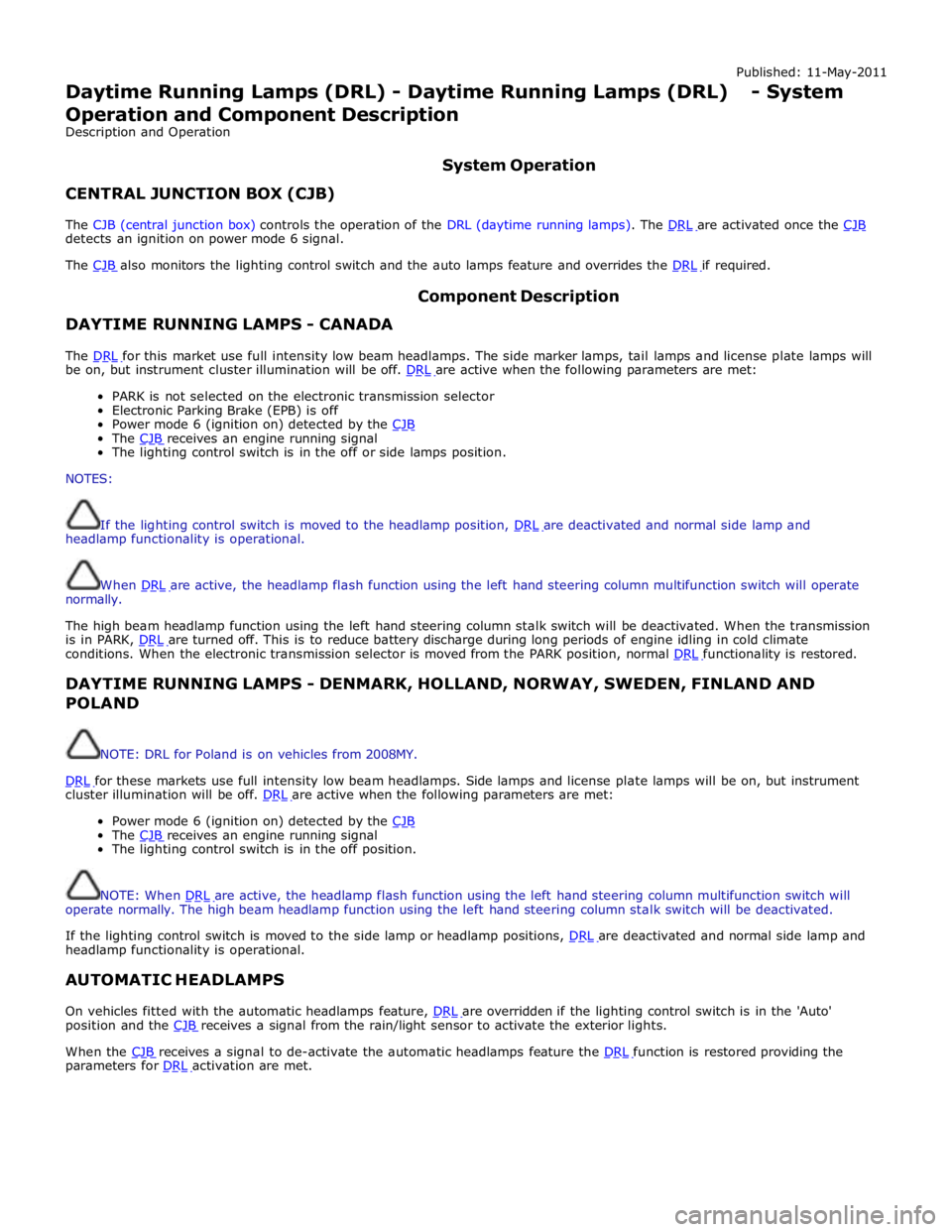
Published: 11-May-2011
Daytime Running Lamps (DRL) - Daytime Running Lamps (DRL) - System
Operation and Component Description
Description and Operation
CENTRAL JUNCTION BOX (CJB) System Operation
The CJB (central junction box) controls the operation of the DRL (daytime running lamps). The DRL are activated once the CJB detects an ignition on power mode 6 signal.
The CJB also monitors the lighting control switch and the auto lamps feature and overrides the DRL if required.
DAYTIME RUNNING LAMPS - CANADA Component Description
The DRL for this market use full intensity low beam headlamps. The side marker lamps, tail lamps and license plate lamps will be on, but instrument cluster illumination will be off. DRL are active when the following parameters are met:
PARK is not selected on the electronic transmission selector
Electronic Parking Brake (EPB) is off
Power mode 6 (ignition on) detected by the CJB The CJB receives an engine running signal The lighting control switch is in the off or side lamps position.
NOTES:
If the lighting control switch is moved to the headlamp position, DRL are deactivated and normal side lamp and headlamp functionality is operational.
When DRL are active, the headlamp flash function using the left hand steering column multifunction switch will operate normally.
The high beam headlamp function using the left hand steering column stalk switch will be deactivated. When the transmission
is in PARK, DRL are turned off. This is to reduce battery discharge during long periods of engine idling in cold climate conditions. When the electronic transmission selector is moved from the PARK position, normal DRL functionality is restored.
DAYTIME RUNNING LAMPS - DENMARK, HOLLAND, NORWAY, SWEDEN, FINLAND AND POLAND
NOTE: DRL for Poland is on vehicles from 2008MY.
DRL for these markets use full intensity low beam headlamps. Side lamps and license plate lamps will be on, but instrument cluster illumination will be off. DRL are active when the following parameters are met:
Power mode 6 (ignition on) detected by the CJB The CJB receives an engine running signal The lighting control switch is in the off position.
NOTE: When DRL are active, the headlamp flash function using the left hand steering column multifunction switch will operate normally. The high beam headlamp function using the left hand steering column stalk switch will be deactivated.
If the lighting control switch is moved to the side lamp or headlamp positions, DRL are deactivated and normal side lamp and headlamp functionality is operational.
AUTOMATIC HEADLAMPS
On vehicles fitted with the automatic headlamps feature, DRL are overridden if the lighting control switch is in the 'Auto' position and the CJB receives a signal from the rain/light sensor to activate the exterior lights.
When the CJB receives a signal to de-activate the automatic headlamps feature the DRL function is restored providing the parameters for DRL activation are met.