U3000-04 JAGUAR XFR 2010 1.G Workshop Manual
[x] Cancel search | Manufacturer: JAGUAR, Model Year: 2010, Model line: XFR, Model: JAGUAR XFR 2010 1.GPages: 3039, PDF Size: 58.49 MB
Page 119 of 3039

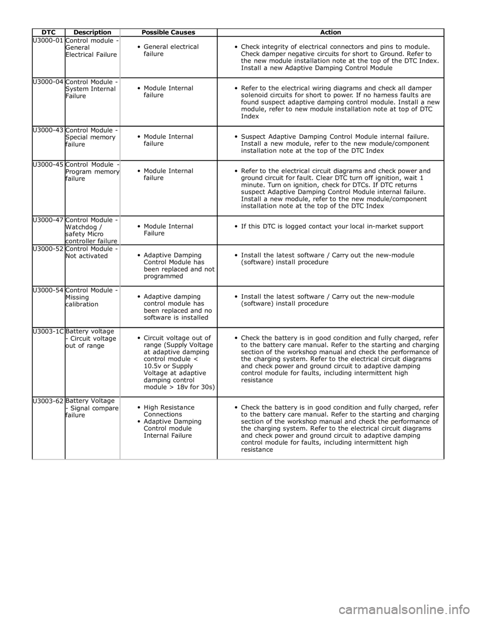
DTC Description Possible Causes Action U3000-01
Control module -
General
Electrical Failure
General electrical
failure
Check integrity of electrical connectors and pins to module.
Check damper negative circuits for short to Ground. Refer to
the new module installation note at the top of the DTC Index.
Install a new Adaptive Damping Control Module U3000-04
Control Module -
System Internal
Failure
Module Internal
failure
Refer to the electrical wiring diagrams and check all damper
solenoid circuits for short to power. If no harness faults are
found suspect adaptive damping control module. Install a new
module, refer to new module installation note at top of DTC
Index U3000-43
Control Module -
Special memory
failure
Module Internal
failure
Suspect Adaptive Damping Control Module internal failure.
Install a new module, refer to the new module/component
installation note at the top of the DTC Index U3000-45
Control Module -
Program memory
failure
Module Internal
failure
Refer to the electrical circuit diagrams and check power and
ground circuit for fault. Clear DTC turn off ignition, wait 1
minute. Turn on ignition, check for DTCs. If DTC returns
suspect Adaptive Damping Control Module internal failure.
Install a new module, refer to the new module/component
installation note at the top of the DTC Index U3000-47
Control Module -
Watchdog /
safety Micro
controller failure
Module Internal
Failure
If this DTC is logged contact your local in-market support U3000-52
Control Module -
Not activated
Adaptive Damping
Control Module has
been replaced and not
programmed
Install the latest software / Carry out the new-module
(software) install procedure U3000-54
Control Module -
Missing
calibration
Adaptive damping
control module has
been replaced and no
software is installed
Install the latest software / Carry out the new-module
(software) install procedure U3003-1C Battery voltage
- Circuit voltage
out of range
Circuit voltage out of
range (Supply Voltage
at adaptive damping
control module <
10.5v or Supply
Voltage at adaptive
damping control
module > 18v for 30s)
Check the battery is in good condition and fully charged, refer
to the battery care manual. Refer to the starting and charging
section of the workshop manual and check the performance of
the charging system. Refer to the electrical circuit diagrams
and check power and ground circuit to adaptive damping
control module for faults, including intermittent high
resistance U3003-62 Battery Voltage
- Signal compare
failure
High Resistance
Connections
Adaptive Damping
Control module
Internal Failure
Check the battery is in good condition and fully charged, refer
to the battery care manual. Refer to the starting and charging
section of the workshop manual and check the performance of
the charging system. Refer to the electrical circuit diagrams
and check power and ground circuit to adaptive damping
control module for faults, including intermittent high
resistance
Page 182 of 3039

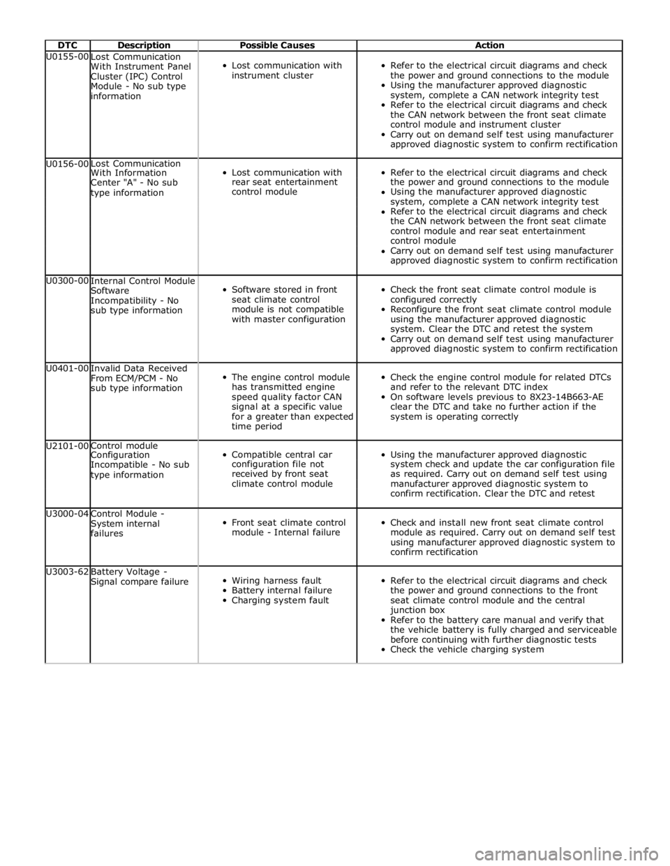
DTC Description Possible Causes Action U0155-00
Lost Communication
With Instrument Panel
Cluster (IPC) Control
Module - No sub type
information
Lost communication with
instrument cluster
Refer to the electrical circuit diagrams and check
the power and ground connections to the module
Using the manufacturer approved diagnostic
system, complete a CAN network integrity test
Refer to the electrical circuit diagrams and check
the CAN network between the front seat climate
control module and instrument cluster
Carry out on demand self test using manufacturer
approved diagnostic system to confirm rectification U0156-00 Lost Communication
Lost communication with
Refer to the electrical circuit diagrams and check With Information Center "A" - No sub rear seat entertainment the power and ground connections to the module type information control module Using the manufacturer approved diagnostic system, complete a CAN network integrity test Refer to the electrical circuit diagrams and check the CAN network between the front seat climate control module and rear seat entertainment control module Carry out on demand self test using manufacturer approved diagnostic system to confirm rectification U0300-00
Internal Control Module
Software
Incompatibility - No
sub type information
Software stored in front
seat climate control
module is not compatible
with master configuration
Check the front seat climate control module is
configured correctly
Reconfigure the front seat climate control module
using the manufacturer approved diagnostic
system. Clear the DTC and retest the system
Carry out on demand self test using manufacturer
approved diagnostic system to confirm rectification U0401-00
Invalid Data Received
From ECM/PCM - No
sub type information
The engine control module
has transmitted engine
speed quality factor CAN
signal at a specific value
for a greater than expected
time period
Check the engine control module for related DTCs
and refer to the relevant DTC index
On software levels previous to 8X23-14B663-AE
clear the DTC and take no further action if the
system is operating correctly U2101-00 Control module
Compatible central car
Using the manufacturer approved diagnostic Configuration Incompatible - No sub configuration file not system check and update the car configuration file type information received by front seat as required. Carry out on demand self test using climate control module manufacturer approved diagnostic system to confirm rectification. Clear the DTC and retest U3000-04
Control Module -
System internal
failures
Front seat climate control
module - Internal failure
Check and install new front seat climate control
module as required. Carry out on demand self test
using manufacturer approved diagnostic system to
confirm rectification U3003-62
Battery Voltage -
Signal compare failure
Wiring harness fault
Battery internal failure
Charging system fault
Refer to the electrical circuit diagrams and check
the power and ground connections to the front
seat climate control module and the central
junction box
Refer to the battery care manual and verify that
the vehicle battery is fully charged and serviceable
before continuing with further diagnostic tests
Check the vehicle charging system
Page 205 of 3039

DTC Description Possible Causes Action U3000-04
Control Module -
System Internal
Failures
Occupancy seat module
internal electronic failure
Check and install a new occupancy seat module as
required. Refer to the warranty policy and procedures
manual, or determine if any prior approval programme is
in operation, prior to the installation of a new
module/component U3000-54
Control Module -
Missing calibration
This diagnostic trouble
code is set if a 'calibrate
occupancy seat module
empty seat offset'
routine is requested and
fails due to one of the
pre-conditions to
execute the routine
Check the following criteria have all been achieved:
Ignition status set to RUN/START. Verify seat is always
empty after power-up before re-zero is requested. The
occupancy seat module has gone through the seat
assembly plant calibration. No collision event received
from the restraints control module during the current
ignition cycle. No faults present in the current ignition
cycle. The trigger message for calibrate empty seat
offset has been received from the diagnostic tool.
Occupancy seat module has enough time to begin
classification. Temperature is between 6C (42F) and 36C
(97F) U3003-16
Battery Voltage -
Circuit voltage
below threshold
Circuit voltage below
threshold
Check battery is in fully charged and serviceable
condition. Check integrity of charging system U3003-17
Battery Voltage -
Circuit voltage
above threshold
Circuit voltage above
threshold
Check battery is in fully charged and serviceable
condition. Check integrity of charging system
Page 237 of 3039

DTC Description Possible Causes Action B1A89-12
Satellite Antenna -
Circuit short to
battery
Satellite antenna circuit -
short to power
Refer to the electrical circuit diagrams and check
satellite antenna circuit for short circuit to power. Repair
wiring harness as required. Clear DTC and retest B1A89-13
Satellite Antenna -
Circuit open
Satellite antenna circuit -
open circuit, high
resistance
Refer to the electrical circuit diagrams and check
satellite antenna circuit for open circuit, high
resistance. Repair wiring harness as required. Clear DTC
and retest U3000-04
Control Module -
System internal
failures
System internal failure
Check and install a new satellite radio module as
required. Refer to the warranty policy and procedures
manual, or determine if any prior approval programme is
in operation, prior to the installation of a new
module/component U3000-4A Control Module -
Satellite radio module -
Using the manufacturer approved diagnostic system Incorrect component Incorrect component select the vehicle configuration main menu>vehicle installed installed configuration>display and modify the vehicle Car configuration configuration file data mismatch Check update as required U3000-55
Control Module -
Not configured
Satellite radio module -
Incorrect component
installed
Incorrect car configuration
file data received
Using the manufacturer approved diagnostic system
select the vehicle configuration main menu>select
configure existing modules menu and program the
satellite radio module U3000-87
Control Module -
Missing message
The satellite radio module
has not received the
configuration file
Master module not
transmitting configuration
file
Using the manufacturer approved diagnostic system
check that the satellite radio module is configured
correctly
Check that the configuration file is being transmitted by
the master module
Using the manufacturer approved diagnostic system,
complete a MOST network integrity test U3000-98
Control Module -
Component or
system over
temperature
Satellite radio module
cooling vents obstructed
Wiring harness fault
Internal electronic failure
Check for possible causes of the satellite radio module
overheating. Check that the ventilation is not
obstructed
Check for short circuit related DTCs. Refer to the
electrical circuit diagrams and check ground circuit for
high resistance. Check antenna circuit for short to power
or ground. Repair wiring harness as required. Clear DTC
and retest
Check for internal electronic failure related DTCs
If fault persists, check and install a new satellite radio
module. Refer to the warranty policy and procedures
manual, or determine if any prior approval programme is
in operation, prior to the installation of a new
module/component U3003-62
Battery Voltage -
Signal compare
failure
Signal compare failure
Satellite radio module
voltage differs more than
±2V compared to rear
junction box voltage
Refer to relevant section of workshop manual and
battery care manual. Check battery state of charge and
starting/charging system performance. Check power
supply circuit from rear junction box to satellite radio
module
Refer to electrical circuit diagrams and check the power
and ground supply circuits to the module. Repair wiring
harness as required. Clear DTC and retest
Page 274 of 3039

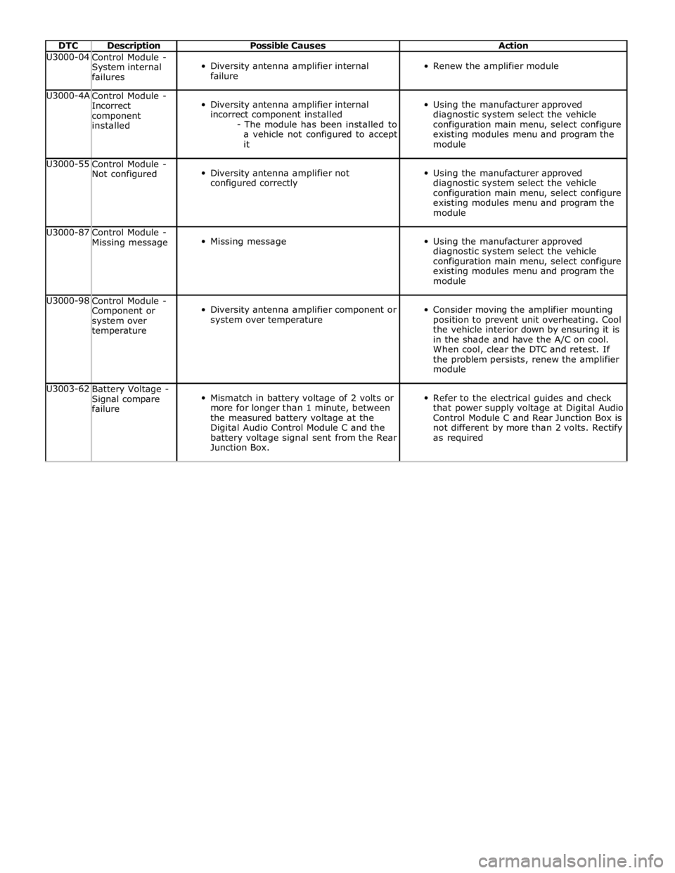
DTC Description Possible Causes Action U3000-04
Control Module -
System internal
failures
Diversity antenna amplifier internal
failure
Renew the amplifier module U3000-4A
Control Module -
Incorrect
component
installed
Diversity antenna amplifier internal
incorrect component installed
- The module has been installed to
a vehicle not configured to accept
it
Using the manufacturer approved
diagnostic system select the vehicle
configuration main menu, select configure
existing modules menu and program the
module U3000-55
Control Module -
Not configured
Diversity antenna amplifier not
configured correctly
Using the manufacturer approved
diagnostic system select the vehicle
configuration main menu, select configure
existing modules menu and program the
module U3000-87
Control Module -
Missing message
Missing message
Using the manufacturer approved
diagnostic system select the vehicle
configuration main menu, select configure
existing modules menu and program the
module U3000-98
Control Module -
Component or
system over
temperature
Diversity antenna amplifier component or
system over temperature
Consider moving the amplifier mounting
position to prevent unit overheating. Cool
the vehicle interior down by ensuring it is
in the shade and have the A/C on cool.
When cool, clear the DTC and retest. If
the problem persists, renew the amplifier
module U3003-62
Battery Voltage -
Signal compare
failure
Mismatch in battery voltage of 2 volts or
more for longer than 1 minute, between
the measured battery voltage at the
Digital Audio Control Module C and the
battery voltage signal sent from the Rear
Junction Box.
Refer to the electrical guides and check
that power supply voltage at Digital Audio
Control Module C and Rear Junction Box is
not different by more than 2 volts. Rectify
as required
Page 2353 of 3039

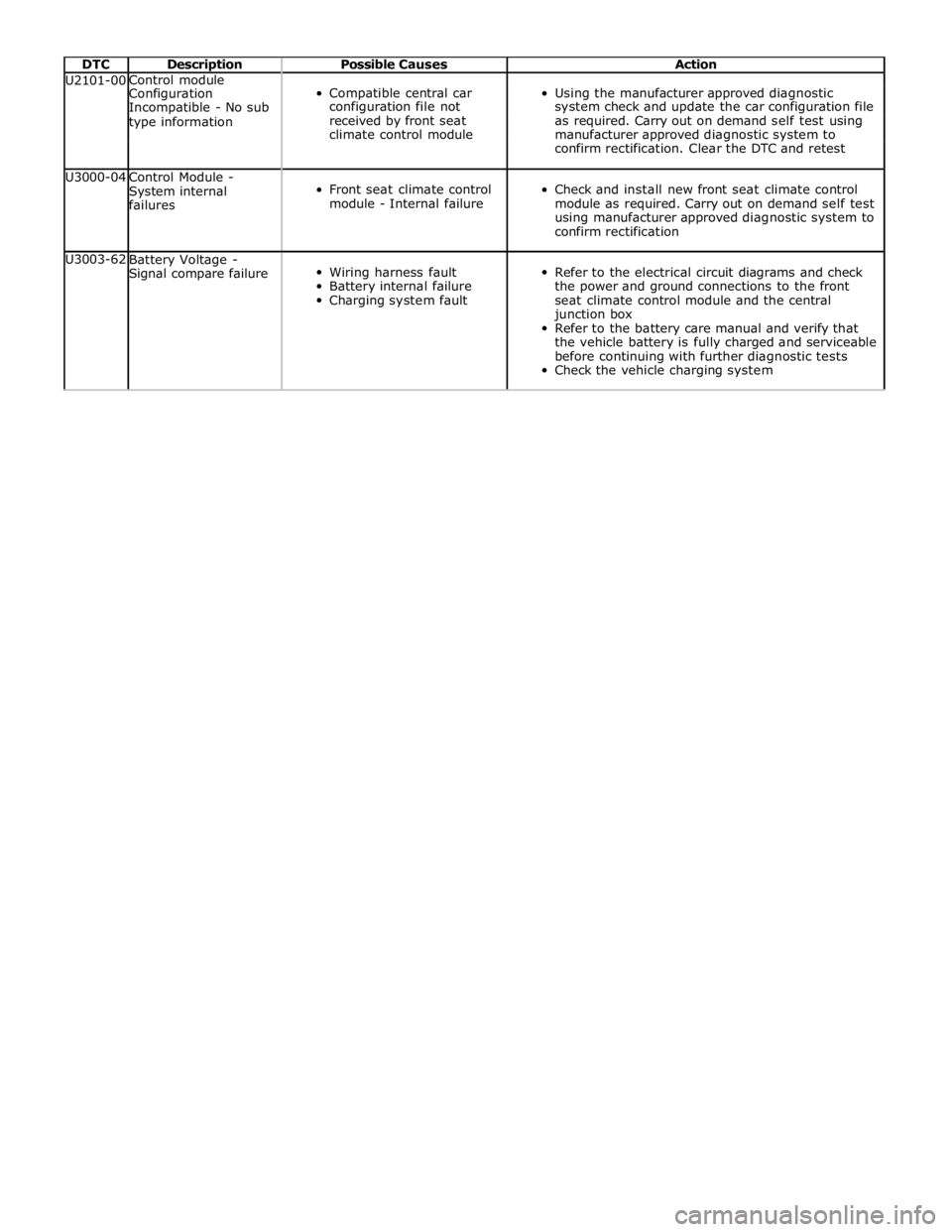
DTC Description Possible Causes Action U2101-00 Control module
Compatible central car
Using the manufacturer approved diagnostic Configuration Incompatible - No sub configuration file not system check and update the car configuration file type information received by front seat as required. Carry out on demand self test using climate control module manufacturer approved diagnostic system to confirm rectification. Clear the DTC and retest U3000-04
Control Module -
System internal
failures
Front seat climate control
module - Internal failure
Check and install new front seat climate control
module as required. Carry out on demand self test
using manufacturer approved diagnostic system to
confirm rectification U3003-62
Battery Voltage -
Signal compare failure
Wiring harness fault
Battery internal failure
Charging system fault
Refer to the electrical circuit diagrams and check
the power and ground connections to the front
seat climate control module and the central
junction box
Refer to the battery care manual and verify that
the vehicle battery is fully charged and serviceable
before continuing with further diagnostic tests
Check the vehicle charging system