washer fluid JAGUAR XFR 2010 1.G Workshop Manual
[x] Cancel search | Manufacturer: JAGUAR, Model Year: 2010, Model line: XFR, Model: JAGUAR XFR 2010 1.GPages: 3039, PDF Size: 58.49 MB
Page 191 of 3039

DTC Description Possible Causes Action B10A0-11
Wiper/ Washer Switch -
Circuit short to ground
Wash/wipe circuit - short to
ground
Refer to the electrical circuit diagrams and check
wash/wipe circuit for short to ground B10A0-15
Wiper/ Washer Switch -
Circuit short to battery
or open
Wash/wipe circuit - short to
power, open circuit
Carry out any pinpoint tests associated with this
DTC using the manufacturer approved diagnostic
system. Refer to the electrical circuit diagrams
and check wash/wipe circuit for short to power,
open circuit B10A6-11
Main Light Switch -
Circuit short to ground
Master lighting switch circuit
- short to ground
Refer to the electrical circuit diagrams and check
master lighting switch circuit for short to ground B10A6-15
Main Light Switch -
Circuit short to battery
or open
Master lighting switch circuit
- short to power, open
circuit
Carry out any pinpoint tests associated with this
DTC using the manufacturer approved diagnostic
system. Refer to the electrical circuit diagrams
and check master lighting switch circuit for short
to power, open circuit B112B-87
Steering Wheel Module -
Missing message
Steering wheel module
failure - slave node not
responding
Carry out any pinpoint tests associated with this
DTC using the manufacturer approved diagnostic
system. Refer to the electrical circuit diagrams
and check the clockspring LIN circuit for short,
open circuit. Suspect the clockspring, check and
install a new clockspring as required, refer to the
new module/component installation note at the
top of the DTC Index B115C-7A Transfer Fuel Pump -
Fluid leak or seal failure
Fuel pump system fault
Check for fuel system jet pump or jet pump fuel
level sensor fault B1A85-15
Ambient Light Sensor -
Circuit short to battery
or open
Autolamp sensor circuit -
short to power, open circuit
Carry out any pinpoint tests associated with this
DTC using the manufacturer approved diagnostic
system. Refer to the electrical circuit diagrams
and check autolamp sensor circuit for short to
power, open circuit B1B01-00
Key Transponder - No
sub type information
Operator only cycles one key
During transponder key
programming the instrument
cluster, smartcard docking
station or key loses
power/circuit failure
Faulty key during key
programming
Unable to program
transponder key due to
noise/EMC related error
Ensure all keys to be programmed are available.
Refer to electrical circuit diagrams and check
power and ground supply circuits to all relevant
modules. Replace faulty key and repeat key
programming. Check CAN network for
interference/EMC related issues B1B01-05
Key Transponder -
System programming
failures
Error following SCU
replacement
Smartcard docking station
power and ground supply
circuits - short, open circuit
LIN fault
Instrument cluster power
and ground supply circuits -
short, open circuit
Carry out any pinpoint tests associated with this
DTC using the manufacturer approved diagnostic
system. Perform the Immobilisation application
from the Set-up menu using the manufacturer
approved diagnostic system. Refer to the
electrical circuit diagrams and check smartcard
docking station power and ground supply circuits
for short, open circuit and instrument cluster
power and ground supply circuits for short, open
circuit. Check LIN communications between
smartcard docking station and instrument cluster B1B01-51
Key Transponder - Not
programmed
LIN fault
Instrument cluster power
and ground supply circuits -
short, open circuit
Key fault
Smartcard docking station
power and ground supply
circuits - short, open circuit
Attempted to program a non
Carry out any pinpoint tests associated with this
DTC using the manufacturer approved diagnostic
system. Check LIN communications between
smartcard docking station and instrument
cluster. Refer to the electrical circuit diagrams
and check smartcard docking station power and
ground supply circuits for short, open circuit and
instrument cluster power and ground supply
circuits for short, open circuit. Confirm www.JagDocs.com
Page 412 of 3039
Rear Suspension - Rear Stabilizer Bar
Removal and Installation Published: 06-Jun-2013
Removal
1. Disconnect the battery ground cable.
For additional information, refer to: Battery Disconnect and Connect (414-01 Battery, Mounting and Cables, General Procedures).
2. WARNING: Make sure to support the vehicle with axle stands.
Raise and support the vehicle.
3. Remove both rear wheels and tires.
For additional information, refer to: Wheel and Tire (204-04 Wheels and Tires, Removal and Installation).
4. Drain the fuel tank.
For additional information, refer to: Fuel Tank Draining (310-00 Fuel System - General Information, General Procedures).
5. Remove the exhaust system.
For additional information, refer to: Front Muffler (309-00B Exhaust System - V6 3.0L Petrol, Removal and Installation).
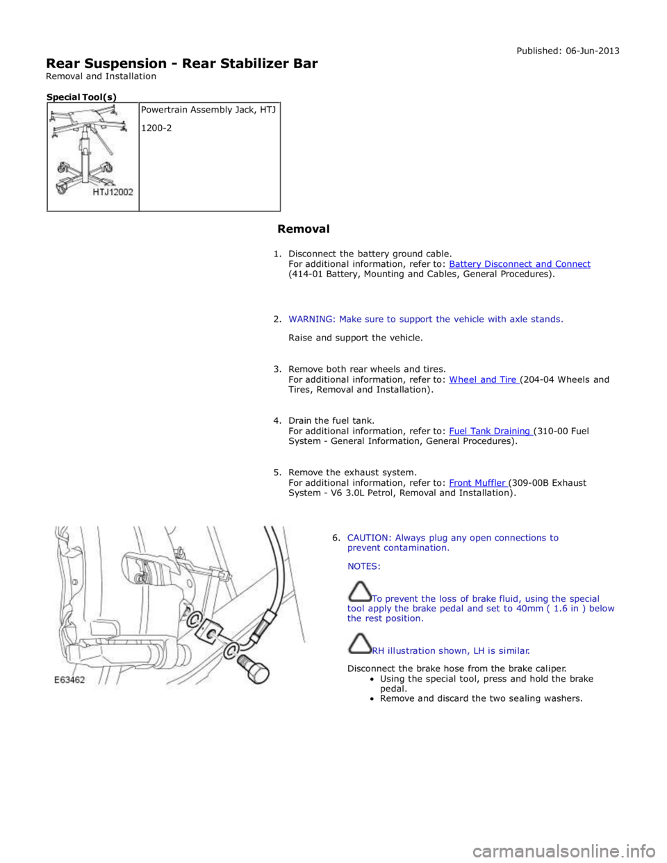
6. CAUTION: Always plug any open connections to
prevent contamination.
NOTES:
To prevent the loss of brake fluid, using the special
tool apply the brake pedal and set to 40mm ( 1.6 in ) below
the rest position.
RH illustration shown, LH is similar.
Disconnect the brake hose from the brake caliper.
Using the special tool, press and hold the brake
pedal.
Remove and discard the two sealing washers. Powertrain Assembly Jack, HTJ
1200-2 Special Tool(s)
Page 612 of 3039
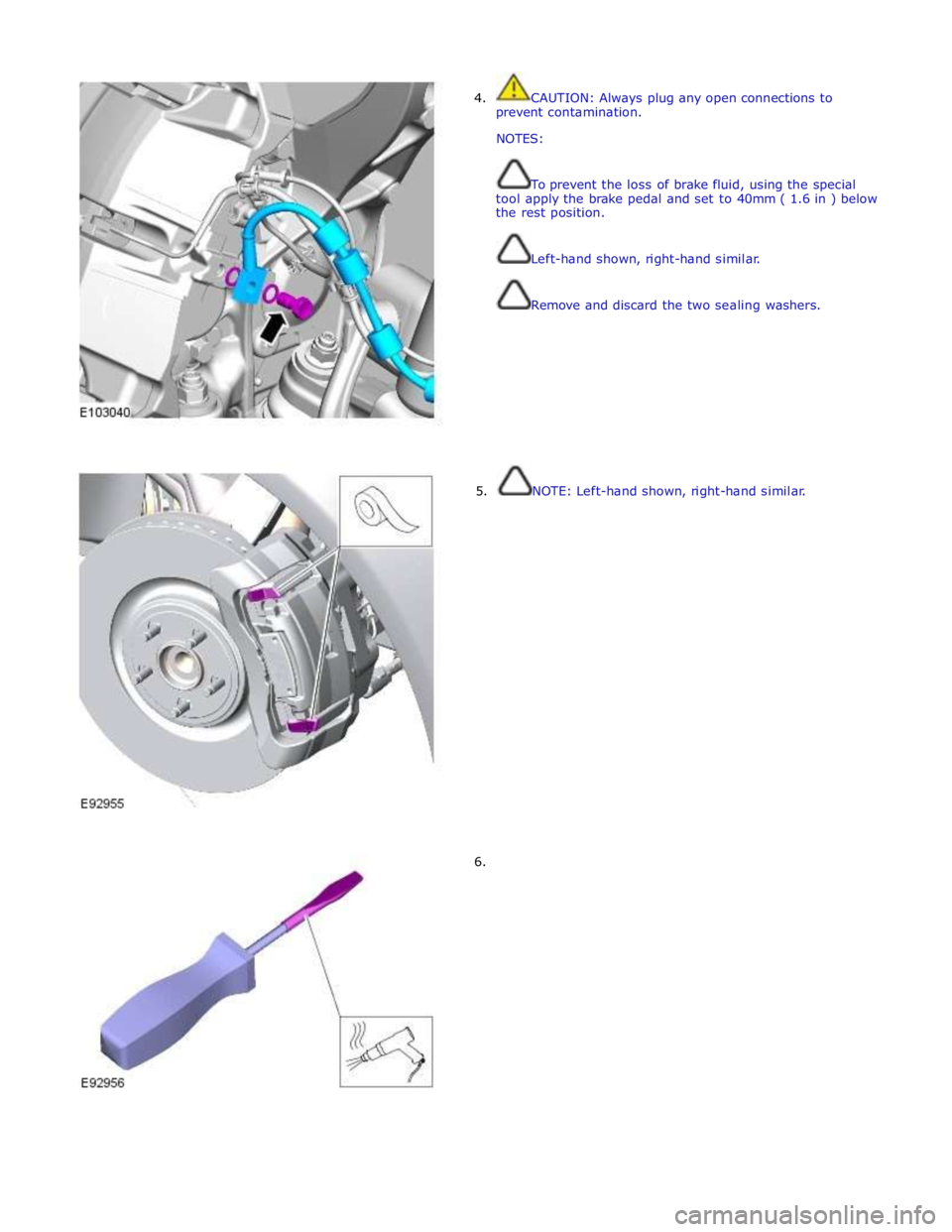
4. CAUTION: Always plug any open connections to
prevent contamination.
NOTES:
To prevent the loss of brake fluid, using the special
tool apply the brake pedal and set to 40mm ( 1.6 in ) below
the rest position.
Left-hand shown, right-hand similar.
Remove and discard the two sealing washers.
5. NOTE: Left-hand shown, right-hand similar.
6.
Page 616 of 3039
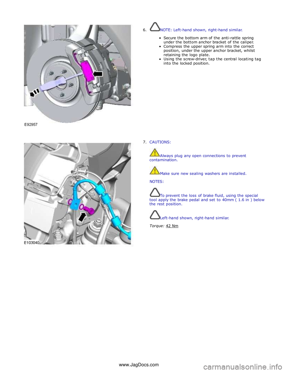
6. NOTE: Left-hand shown, right-hand similar.
Secure the bottom arm of the anti-rattle spring
under the bottom anchor bracket of the caliper.
Compress the upper spring arm into the correct
position, under the upper anchor bracket, whilst
retaining the logo plate.
Using the screw-driver, tap the central locating tag
into the locked position.
7. CAUTIONS:
Always plug any open connections to prevent
contamination.
Make sure new sealing washers are installed.
NOTES:
To prevent the loss of brake fluid, using the special
tool apply the brake pedal and set to 40mm ( 1.6 in ) below
the rest position.
Left-hand shown, right-hand similar.
Torque: 42 Nm www.JagDocs.com
Page 750 of 3039
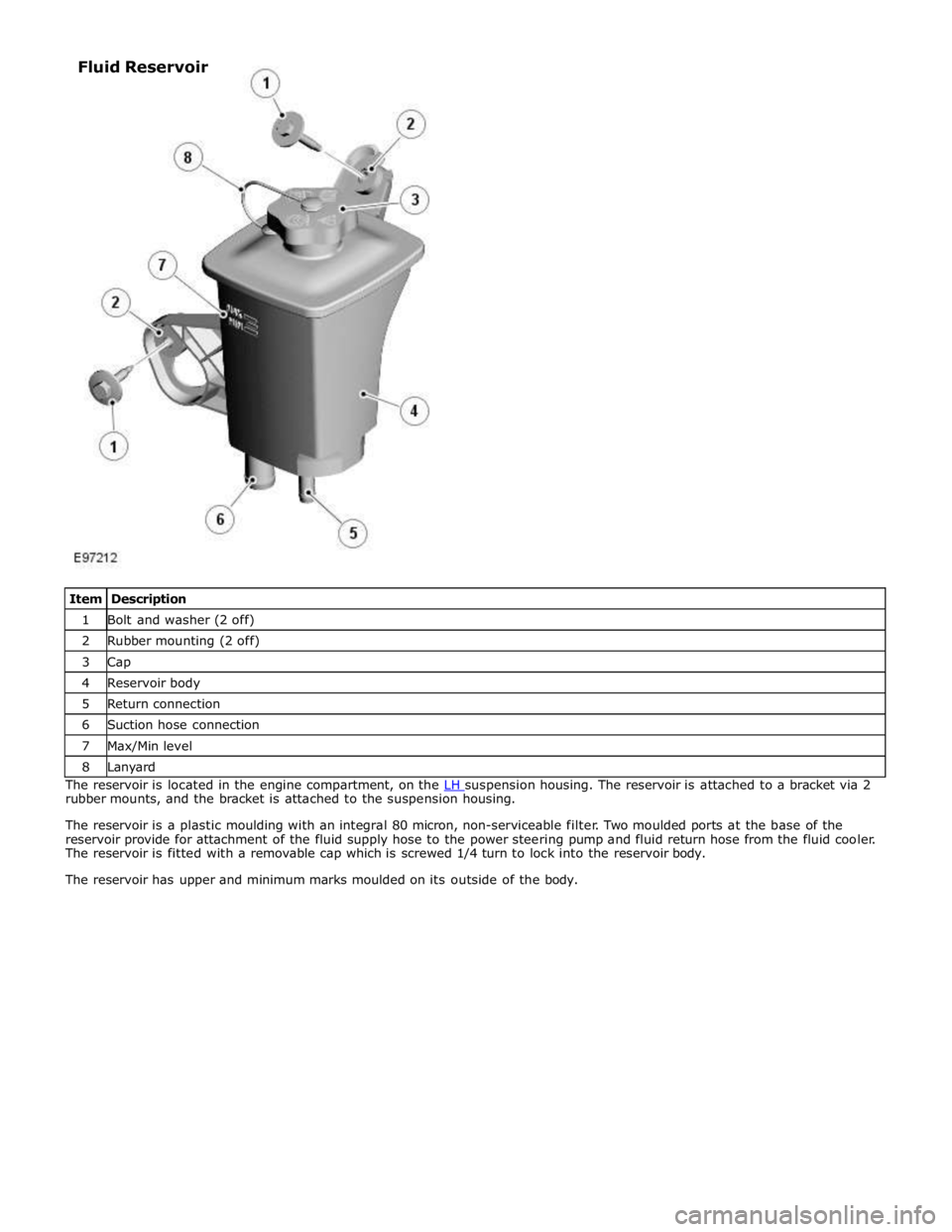
1 Bolt and washer (2 off) 2 Rubber mounting (2 off) 3 Cap 4 Reservoir body 5 Return connection 6 Suction hose connection 7 Max/Min level 8 Lanyard The reservoir is located in the engine compartment, on the LH suspension housing. The reservoir is attached to a bracket via 2 rubber mounts, and the bracket is attached to the suspension housing.
The reservoir is a plastic moulding with an integral 80 micron, non-serviceable filter. Two moulded ports at the base of the
reservoir provide for attachment of the fluid supply hose to the power steering pump and fluid return hose from the fluid cooler.
The reservoir is fitted with a removable cap which is screwed 1/4 turn to lock into the reservoir body.
The reservoir has upper and minimum marks moulded on its outside of the body. Fluid Reservoir
Page 764 of 3039
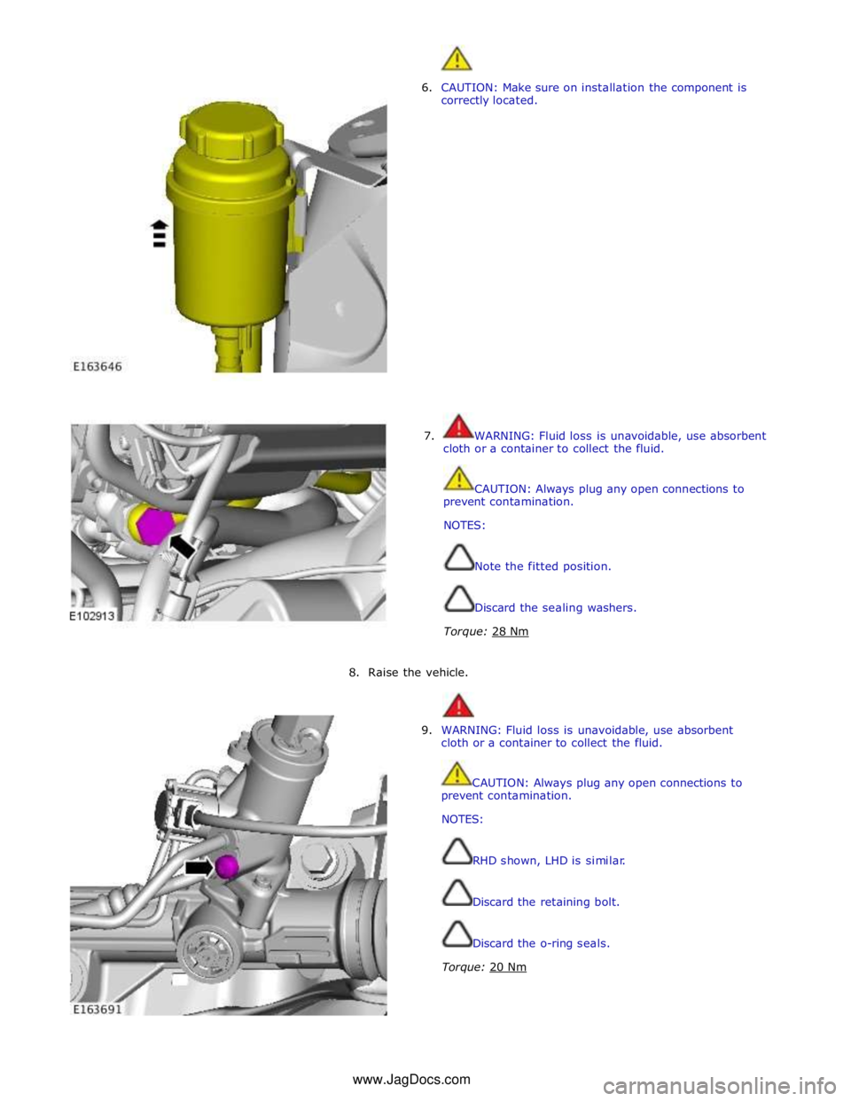
6. CAUTION: Make sure on installation the component is
correctly located.
7. WARNING: Fluid loss is unavoidable, use absorbent
cloth or a container to collect the fluid.
CAUTION: Always plug any open connections to
prevent contamination.
NOTES:
Note the fitted position.
Discard the sealing washers.
Torque: 28 Nm
8. Raise the vehicle.
9. WARNING: Fluid loss is unavoidable, use absorbent
cloth or a container to collect the fluid.
CAUTION: Always plug any open connections to
prevent contamination.
NOTES:
RHD shown, LHD is similar.
Discard the retaining bolt.
Discard the o-ring seals.
Torque: 20 Nm www.JagDocs.com
Page 1430 of 3039

1 Securing ring 2 Shaft oil seal 3 O-ring seal 4 Pump housing 5 Ring gear 6 Crescent spacer 7 Roller bearing 8 Impeller 9 Centering pin 10 Spring washer 11 Outlet port (high pressure) 12 Inlet port (low pressure) The pump comprises a housing, a crescent spacer, an impeller and a ring gear. The housing has inlet and outlet ports to direct
flow and is located in the intermediate plate by a centering pin. The pump action is achieved by the impeller, ring gear and
crescent spacer.
The crescent spacer is fixed in its position by a pin and is located between the ring gear and the impeller. The impeller is
driven by drive from the torque converter hub which is located on a needle roller bearing in the pump housing. The impeller
teeth mesh with those of the ring gear. When the impeller is rotated, the motion is transferred to the ring gear which rotates
in the same direction.
The rotational motion of the ring gear and the impeller collects fluid from the intake port in the spaces between the teeth.
When the teeth reach the crescent spacer, the oil is trapped in the spaces between the teeth and is carried with the rotation
of the gears. The spacer tapers near the outlet port. This reduces the space between the gear teeth causing a build up of fluid
pressure as the oil reaches the outlet port. When the teeth pass the end of the spacer the pressurized fluid is released into
the outlet port.
The fluid emerging from the outlet port is passed through the fluid pressure control valve. At high operating speeds the
pressure control valve maintains the output pressure to the gearbox at a predetermined maximum level. Excess fluid is
relieved from the pressure control valve and is directed, via the main pressure valve in the valve block, back to the pump inlet
port. This provides a pressurized feed to the pump inlet which prevents cavitation and reduces pump noise.
Page 1451 of 3039
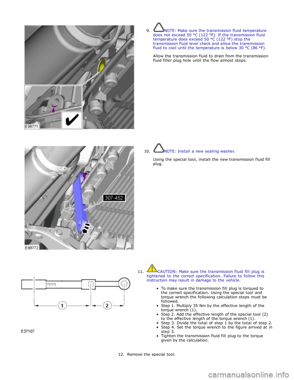
9.
10. NOTE: Make sure the transmission fluid temperature
does not exceed 50 °C (122 °F). If the transmission fluid
temperature does exceed 50 °C (122 °F) stop the
transmission fluid level check and allow the transmission
fluid to cool until the temperature is below 30 °C (86 °F).
Allow the transmission fluid to drain from the transmission
fluid filler plug hole until the flow almost stops.
NOTE: Install a new sealing washer.
Using the special tool, install the new transmission fluid fill
plug.
11. CAUTION: Make sure the transmission fluid fill plug is
tightened to the correct specification. Failure to follow this
instruction may result in damage to the vehicle.
To make sure the transmission fill plug is torqued to
the correct specification. Using the special tool and
torque wrench the following calculation steps must be
followed.
Step 1. Multiply 35 Nm by the effective length of the
torque wrench (1).
Step 2. Add the effective length of the special tool (2)
to the effective length of the torque wrench (1).
Step 3. Divide the total of step 1 by the total of step 2.
Step 4. Set the torque wrench to the figure arrived at in
step 3.
Tighten the transmission fluid fill plug to the torque
given by the calculation.
12. Remove the special tool.
Page 1455 of 3039
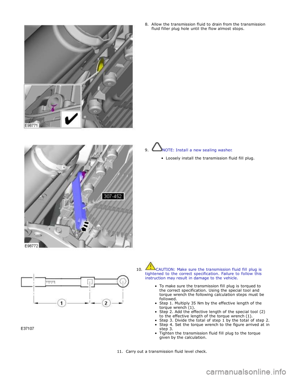
8. Allow the transmission fluid to drain from the transmission
fluid filler plug hole until the flow almost stops.
9. NOTE: Install a new sealing washer.
Loosely install the transmission fluid fill plug.
10. CAUTION: Make sure the transmission fluid fill plug is
tightened to the correct specification. Failure to follow this
instruction may result in damage to the vehicle.
To make sure the transmission fill plug is torqued to
the correct specification. Using the special tool and
torque wrench the following calculation steps must be
followed.
Step 1. Multiply 35 Nm by the effective length of the
torque wrench (1).
Step 2. Add the effective length of the special tool (2)
to the effective length of the torque wrench (1).
Step 3. Divide the total of step 1 by the total of step 2.
Step 4. Set the torque wrench to the figure arrived at in
step 3.
Tighten the transmission fluid fill plug to the torque
given by the calculation.
11. Carry out a transmission fluid level check.
Page 1800 of 3039

DTC Description Possible Cause Action B100D96
Column Lock
Authorisation -
Component
internal failure
Battery voltage at electric
steering column lock control
module too low
Torque load on steering
column
CAN fault
Electric steering column lock
control module - Internal
failure
Clear DTC, repeatedly lock and unlock car using the
key fob and retest
If fault persists, check that the vehicle battery supply
voltage is between 9-16 volts. Rectify as required
Ensure the column lock bolt movement is not
obstructed or restricted (the parked position of the
road wheels may be exerting a turning force through
the steering column, preventing the lock from
releasing. The steering wheel may need to be held
against the force to allow the column lock to
release). Clear DTC, repeatedly lock and unlock car
using the key fob and retest
If fault persists, complete a CAN network integrity
test using the manufacturers approved diagnostic
system. Alternatively, refer to the electrical circuit
diagrams and check CAN circuits between the central
junction box, the instrument cluster and the
electronic steering column lock. Refer to the electrical
circuit diagrams and check the central junction box,
the instrument cluster and the electronic steering
column lock power and ground supply circuits for short
circuit to ground, short circuit to power, open circuit,
high resistance. Repair circuit(s) as required. Clear
DTC, perform an on demand self-test and retest
If fault persists, check and install a new electric
steering column lock control module as required B102487 Start Control Unit
Smart card docking station
failure - slave node not
responding Carry out any pinpoint tests associated with this DTC using
the manufacturer approved diagnostic system. Refer to the
electrical circuit diagrams and check the smart card docking
station LIN circuit for short, open circuit. Suspect the smart
card docking station, check and install a new docking station
as required, refer to the new module/component installation
note at the top of the DTC Index B104611
Front Fog Lamp
Control Switch
Fog lamp switch circuit - short
to ground Refer to the electrical circuit diagrams and check fog lamp
switch circuit for short to ground B104615
Front Fog Lamp
Control Switch
Fog lamp switch circuit - short
to power, open circuit Refer to the electrical circuit diagrams and check fog lamp
switch circuit for short to power, open circuit B104811
Brake Fluid Level
Switch
Brake fluid level switch circuit
- short to ground Refer to the electrical circuit diagrams and check brake fluid
level switch circuit for short to ground B10A011
Wiper/ Washer
Switch
Wash/wipe circuit - short to
ground Refer to the electrical circuit diagrams and check wash/wipe
circuit for short to ground B10A015
Wiper/ Washer
Switch
Wash/wipe circuit - short to
power, open circuit Carry out any pinpoint tests associated with this DTC using
the manufacturer approved diagnostic system. Refer to the
electrical circuit diagrams and check wash/wipe circuit for
short to power, open circuit B10A611 Main Light Switch
Master lighting switch circuit -
short to ground Refer to the electrical circuit diagrams and check master
lighting switch circuit for short to ground B10A615 Main Light Switch
Master lighting switch circuit -
short to power, open circuit Carry out any pinpoint tests associated with this DTC using
the manufacturer approved diagnostic system. Refer to the
electrical circuit diagrams and check master lighting switch
circuit for short to power, open circuit B112B87
Steering Wheel
Module
Steering wheel module failure
- slave node not responding Carry out any pinpoint tests associated with this DTC using
the manufacturer approved diagnostic system. Refer to the
electrical circuit diagrams and check the clockspring LIN
circuit for short, open circuit. Suspect the clockspring, check
and install a new clockspring as required, refer to the new
module/component installation note at the top of the DTC
Index B115C7A
Transfer Fuel
Pump
Fuel pump system fault Check for fuel system jet pump or jet pump fuel level sensor
fault B1A8515
Ambient Light
Sensor
Autolamp sensor circuit - short
to power, open circuit Carry out any pinpoint tests associated with this DTC using
the manufacturer approved diagnostic system. Refer to the
electrical circuit diagrams and check autolamp sensor circuit
for short to power, open circuit