engine JAGUAR XJ 1994 2.G AJ16 Engine Manual
[x] Cancel search | Manufacturer: JAGUAR, Model Year: 1994, Model line: XJ, Model: JAGUAR XJ 1994 2.GPages: 73, PDF Size: 2.06 MB
Page 22 of 73
AJ16 Engine Service Manual
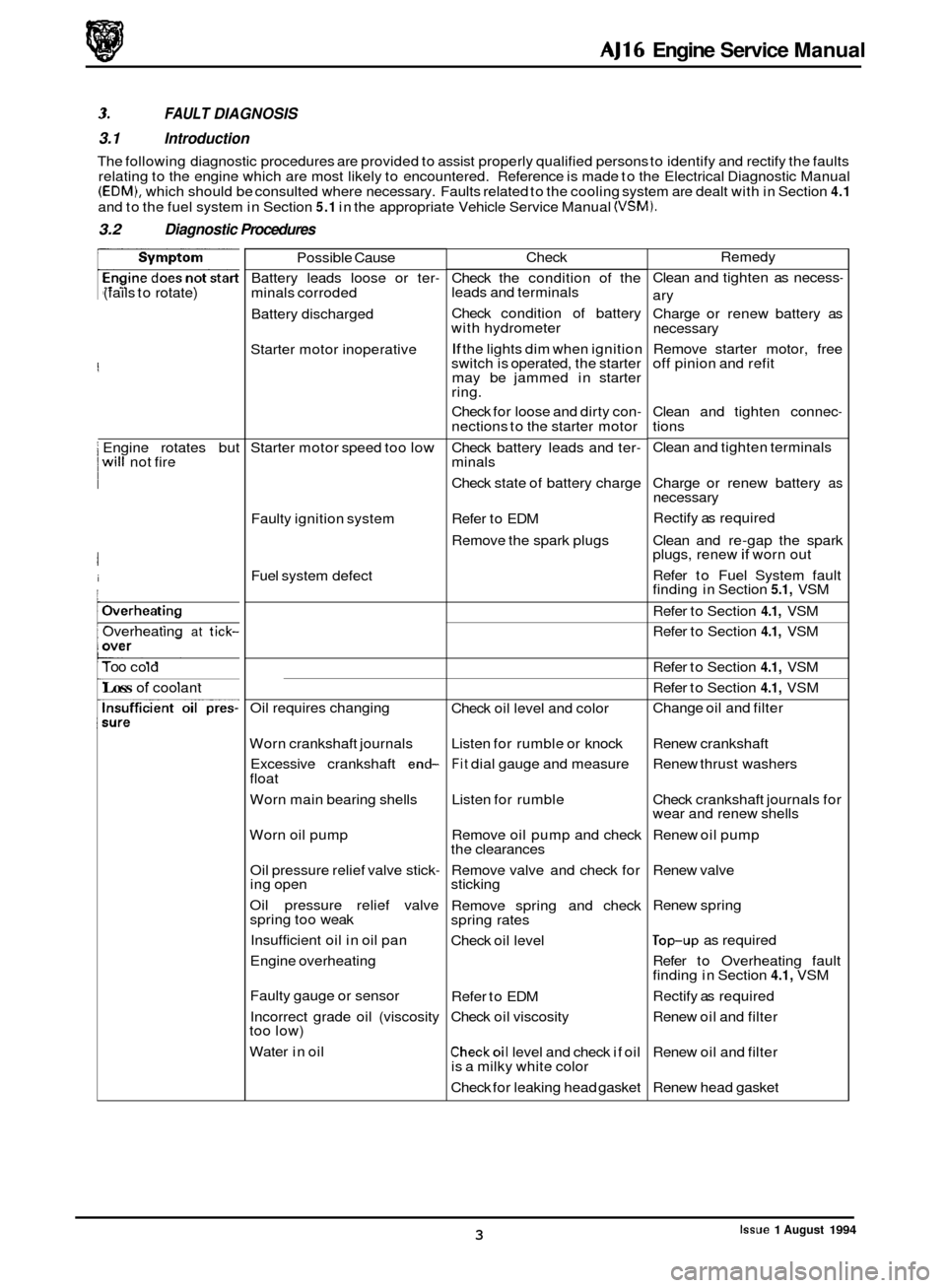
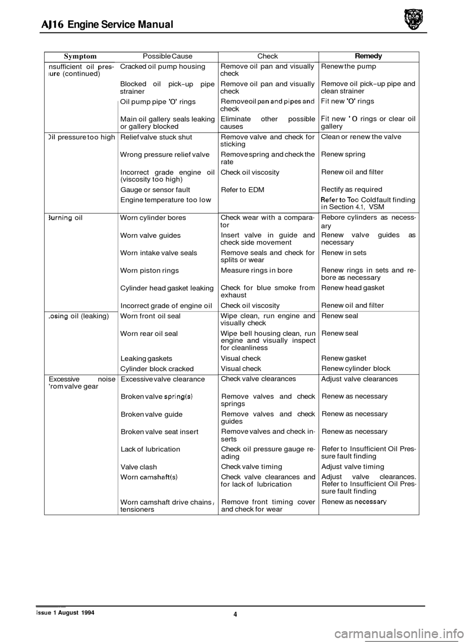
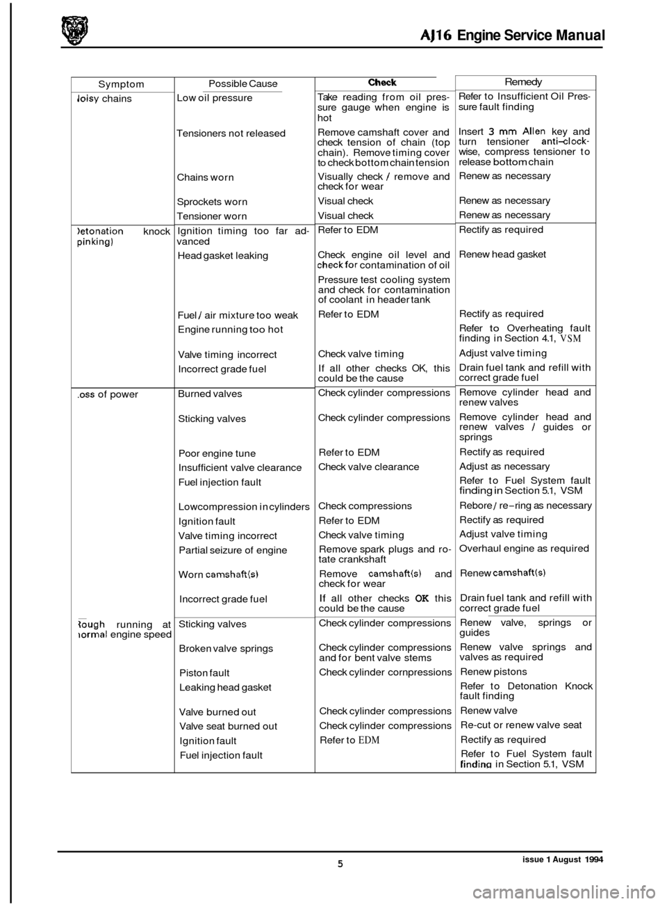
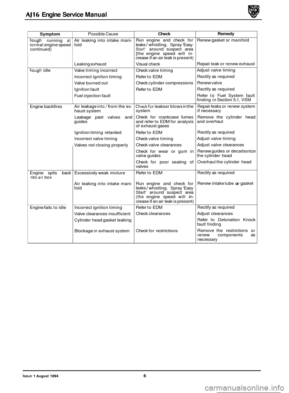
FAULT DIAGNOSIS
3.1 Introduction
The following diagnostic procedures are provided to assist properly qualified persons to identify and rectify the faults
relating to the engine which are most likely to encountered. Reference is made to the Electrical Diagnostic Manual
(EDM), which should be consulted where necessary. Faults related to the cooling system are dealt with in Section 4.1
and to the fuel system in Section 5.1 in the appropriate Vehicle Service Manual (VSM).
3.2 Diagnostic Procedures
(fails to rotate)
I Engine rotates but 0 I will not fire
I
i
/Overheating
Overheating at tick-
Too cold
Loss of coolant Possible
Cause
Battery leads loose or ter
- minals corroded
Battery discharged
Starter motor inoperative
Starter motor speed too
low
Faulty ignition system
Fuel system defect
Oil requires changing
Worn crankshaft journals
Excessive crankshaft
end- float
Worn main bearing shells
Worn oil pump Oil pressure relief valve stick
- ing open
Oil pressure relief valve
spring too weak
Insufficient oil in oil pan
Engine overheating
Faulty gauge or sensor
Incorrect grade oil (viscosity
too low)
Water in oil Check
Check the condition of the
leads and terminals
Check condition of battery
with hydrometer
If the lights dim when ignition
switch is operated, the starter
may be jammed in starter
ring.
Check for loose and dirty con
- nections to the starter motor
Check battery leads and ter
- minals
Check state of battery charge
Refer to EDM
Remove the spark plugs
Check oil level and color
Listen for rumble or knock
Fit dial gauge and measure
Listen for rumble
Remove oil pump and check
the clearances
Remove valve and check for
sticking
Remove spring and check
spring rates
Check oil level
Refer to EDM
Check oil viscosity
Checkoil level and check if oil
is a milky white color
Check for leaking head gasket Remedy
Clean and tighten as necess
-
ary
Charge or renew battery as
necessary
Remove starter motor, free
off pinion and refit
Clean and tighten connec
- tions
Clean and tighten terminals
Charge or renew battery
as necessary
Rectify as required
Clean and re
-gap the spark
plugs, renew if worn out
Refer to Fuel System fault
finding in Section
5.1, VSM
Refer to Section
4.1, VSM
Refer to Section
4.1, VSM
Refer to Section
4.1, VSM
Refer to Section
4.1, VSM
Change oil and filter
Renew crankshaft
Renew thrust washers
Check crankshaft journals for
wear and renew shells
Renew oil pump
Renew valve
Renew spring
lop-up as required
Refer to Overheating fault
finding in Section
4.1, VSM
Rectify as required
Renew oil and filter
Renew oil and filter
Renew head gasket
Issue 1 August 1994 3
Page 23 of 73
AJ16 Engine Service Manual
Symptom Possible Cause ~~
nsufficient
oil pres- ure (continued)
lil pressure too high
3urning oil
.osing oil (leaking)
Excessive noise
'rom valve gear Cracked
oil pump housing
Blocked oil pick
-up pipe
strainer
Oil pump pipe
'0' rings
Main oil gallery seals leaking
or gallery blocked
Relief valve stuck shut
Wrong pressure relief valve
Incorrect grade engine oil
(viscosity too high)
Gauge or sensor fault
Engine temperature too low
Worn cylinder bores
Worn valve guides
Worn intake valve seals
Worn piston rings
Cylinder head gasket leaking
Incorrect grade of engine oil
Worn front oil seal
Worn rear oil seal
Leaking gaskets
Cylinder block cracked
Excessive valve clearance
Broken valve
spring(s)
Broken valve guide
Broken valve seat insert
Lack of lubrication
Valve clash
Worn
camshaft(s)
Worn camshaft drive chains i tensioners
Check
Remove oil pan and visually
check
Remove oil pan and visually
check
Removeoil
panand pipesand check Eliminate other possible
causes
Remove valve and check for
sticking
Remove spring and check the
rate
Check oil viscosity
Refer to EDM
Check wear with
a compara- tor
Insert valve in guide and
check side movement
Remove seals and check for
splits or wear
Measure rings in bore
Check for blue smoke from
exhaust
Check oil viscosity
Wipe clean, run engine and
visually check
Wipe bell housing clean, run
engine and visually inspect
for cleanliness
Visual check
Visual check
Check valve clearances
Remove valves and check
springs
Remove valves and check
guides
Remove valves and check in
- serts
Check oil pressure gauge re
- ading
Check valve timing
Check valve clearances and
for lack
of lubrication
Remove front timing cover
and check for wear
Remedy
Renew the pump
Remove oil pick
-up pipe and
clean strainer
Fit new '0' rings
Fit new '0 rings or clear oil
gallery
Clean or renew the valve
Renew spring
Renew oil and filter
Rectify as required
RefertoToo Cold fault finding
in Section 4.1, VSM
Rebore cylinders as necess
-
ary
Renew valve guides as
necessary
Renew in sets
Renew rings in sets and re
- bore as necessary
Renew head gasket
Renew oil and filter
Renew seal
Renew seal
Renew gasket Renew cylinder block
Adjust valve clearances
Renew as necessary
Renew as necessary
Renew as necessary
Refer to Insufficient Oil Pres
- sure fault finding
Adjust valve timing
Adjust valve clearances.
Refer to Insufficient Oil Pres
- sure fault finding
Renew as
necessaw
0
0
0 ~~~
Issue 1 August 1994 4
Page 24 of 73
AJ16 Engine Service Manual
Symptom
Joisy chains
)etonation knock pinking)
.oss of power
Gugh running at iormal engine speed Possible
Cause
Low oil pressure
Tensioners not released
Chains worn
Sprockets worn
Tensioner worn
Ignition timing too far ad
- vanced
Head gasket leaking
Fuel
/ air mixture too weak
Engine running
too hot
Valve timing incorrect
Incorrect grade fuel
Burned valves Sticking valves
Poor engine tune
Insufficient valve clearance
Fuel injection fault
Lowcompression in cylinders
Ignition fault
Valve timing incorrect
Partial seizure of engine
Worn
camshaftb)
Incorrect grade fuel
Sticking valves Broken valve springs Piston fault
Leaking head gasket
Valve burned out
Valve seat burned out
Ignition fault
Fuel injection fault
Check
Take reading from oil pres- sure gauge when engine is
hot
Remove camshaft cover and
check tension of chain (top
chain). Remove timing cover
to check bottom chain tension
Visually check
/ remove and
check for wear
Visual check
Visual check
Refer to EDM
Check engine oil level and
checkfor contamination of oil
Pressure test cooling system
and check for contamination
of coolant in header tank
Refer to EDM
Check valve timing
If all other checks
OK, this
could be the cause
Check cylinder compressions
Check cylinder compressions
Refer to EDM
Check valve clearance
Check compressions
Refer to EDM
Check valve timing
Remove spark plugs and ro
- tate crankshaft
Remove
camshaft(s) and
check for wear
If all other checks OK this
could be the cause
Check cylinder compressions
Check cylinder compressions
and for bent valve stems
Check cylinder cornpressions
Check cylinder compressions
Check cylinder compressions
Refer to
EDM
Remedy
Refer to Insufficient Oil Pres- sure fault finding
Insert
3 mm Allen key and
turn tensioner anti-clock- wise, compress tensioner to
release bottom chain
Renew as necessary
Renew as necessary
Renew as necessary
Rectify as required
Renew head gasket
Rectify
as required
Refer
to Overheating fault
finding in Section 4.1, VSM
Adjust valve timing
Drain fuel tank and refill with
correct grade fuel
Remove cylinder head and
renew valves
Remove cylinder head and
renew valves
/ guides or
springs
Rectify as required
Adjust as necessary
Refer to Fuel System fault
finding in Section 5.1, VSM
Rebore
1 re-ring as necessary
Rectify as required
Adjust valve timing
Overhaul engine as required
Renew
camshaft(s)
Drain fuel tank and refill with
correct grade fuel
Renew valve, springs or
guides
Renew valve springs and
valves as required
Renew pistons
Refer to Detonation Knock
fault finding
Renew valve
Re
-cut or renew valve seat
Rectify as required
Refer to Fuel System fault
Tindim in Section 5.1, VSM
issue 1 August 1994 5
Page 25 of 73
AJ16 Engine Service Manual
Symptom
3ough running at iormal engine speed
continued)
3ough idle
Engine backfires
Engine spits back
nto
air box
Engine fails to idle
Possible Cause
Air leaking into intake mani- fold
Leaking exhaust
Valve timing incorrect
Incorrect ignition timing
Valve burned out
Ignition fault
Fuel injection fault
Air leakage
intolfrom the ex- haust system
Leakage past valves and
guides
Ignition timing retarded
Incorrect valve timing
Valves not closing properly
Excessively weak mixture
Air leaking into intake mani
- fold
Incorrect ignition timing
Valve clearances insufficient
Cylinder head gasket leaking
Blockage in exhaust system
Check
Run engine and check for
leaks / whistling. Spray 'Easy Start' around suspect area
[the engine speed will in- crease if an air leak is present)
Visual check
Check valve timing
Refer to EDM
Check cylinder compressions
Refer to EDM
Checkfor leaksor blows in the
system
Check for crankcase fumes
and refer to EDM for analysis
of exhaust gases
Refer to EDM
Check valve timing
Check valve clearances
Check for wear or gum in
valve guides
Check for poor seating of
valves
Refer to EDM
Run engine and check for
leaks
/ whistling. Spray 'Easy
Start' around suspect area
(the engine speed will in- crease if an air leak is present)
Refer to EDM
Check clearances
Check for restrictions
Remedy
Renew gasket or manifold
Repair leak or renew exhaust
Adjust valve timing
Rectify as required
Renew valve
Rectify as required
Refer to Fuel System fault
finding in Section
5.1, VSM
Repair leaks or renew system if necessary
Remove the cylinder head
and overhaul
Rectify as required
Adjust valve timing
Adjust valve clearances
Renew guides or decarbonize
the cylinder head
Overhaul the cylinder head
Rectify as required
Renew intake tube
or gasket
Rectify as required
Adjust clearances
Refer to Detonation Knock
fault finding
Remove the restrictions or
renew components as
necessary
Issue 1 August 1994 6
Page 26 of 73

AJ16 Engine Service Manual
SERVICE OPERATIONS
4.1 Camshaft, Renew
SRO 12.13.01
Remove camshaft cover, see Section 4.2.
Drain the cooling system, see Section 4.1 in the appropri
- ate Vehicle Service Manual.
1 Rotate the engine and set No. 1 cylinder at TDC using Ser- viceTool 18G 1433 (1 Fig. 1).
Push back the lock tabs (1 Fig.2) from the camshaft
sprocket securing bolts (2 Fig. 2). and slacken off the bolts.
Remove the upper chain tensioner valve clamp bolt
(3 Fig.
2), remove the clamp (4 Fig. 2) and remove the
valve (5 Fig. 2).
1 Using a 3 mm Allen key, wind backthe tensioner (6 Fig. 2) (turn clockwise) until the snail engages in the park posi- tion. Remove the tensioner housing securing bolt (7 Fig. 2) and withdraw the tensioner assembly (8, 9 Fig. 2).
1 Remove and discard the '0' ring (9 Fig. 2) and gasket (10 Fig. 2).
. Remove the camshaft sprocket securing bolts and tab
washers (1,2 Fig. 2) and remove the sprockets (11 Fig. 2) (ensure that neither the bolts nor the tab washer drop into
the timing case).
CAUTION: Do not rotate the engine while the camshaft is
disconnected.
. Remove the cylinder head bolt from No. 2 cap, left-hand
1 Remove No. 2 cap from the left-hand camshaft.
1 Fit spacer tool 18G 1435 (2 Fig. 3) to the head.
Fit and torque tighten the cylinder head bolt.
Repeat the procedure for Nos 3,4,5 and 6 caps, left-hand
camshaft (3 Fig. 3).
Remove the cylinder head bolt from
No. 7 cap, left-hand
camshaft.
Loosen in sequence the securing bolts from Nos 1 and 7 caps, until theleft-handcamshaft isfree. Liftthecamshaft
from the cylinder head and fit spacer tool 18G 1435 to No. 7 cylinder head bolt position (5 Fig. 3). Fit and torque
tighten the bolt.
Clean
all components and examine for wear and damage.
Renew all worn or damaged components.
Lubricate the new left
-hand camshaft.
Fit the camshaft at approximately TDC.
Lubricate Nos 1 and 7 caps.
Fit No. 1 cap but do not tighten the securing bolts. Remove No. 7 cap cylinder head bolt.
1 Remove the spacer tool. Fit No. 7 cap but do not tighten
the securing bolts.
1 Finally tighten Nos 1 and 7 cap securing bolts in sequence.
Remove No. 4 cap cylinder head bolt and remove the
spacer tool. Lubricate and fit No. 4 cap.
CAUTION: The cylinder head bolts MUST be renewed dur- ing assembly and torque tightened as de- scribed in Section 2.1, SPS Joint Control System.
camshaft
(1 Fig. 3).
1 Repeat
the procedure for the right-hand camshaft.
1
Fia. 1
Fia. 2
Fig. 3
Issue 1 August 1994 7
Page 27 of 73
AJ16 Engine Service Manual
. Fit and tighten No. 4 cap securing bolts.
. Fit and tighten No. 4 cap cylinder head bolt.
CAUTION: The cylinder head bolts MUST be renewed dur- ing assembly and torque tightened as de- scribed in Section 2.1, SPS Joint Control
System.
. Repeat the procedure for Nos 2,3,5 and 6 caps, left-hand
Set the left-hand camshaft to TDC.
. Repeat the procedure for the right-hand camshaft.
. Check and adjust valve clearances see Section 4.3.
Refit the camshaft cover, see Section 4.2.
camshaft. ~~
Issue 1 August 1994 8
Page 28 of 73

AJ16 Engine Service Manual
4.2 Camshaft Cover Gasket, Renew
SRO 12.29.39
1 Remove the top cover and disconnect the on-plug coils
from the spark plugs.
. Disconnect the camshaft cover breather hose.
1 Remove the camshaft cover to cylinder head securing
Screws (1 Fig. 11, and remove the camshaft cover (2 Fig. 1).
. Remove and discard the camshaft cover gasket (3 Fig. 1).
. Clean the camshaft cover and cylinder head mating faces.
1 Fit a new gasket to the camshaft cover.
. Refit the camshaft cover.
1 Fit and tighten the camshaft cover securing screws.
. Reconnect the breather hose.
1 Reconnect the on-plug coils to the spark plugs and fit the
top cover.
I Fia. I
Issue 1 August 1994 9
Page 29 of 73
AJ16 Engine Service Manual
4.3
SRO 12.29.48
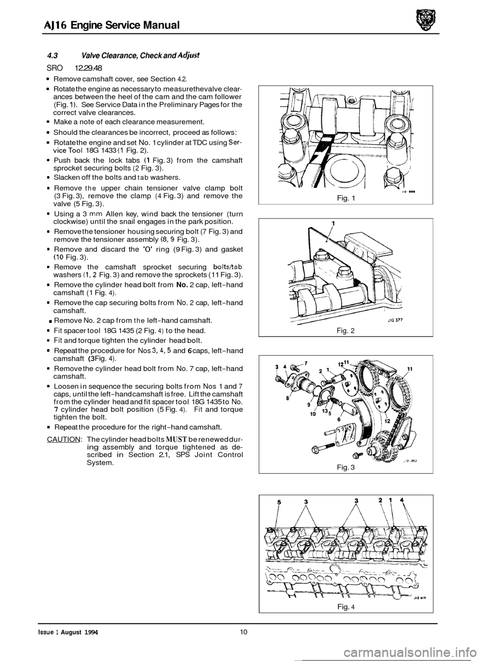
1 Remove camshaft cover, see Section 4.2.
1 Rotate the engine as necessary to measurethevalve clear- ances between the heel of the cam and the cam follower
(Fig.
1). See Service Data in the Preliminary Pages for the
correct valve clearances.
1 Make a note of each clearance measurement.
1 Should the clearances be incorrect, proceed as follows:
1 Rotate the engine and set No. 1 cylinder at TDC using Ser- viceTool 18G 1433 (1 Fig. 2).
Push back the lock tabs (1 Fig. 3) from the camshaft
sprocket securing bolts (2 Fig. 3).
1 Slacken off the bolts and tab washers.
1 Remove the upper chain tensioner valve clamp bolt
(3 Fig. 3), remove the clamp (4 Fig. 3) and remove the
valve (5 Fig. 3).
1 Using a 3 mm Allen key, wind back the tensioner (turn
clockwise) until the snail engages in the park position.
1 Remove the tensioner housing securing bolt (7 Fig. 3) and
remove the tensioner assembly (8,9 Fig. 3).
1 Remove and discard the '0' ring (9 Fig. 3) and gasket (10 Fig. 3).
1 Remove the camshaft sprocket securing bolts/tab washers (1,2 Fig. 3) and remove the sprockets (1 1 Fig. 3).
1 Remove the cylinder head bolt from No. 2 cap, left-hand
camshaft (1 Fig. 4).
1 Remove the cap securing bolts from No. 2 cap, left-hand
cams haft.
. Remove No. 2 cap from the left-hand camshaft.
1 Fit spacer tool 18G 1435 (2 Fig. 4) to the head.
1 Fit and torque tighten the cylinder head bolt.
1 Repeat the procedure for Nos 3,4,5 and 6 caps, left-hand
camshaft
(3 Fig. 4).
1 Remove the cylinder head bolt from No. 7 cap, left-hand
camshaft.
1 Loosen in sequence the securing bolts from Nos 1 and 7 caps, until the left-hand camshaft is free. Lift the camshaft
from the cylinder head and fit spacer tool 18G 1435 to No. 7 cylinder head bolt position (5 Fig. 4). Fit and torque
tighten the bolt.
Valve Clearance, Check and Aa'just
1 Repeat the procedure for the right-hand camshaft.
CAUTION: The cylinder head bolts
MUST be renewed dur- ing assembly and torque tightened as de- scribed in Section 2.1, SPS Joint Control
System.
111 ...
Fig. 1
1
Fig. 2
Fig. 3
Fig. 4
Issue 1 August 1994 10 ~~
Page 30 of 73
1.
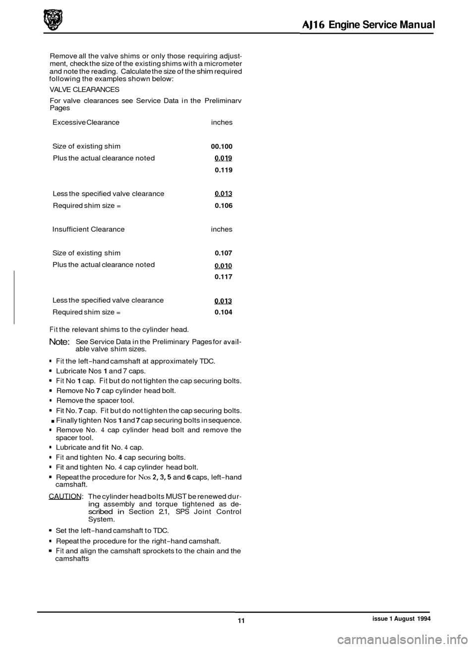
Remove all the valve shims or only those requiring adjust- ment, check the size of the existing shims with a micrometer
and note the reading. Calculate the size of the
shim required
following the examples shown below:
VALVE CLEARANCES
For valve clearances see Service Data in the Preliminarv
I Pages
Excessive Clearance inches
Size of existing shim
Plus the actual clearance noted
Less the specified valve clearance
I
00.100
0.019
0.119
0.013
Required shim size = 0.106
Insufficient Clearance inches
Size of existing shim
0.107
Plus the actual clearance noted o.010
0.117
Less the specified valve clearance 0.013
Required shim size = 0.104
I
Fit the relevant shims to the cylinder head.
Note:
. Fit the left-hand camshaft at approximately TDC.
. Lubricate Nos 1 and 7 caps.
1 Fit No 1 cap. Fit but do not tighten the cap securing bolts.
. Remove No 7 cap cylinder head bolt.
. Remove the spacer tool.
1 Fit No. 7 cap. Fit but do not tighten the cap securing bolts.
. Finally tighten Nos 1 and 7 cap securing bolts in sequence.
. Remove No. 4 cap cylinder head bolt and remove the
. Lubricate and fit No. 4 cap.
. Fit and tighten No. 4 cap securing bolts.
. Fit and tighten No. 4 cap cylinder head bolt.
9 Repeat the procedure for Nos 2,3,5 and 6 caps, left-hand
CAUTION: The cylinder head bolts MUST be renewed dur- ing assembly and torque tightened as de- scribed in Section 2.1, SPS Joint Control
System.
See
Service Data in the Preliminary Pages for
avail- able valve shim sizes.
I
3
spacer tool.
camshaft.
1 Set the left-hand camshaft to TDC.
. Repeat the procedure for the right-hand camshaft.
Fit and align the camshaft sprockets to the chain and the
camshafts
AJ16 Engine Service Manual
11 issue 1 August 1994
Page 31 of 73

AJ16 Engine Service Manual
1 Move all the slack in the chain to the tensioner side.
1 Fit upper chain tensioner tool 18G 14361A (2 Fig. 1). Fit and
tighten the tool securing bolts (1 Fig. 1).
1 Tension the cam chain.
1 Remove the camshaft coupling (12 Fig.2) from the
sprocket (11 Fig. 2) and align the securing bolt holes. Fit
the bolts (2 Fig. 2) and tab washers (1 Fig. 2), tighten the
securing bolts and lock over the tabs.
1 Repeat the procedure for the other sprocket.
1 Slacken off the chain tensioner tool securing bolts
1 Remove the tensioner tool.
1 Clean the tensioner assembly and gasket faces.
= Fit a new housing gasket (10 Fig. 2). Fit and lubricate a
new ‘0’ ring (9 Fig. 2).
1 Fitthetensionerassembly (8,9 Fig. 2)tothecylinderhead.
Fit andtighten thetensioner assembly securing bolt (3 Fig.
2).
(1 Fig. 1).
1 Fit but do not tighten the valve clamp bolt.
1 Clean the valve assembly and fit new ‘0‘ rings (13 Fig. 2).
Lubricate the tensionervalve (5 Fig. 2). Using an Allen key,
release the tensioner, by turning the
Allen key anti-clock- wise.
1 Fit the tensioner valve (5 Fig. 2). Position the clamp (4 Fig. 2) over the valve.
1 Tighten the clamp bolt (3 Fig. 2).
1 Refit the camshaft cover, see Section 4.2. Fig.
1
I Fia. 2
Issue 1 August 1994 12