ESP JAGUAR XJ 1994 2.G AJ16 Engine Manual
[x] Cancel search | Manufacturer: JAGUAR, Model Year: 1994, Model line: XJ, Model: JAGUAR XJ 1994 2.GPages: 73, PDF Size: 2.06 MB
Page 21 of 73
AJ16 Engine Service Manual
1.5 Coohg System
The engine is liquid cooled by a mixture of water and anti-freeze circulating around the coolant passages. The coolant
pump is mounted on the left hand side of the cylinder block and is driven from the crankshaft nose by a three point
belt drive (which includes the generator). The pump is a fully assembled bolt
-on unit. The coolant is fed into the cylin- der block at two places via an external delivery pipe. The coolant is drawn from the cylinder head via a self-contained
thermostat housing back to the radiator or recirculated according to the thermostat position.
7.6 Supercharger
The supercharger optionally available on the 4,O liter engine is a Roots blower type which gives better engine efficiency
at part throttle conditions and responsive off
-boost performance. The principal changes to the engine for the super- charged version are to the piston, valve timing, intake manifold and the additional drive to the supercharger. A lower
compression ratio
of 8.5:l is used which provides the optimum balance between high speed performance and fuel
economy.
The engine heat exchanger of the intercooler system is incorporated into the intake manifold. The blower incorporates
an air by
-pass system which improves efficiency under part throttle conditions. The by-pass valve is controlled by a vacuum actuator referenced to the intake manifold pressure.
2. SERVICE PROCEDURES
2.1 SPS )oint Control System
Afeature of the engine is the use of the SPS joint control system on the cylinder head bolts, crankshaft main bearing
bolts and connecting rod bearing nuts and bolts. This system ensures that the joints receive maximum clamp loading
for a given fixing size and type of material by tightening the fixing to its particular yield point. This greatly helps to
prevent premature cylinder head gasket failures.
0
CAUTION: All SPS fixings must be used only once. Discard
fixings on removal and replace with new bolts/
nuts every time a 'strip down' has been carried
out.
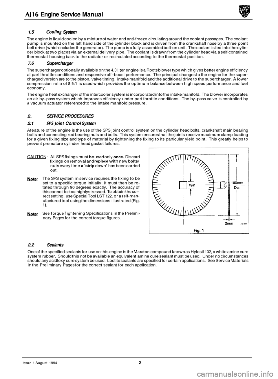
The SPS system in service requires the fixing to be
set to a specific torque initially; it must then be ro
- tated through 90 degrees exactly. The accuracy of
thiscannot betoo highlystressed. Toobtainthecor- rect setting, use Special Tool LST 122, or a self-man-
ufactured tool using the dimensions illustrated (Fig.
I).
SeeTorqueTightening Specifications in the Prelimi-
nary Pages for the correct torque figures.
b:
w:
2.2 Sealants
One of the specified sealants for use on this engine is the Marston compound known as Hylosil 102, a white amine cure
system rubber. Should this not be available an equivalent amine cure sealant must be used. Under no circumstances
should any acidtoxy cure system be used. Loctite sealants are specified for certain applications. See Service Materials
in the Preliminary Pages for the correct sealant for each application.
Issue 1 August 1994 2
Page 40 of 73
AJ16 Engine Service Manual
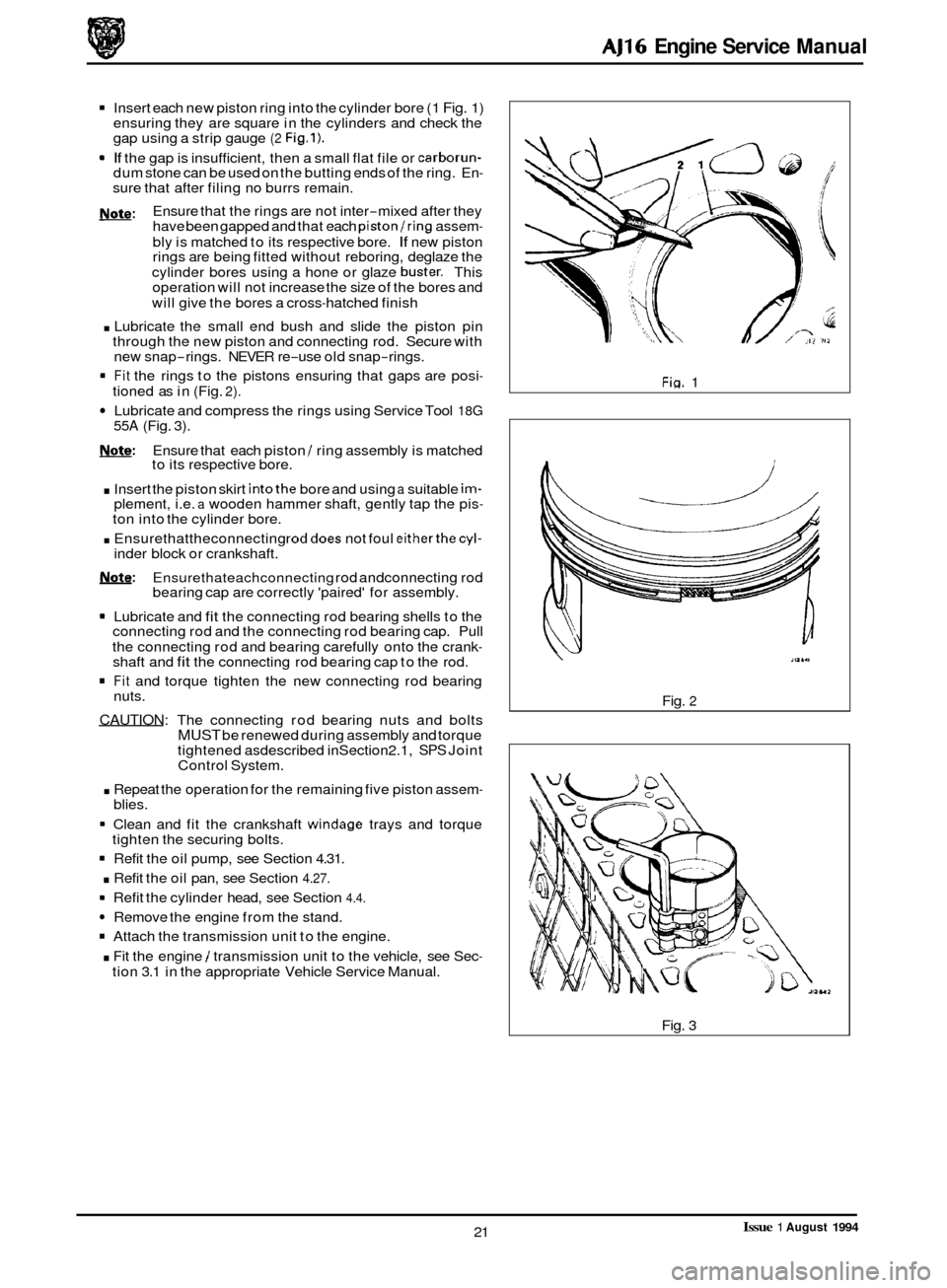
Insert each new piston ring into the cylinder bore (1 Fig. 1)
ensuring they are square in the cylinders and check the
gap using a strip gauge
(2 Fig.1).
9 If the gap is insufficient, then a small flat file or carborun- dum stone can be used on the butting ends of the ring. En- sure that after filing no burrs remain.
Ensure that the rings are not inter
-mixed after they
have been gapped and that each piston/ring assem-
bly is matched to its respective bore. If new piston
rings are being fitted without reboring, deglaze the
cylinder bores using a hone or glaze
buster. This
operation will not increase the size of the bores and
will give the bores a cross
-hatched finish
. Lubricate the small end bush and slide the piston pin
through the new piston and connecting rod. Secure with
new snap
-rings. NEVER re-use old snap-rings.
Fit the rings to the pistons ensuring that gaps are posi- tioned as in (Fig. 2).
Lubricate and compress the rings using Service Tool 18G 55A (Fig. 3).
w:
b: Ensure that each piston / ring assembly is matched
to its respective bore.
. Insert the piston skirt intothe bore and using a suitable im- 0
plement, i.e. a wooden hammer shaft, gently tap the pis- ton into the cylinder bore.
. Ensurethattheconnecting roddoes not foul eitherthecyl- inder block or crankshaft.
Note: Ensurethateachconnecting rod andconnecting rod
m Lubricate and fit the connecting rod bearing shells to the
connecting rod and the connecting rod bearing cap. Pull
the connecting rod and bearing carefully onto the crank
- shaft and fit the connecting rod bearing cap to the rod.
Fit and torque tighten the new connecting rod bearing
nuts.
CAUTION: The connecting rod bearing nuts and bolts MUST be renewed during assembly and torque
tightened asdescribed inSection2.1, SPS Joint
Control System.
. Repeat the operation for the remaining five piston assem-
bearing cap are correctly 'paired' for assembly.
blies.
Clean and fit the crankshaft
windage trays and torque
-
0 - - tighten the securing bolts.
Refit the oil pump, see Section 4.31.
. Refit the oil pan, see Section 4.27.
Refit the cylinder head, see Section 4.4.
Remove the engine from the stand.
Attach the transmission unit to the engine.
. Fit the engine / transmission unit to the vehicle, see Sec- tion 3.1 in the appropriate Vehicle Service Manual.
Fin. 1
itl6.l
Fig. 2
Fig. 3
Issue 1 August 1994 21
Page 42 of 73
AJ16 Engine Service Manual
4.9
SRO 12.21.39
Main Bearing, Engine Set, Renew
Remove components required for access and proceed as fol- lows.
1 Remove the oil pan see, see Section 4.27.
1 Remove the oil pump, see Section 4.31.
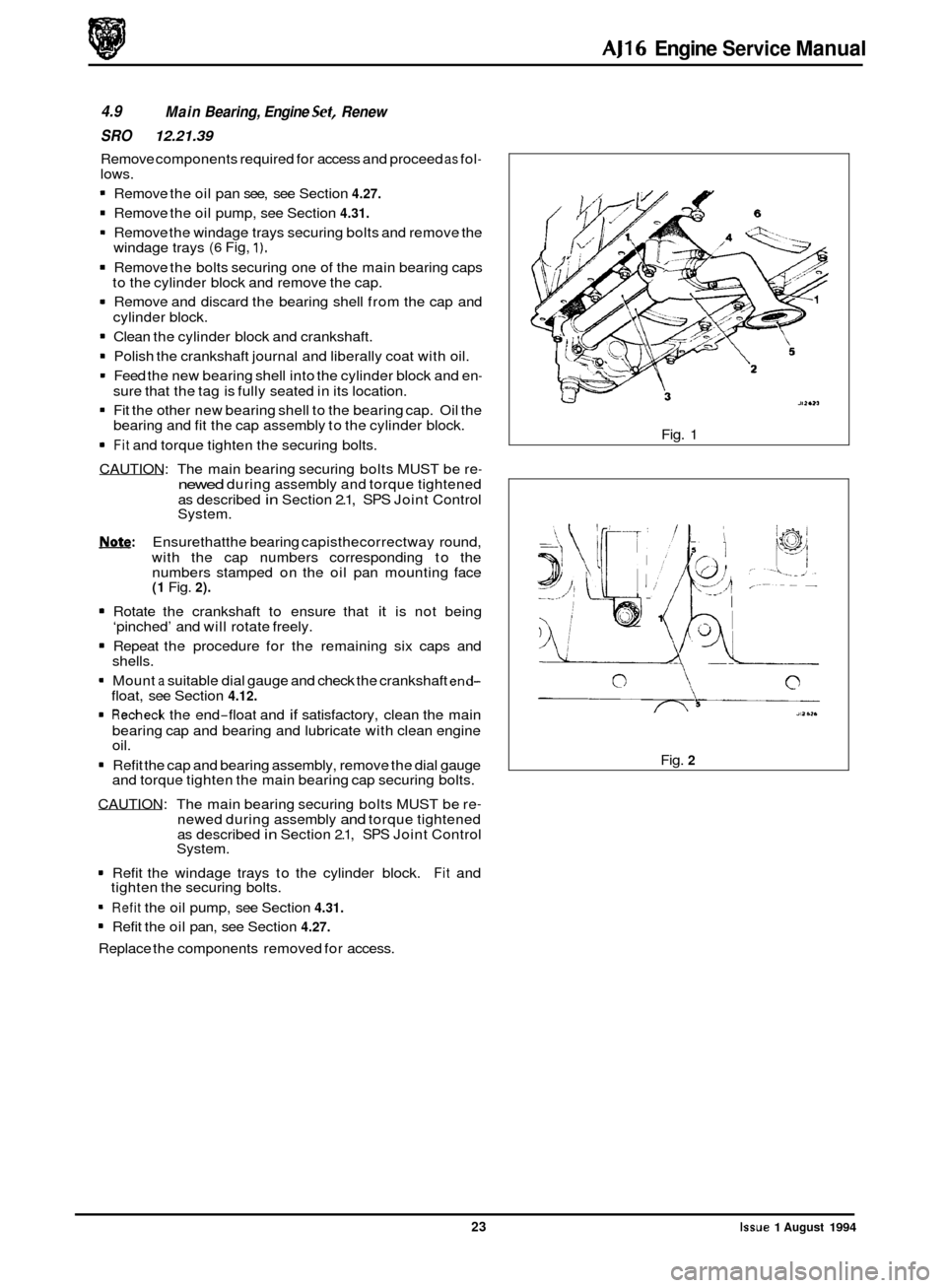
* Remove the windage trays securing bolts and remove the
1 Remove the bolts securing one of the main bearing caps
1 Remove and discard the bearing shell from the cap and
1 Clean the cylinder block and crankshaft.
1 Polish the crankshaft journal and liberally coat with oil.
1 Feed the new bearing shell into the cylinder block and en- sure that the tag is fully seated in its location.
1 Fit the other new bearing shell to the bearing cap. Oil the
bearing and fit the cap assembly to the cylinder block.
1 Fit and torque tighten the securing bolts.
CAUTION: The main bearing securing bolts MUST be re
- newed during assembly and torque tightened
as described
in Section 2.1, SPS Joint Control
System.
Note: Ensurethatthe bearing capisthecorrectway round,
with the cap numbers corresponding to the
numbers stamped on the oil pan mounting face
(1 Fig. 2).
1 Rotate the crankshaft to ensure that it is not being
‘pinched’ and will rotate freely.
1 Repeat the procedure for the remaining six caps and
shells.
1 Mount a suitable dial gauge and check the crankshaft end- float, see Section 4.12.
1 Recheck the end-float and if satisfactory, clean the main
bearing cap and bearing and lubricate with clean engine
oil.
1 Refit the cap and bearing assembly, remove the dial gauge
and torque tighten the main bearing cap securing bolts.
CAUTION: The main bearing securing bolts MUST be re
- newed during assembly and torque tightened
as described in Section 2.1, SPS Joint Control
System.
1 Refit the windage trays to the cylinder block. Fit and
1 Refit the oil pump, see Section 4.31.
1 Refit the oil pan, see Section 4.27.
Replace the components removed for access.
windage trays
(6 Fig, 1).
to
the cylinder block and remove the cap.
cylinder block.
0
tighten the securing bolts. Fig.
1
Fig. 2
23
Issue 1 August 1994
Page 46 of 73
AJ16 Engine Service Manual
4.12
SRO 12.21.26
Crankshaft End-float, Check and A4ust
Remove components as required for access and proceed as
follows.
Remove the oil pan, see Section 4.27.
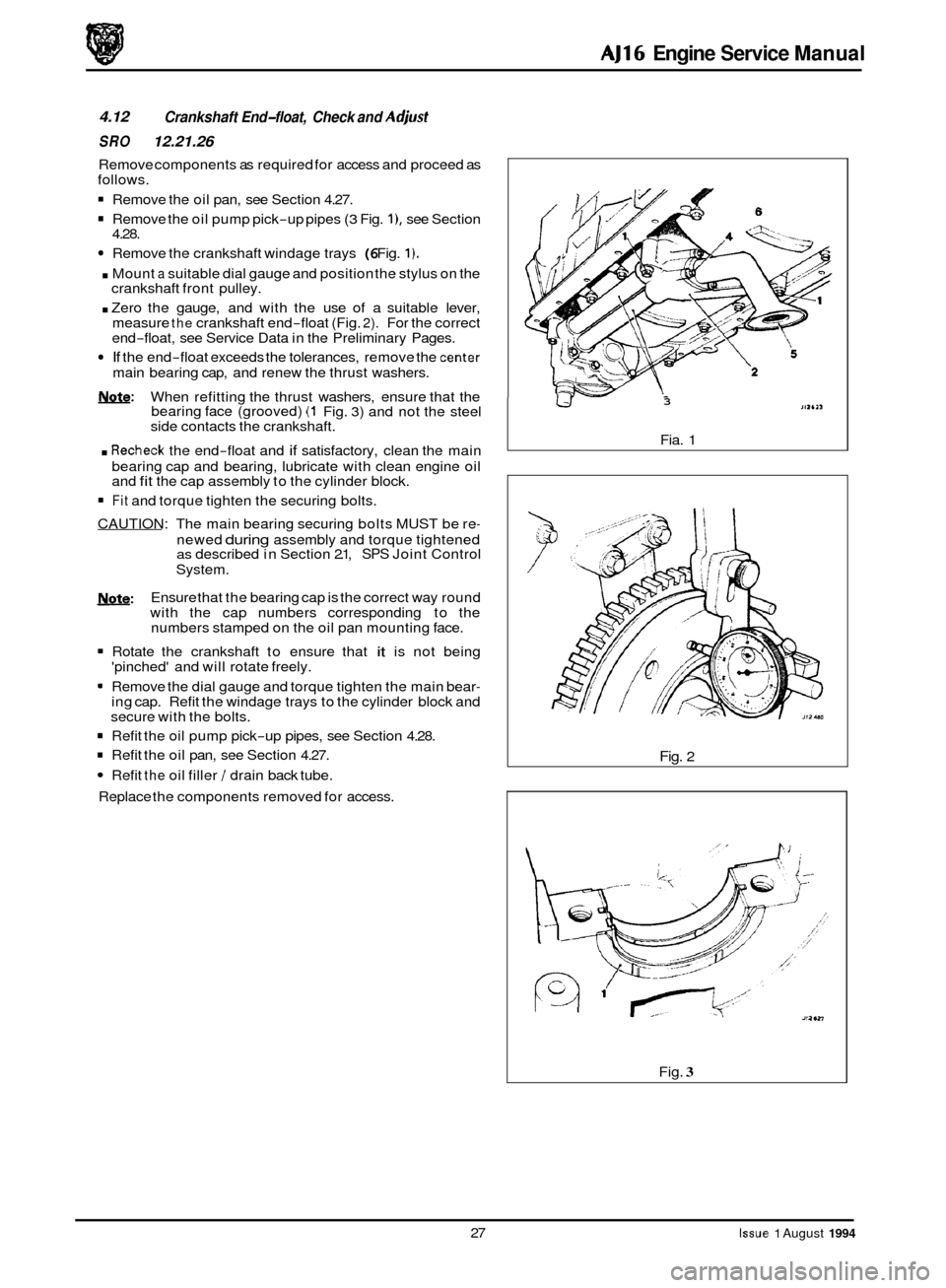
Remove the oil pump pick-up pipes (3 Fig. I), see Section
Remove the crankshaft windage trays (6 Fig. 1).
. Mount a suitable dial gauge and position the stylus on the
crankshaft front pulley.
. Zero the gauge, and with the use of a suitable lever,
measure the crankshaft end-float (Fig. 2). For the correct
end-float, see Service Data in the Preliminary Pages.
If the end-float exceeds the tolerances, remove the center
main bearing cap, and renew the thrust washers.
&&: When refitting the thrust washers, ensure that the
bearing face (grooved) (1 Fig. 3) and not the steel
side contacts the crankshaft.
. Recheck the end-float and if satisfactory, clean the main
bearing cap and bearing, lubricate with clean engine oil
and
fit the cap assembly to the cylinder block.
4.28. 0
Fit and
torque tighten the securing bolts.
CAUTION: The main bearing securing bolts MUST be re
-
newed during assembly and torque tightened as described in Section 2.1, SPS Joint Control
System.
Ensure that the bearing cap is the correct way round
with the cap numbers corresponding to the
numbers stamped on the oil pan mounting face.
Rotate the crankshaft to ensure that it is not being
'pinched' and will rotate freely.
m Remove the dial gauge and torque tighten the main bear- ing cap. Refit the windage trays to the cylinder block and
secure with the bolts.
w:
Refit the oil pump pick-up pipes, see Section 4.28.
Refit the oil pan, see Section 4.27.
Refit the oil filler / drain back tube.
Replace the components removed for access.
0
3
Fia. 1
Fig. 2
Fig.
3
27 Issue 1 August 1994
Page 54 of 73
AJ16 Engine Service Manual
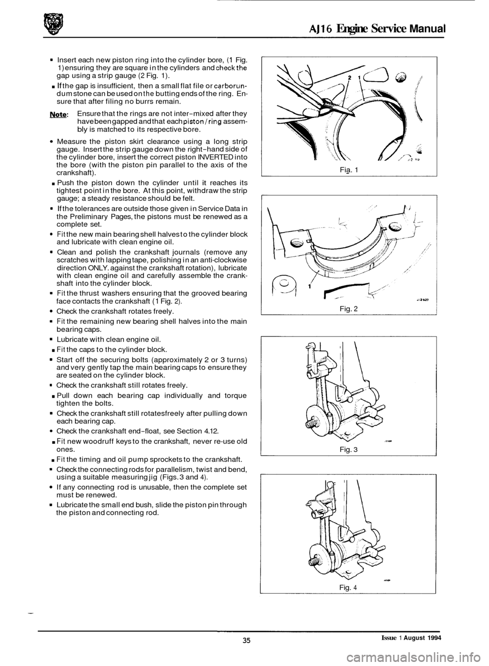
0 1 Insert each new piston ring into the cylinder bore, (1 Fig. 1) ensuring they are square in the cylinders and checkthe gap using a strip gauge (2 Fig. 1).
. If the gap is insufficient, then a small flat file or carborun- dum stone can be used on the butting ends of the ring. En- sure that after filing no burrs remain.
Ensure that the rings are not inter
-mixed after they
have been gapped and that each piston/ring assem- bly is matched to its respective bore.
Measure the piston skirt clearance using a long strip
gauge. Insert the strip gauge down the right-hand side of
the cylinder bore, insert the correct piston INVERTED into
the bore (with the piston pin parallel to the axis of the
crankshaft).
. Push the piston down the cylinder until it reaches its
tightest point in the bore. At this point, withdraw the strip
gauge; a steady resistance should be felt.
1 If the tolerances are outside those given in Service Data in
the Preliminary Pages, the pistons must be renewed as a
complete set.
Note:
0
Fit the new main bearing shell halves to the cylinder block
and lubricate with clean engine oil.
1 Clean and polish the crankshaft journals (remove any
scratches with lapping tape, polishing in an anti-clockwise
direction ONLY. against the crankshaft rotation), lubricate
with clean engine oil and carefully assemble the crank
- shaft into the cylinder block.
1 Fit the thrust washers ensuring that the grooved bearing
Check the crankshaft rotates freely.
1 Fit the remaining new bearing shell halves into the main
1 Lubricate with clean engine oil.
. Fit the caps to the cylinder block.
1 Start off the securing bolts (approximately 2 or 3 turns)
and very gently tap the main bearing caps to ensure they
are seated on the cylinder block.
face contacts
the crankshaft
(1 Fig. 2).
bearing caps.
= Check the crankshaft still rotates freely.
. Pull down each bearing cap individually and torque
1 Check the crankshaft still rotatesfreely after pulling down
tighten
the bolts.
each bearing cap.
Check the crankshaft end-float, see Section 4.12.
. Fit new woodruff keys to the crankshaft, never re-use old
. Fit the timing and oil pump sprockets to the crankshaft.
1 Check the connecting rods for parallelism, twist and bend,
If any connecting rod is unusable, then the complete set
1 Lubricate the small end bush, slide the piston pin through
ones.
using
a suitable measuring jig (Figs.
3 and 4).
must be renewed.
the piston and connecting rod. Fia.
1
Fig. 2
Fig. 3
Fig. 4
Issue 1 August 1994 35