engine coolant JAGUAR XJ 1994 2.G AJ16 Engine Manual
[x] Cancel search | Manufacturer: JAGUAR, Model Year: 1994, Model line: XJ, Model: JAGUAR XJ 1994 2.GPages: 73, PDF Size: 2.06 MB
Page 21 of 73

AJ16 Engine Service Manual
1.5 Coohg System
The engine is liquid cooled by a mixture of water and anti-freeze circulating around the coolant passages. The coolant
pump is mounted on the left hand side of the cylinder block and is driven from the crankshaft nose by a three point
belt drive (which includes the generator). The pump is a fully assembled bolt
-on unit. The coolant is fed into the cylin- der block at two places via an external delivery pipe. The coolant is drawn from the cylinder head via a self-contained
thermostat housing back to the radiator or recirculated according to the thermostat position.
7.6 Supercharger
The supercharger optionally available on the 4,O liter engine is a Roots blower type which gives better engine efficiency
at part throttle conditions and responsive off
-boost performance. The principal changes to the engine for the super- charged version are to the piston, valve timing, intake manifold and the additional drive to the supercharger. A lower
compression ratio
of 8.5:l is used which provides the optimum balance between high speed performance and fuel
economy.
The engine heat exchanger of the intercooler system is incorporated into the intake manifold. The blower incorporates
an air by
-pass system which improves efficiency under part throttle conditions. The by-pass valve is controlled by a vacuum actuator referenced to the intake manifold pressure.
2. SERVICE PROCEDURES
2.1 SPS )oint Control System
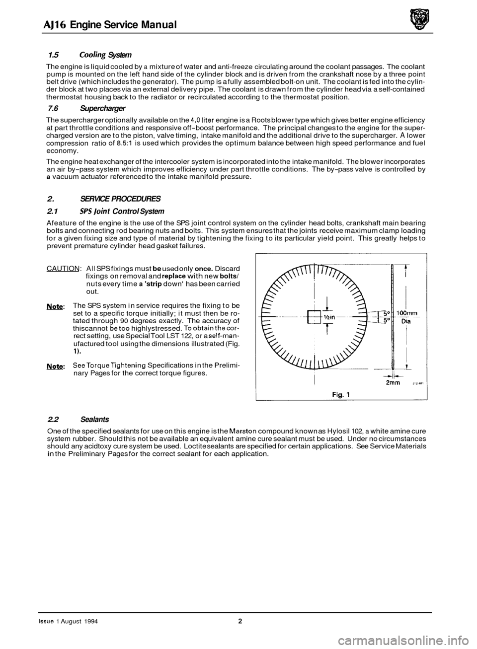
Afeature of the engine is the use of the SPS joint control system on the cylinder head bolts, crankshaft main bearing
bolts and connecting rod bearing nuts and bolts. This system ensures that the joints receive maximum clamp loading
for a given fixing size and type of material by tightening the fixing to its particular yield point. This greatly helps to
prevent premature cylinder head gasket failures.
0
CAUTION: All SPS fixings must be used only once. Discard
fixings on removal and replace with new bolts/
nuts every time a 'strip down' has been carried
out.
The SPS system in service requires the fixing to be
set to a specific torque initially; it must then be ro
- tated through 90 degrees exactly. The accuracy of
thiscannot betoo highlystressed. Toobtainthecor- rect setting, use Special Tool LST 122, or a self-man-
ufactured tool using the dimensions illustrated (Fig.
I).
SeeTorqueTightening Specifications in the Prelimi-
nary Pages for the correct torque figures.
b:
w:
2.2 Sealants
One of the specified sealants for use on this engine is the Marston compound known as Hylosil 102, a white amine cure
system rubber. Should this not be available an equivalent amine cure sealant must be used. Under no circumstances
should any acidtoxy cure system be used. Loctite sealants are specified for certain applications. See Service Materials
in the Preliminary Pages for the correct sealant for each application.
Issue 1 August 1994 2
Page 22 of 73

AJ16 Engine Service Manual
FAULT DIAGNOSIS
3.1 Introduction
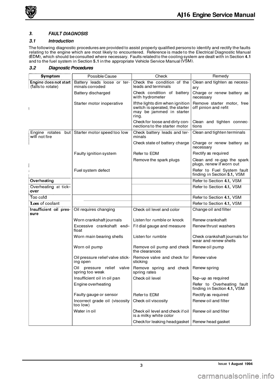
The following diagnostic procedures are provided to assist properly qualified persons to identify and rectify the faults
relating to the engine which are most likely to encountered. Reference is made to the Electrical Diagnostic Manual
(EDM), which should be consulted where necessary. Faults related to the cooling system are dealt with in Section 4.1
and to the fuel system in Section 5.1 in the appropriate Vehicle Service Manual (VSM).
3.2 Diagnostic Procedures
(fails to rotate)
I Engine rotates but 0 I will not fire
I
i
/Overheating
Overheating at tick-
Too cold
Loss of coolant Possible
Cause
Battery leads loose or ter
- minals corroded
Battery discharged
Starter motor inoperative
Starter motor speed too
low
Faulty ignition system
Fuel system defect
Oil requires changing
Worn crankshaft journals
Excessive crankshaft
end- float
Worn main bearing shells
Worn oil pump Oil pressure relief valve stick
- ing open
Oil pressure relief valve
spring too weak
Insufficient oil in oil pan
Engine overheating
Faulty gauge or sensor
Incorrect grade oil (viscosity
too low)
Water in oil Check
Check the condition of the
leads and terminals
Check condition of battery
with hydrometer
If the lights dim when ignition
switch is operated, the starter
may be jammed in starter
ring.
Check for loose and dirty con
- nections to the starter motor
Check battery leads and ter
- minals
Check state of battery charge
Refer to EDM
Remove the spark plugs
Check oil level and color
Listen for rumble or knock
Fit dial gauge and measure
Listen for rumble
Remove oil pump and check
the clearances
Remove valve and check for
sticking
Remove spring and check
spring rates
Check oil level
Refer to EDM
Check oil viscosity
Checkoil level and check if oil
is a milky white color
Check for leaking head gasket Remedy
Clean and tighten as necess
-
ary
Charge or renew battery as
necessary
Remove starter motor, free
off pinion and refit
Clean and tighten connec
- tions
Clean and tighten terminals
Charge or renew battery
as necessary
Rectify as required
Clean and re
-gap the spark
plugs, renew if worn out
Refer to Fuel System fault
finding in Section
5.1, VSM
Refer to Section
4.1, VSM
Refer to Section
4.1, VSM
Refer to Section
4.1, VSM
Refer to Section
4.1, VSM
Change oil and filter
Renew crankshaft
Renew thrust washers
Check crankshaft journals for
wear and renew shells
Renew oil pump
Renew valve
Renew spring
lop-up as required
Refer to Overheating fault
finding in Section
4.1, VSM
Rectify as required
Renew oil and filter
Renew oil and filter
Renew head gasket
Issue 1 August 1994 3
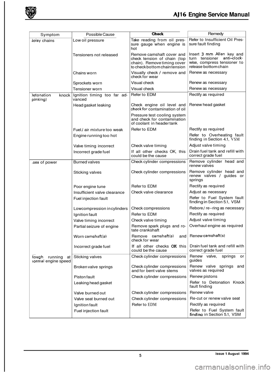
Page 24 of 73

AJ16 Engine Service Manual
Symptom
Joisy chains
)etonation knock pinking)
.oss of power
Gugh running at iormal engine speed Possible
Cause
Low oil pressure
Tensioners not released
Chains worn
Sprockets worn
Tensioner worn
Ignition timing too far ad
- vanced
Head gasket leaking
Fuel
/ air mixture too weak
Engine running
too hot
Valve timing incorrect
Incorrect grade fuel
Burned valves Sticking valves
Poor engine tune
Insufficient valve clearance
Fuel injection fault
Lowcompression in cylinders
Ignition fault
Valve timing incorrect
Partial seizure of engine
Worn
camshaftb)
Incorrect grade fuel
Sticking valves Broken valve springs Piston fault
Leaking head gasket
Valve burned out
Valve seat burned out
Ignition fault
Fuel injection fault
Check
Take reading from oil pres- sure gauge when engine is
hot
Remove camshaft cover and
check tension of chain (top
chain). Remove timing cover
to check bottom chain tension
Visually check
/ remove and
check for wear
Visual check
Visual check
Refer to EDM
Check engine oil level and
checkfor contamination of oil
Pressure test cooling system
and check for contamination
of coolant in header tank
Refer to EDM
Check valve timing
If all other checks
OK, this
could be the cause
Check cylinder compressions
Check cylinder compressions
Refer to EDM
Check valve clearance
Check compressions
Refer to EDM
Check valve timing
Remove spark plugs and ro
- tate crankshaft
Remove
camshaft(s) and
check for wear
If all other checks OK this
could be the cause
Check cylinder compressions
Check cylinder compressions
and for bent valve stems
Check cylinder cornpressions
Check cylinder compressions
Check cylinder compressions
Refer to
EDM
Remedy
Refer to Insufficient Oil Pres- sure fault finding
Insert
3 mm Allen key and
turn tensioner anti-clock- wise, compress tensioner to
release bottom chain
Renew as necessary
Renew as necessary
Renew as necessary
Rectify as required
Renew head gasket
Rectify
as required
Refer
to Overheating fault
finding in Section 4.1, VSM
Adjust valve timing
Drain fuel tank and refill with
correct grade fuel
Remove cylinder head and
renew valves
Remove cylinder head and
renew valves
/ guides or
springs
Rectify as required
Adjust as necessary
Refer to Fuel System fault
finding in Section 5.1, VSM
Rebore
1 re-ring as necessary
Rectify as required
Adjust valve timing
Overhaul engine as required
Renew
camshaft(s)
Drain fuel tank and refill with
correct grade fuel
Renew valve, springs or
guides
Renew valve springs and
valves as required
Renew pistons
Refer to Detonation Knock
fault finding
Renew valve
Re
-cut or renew valve seat
Rectify as required
Refer to Fuel System fault
Tindim in Section 5.1, VSM
issue 1 August 1994 5
Page 52 of 73

AJ16 Engine Service Manual
4.18 &;ne Assembly, Overhaul
SRO 12.41.05
. Remove the engine and transmission unit, see Section 3.1
. Remove the transmission unit from the engine.
. Fit the engine to a stand.
. Place a drain tray belowthe cylinder block drain plug and
Overhaul the cylinder head, see Section 4.5.
1 Remove the oil pan, see Section 4.27.
. Remove the oil pump, see Section 4.31.
. Remove the windage trays.
. Clean all components, check for damage and wear and
. Remove the rear oil seal housing, see Section 4.1 4.
. Remove the timing cover assembly.
1 Remove the pedestal bolts and tab washer.
. Remove the pedestal / tensioner assembly and damper.
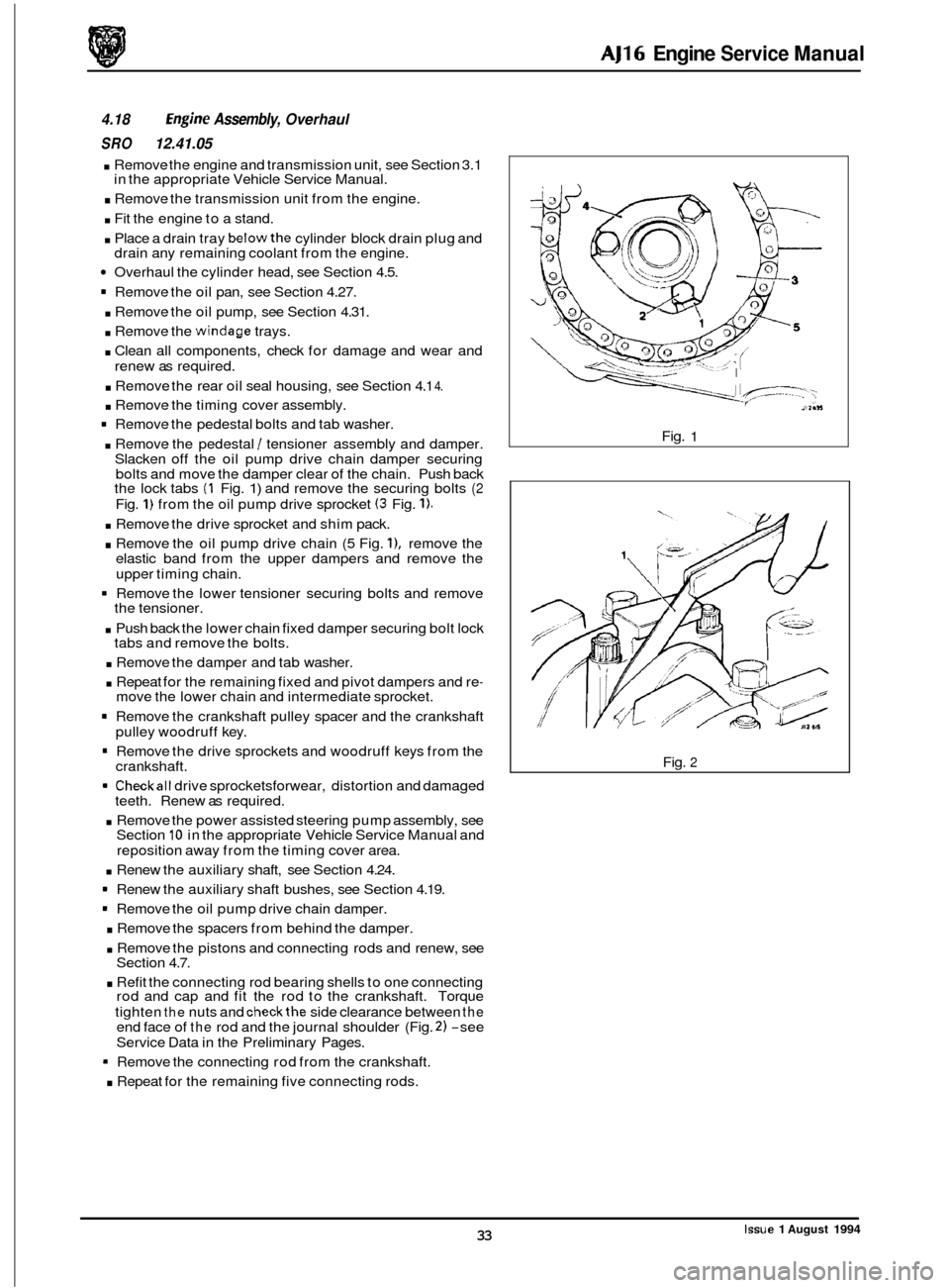
Slacken off the oil pump drive chain damper securing
bolts and move the damper clear of the chain. Push back
the lock tabs
(1 Fig. 1) and remove the securing bolts (2
Fig. 1) from the oil pump drive sprocket (3 Fig. 1).
in the appropriate Vehicle Service Manual.
drain any remaining coolant from the engine.
renew as required.
. Remove the drive sprocket and shim pack.
. Remove the oil pump drive chain (5 Fig. l), remove the
elastic band from the upper dampers and remove the
upper timing chain.
1 Remove the lower tensioner securing bolts and remove
the tensioner.
. Push back the lower chain fixed damper securing bolt lock
tabs and remove the bolts.
. Remove the damper and tab washer.
. Repeat for the remaining fixed and pivot dampers and re- move the lower chain and intermediate sprocket.
Remove the crankshaft pulley spacer and the crankshaft
pulley woodruff key.
= Remove the drive sprockets and woodruff keys from the
crankshaft.
1 Checkall drive sprocketsforwear, distortion and damaged
teeth. Renew as required.
. Remove the power assisted steering pump assembly, see
Section 10 in the appropriate Vehicle Service Manual and
reposition away from the timing cover area.
. Renew the auxiliary shaft, see Section 4.24.
1 Renew the auxiliary shaft bushes, see Section 4.19.
1 Remove the oil pump drive chain damper.
. Remove the spacers from behind the damper.
. Remove the pistons and connecting rods and renew, see
Section 4.7.
. Refit the connecting rod bearing shells to one connecting
rod and cap and fit the rod to the crankshaft. Torque
tighten
the nuts and checkthe side clearance between the end face of the rod and the journal shoulder (Fig. 2) -see
Service Data in the Preliminary Pages.
Remove the connecting rod from the crankshaft.
. Repeat for the remaining five connecting rods. Fig.
1
Fig. 2
Issue 1 August 1994 33