manual transmission JAGUAR XJ 1994 2.G ZF Automatic Transmission Manual
[x] Cancel search | Manufacturer: JAGUAR, Model Year: 1994, Model line: XJ, Model: JAGUAR XJ 1994 2.GPages: 74, PDF Size: 2.66 MB
Page 33 of 74

ZF Automatic Transmissions Service Manual
63
Q
I IIIU
m
Issue 1 August 1994 28
Page 34 of 74

ZF Automatic Transmissions Service Manual
9' 9 8'
F
I
Issue 1 August 1994
Page 35 of 74

ZF Automatic Transmissions Service Manual
r--
Q
I
30 Issue 1 August 1994
Page 36 of 74

ZF Automatic Transmissions Service Manual
Rs
v--
U
Issue 1 August 1994 31
Page 37 of 74

ZF Automatic Transmissions Service Manual
-a -c -2 -a
I
Issue 1 August 1994 32
Page 38 of 74

ZF Automatic Transmissions Service Manual
1.3 FAULT DIAGNOSIS
The followina tables are intended as a auide to diaanosis of Dossible faults in the ZF 4 HP 22 transmission. When the
fault involvesa leak, it is recommendedthat it is located by the use of a crack detection fluid, eg Met-L-Check, which
is available in spray form and permits the leak to be located after a short test drive.
1.3.1 Initial Checks
Note: Before attempting diagnosis, ensure that the following settings are checked:
Transmission oil level.
. Ensure that the transmission is at normal operating temperature, eg by conducting a road test. If starting from cold,
. Check that the vehicle is on level ground.
. Firmly apply the parking and footbrakes and run the engine at idle speed.
. To ensure that the system is primed, slowly move the selector lever through all the gear positions.
. With the engine still running, engage ‘P‘ Park, withdraw the dipstick and wipe with a lint free cloth.
. Replace the dipstick slowly and withdraw it noting the level.
. Top up as required and recheck the level.
check
for presence of oil on dipstick at idle
in Park before start of road test.
1.3.2 Engine Tune
Selector cable adjustment.
Check gear selection in all selector positions.
If in doubt, select ’N’, disconnect the cable at the gearbox selector lever, check that the gearbox lever is in ’N’ position
. Adjust as necessary, see Vehicle Service Manual.
(third
detent from the rear) and refit the selector cable ball pin to the lever.
Kickdown switch adjustment, see Vehicle Service Manual.
1.3.3 Stall Test
. Ensure the transmission is at normal running temperature.
. Fully apply the parking brake.
. Fully depress the footbrake.
= Select position ‘D‘- Drive.
. Fully depress the accelerator(’kick-down’ detent fully depressed).
. Note the tachometer reading.
Start
the engine.
. Compare the tachometer reading to the specification.
CAUTION: This test must not last more than 5 seconds. Always allow the engine to idle for at least 2 minutes be- tween tests to allow the transmission fluid to cool down. Do not carry out more than three tests in any
half-hour.
1.3.4 Road Test
Fully check all shift speeds and note. Compare the results with the specification in addition to general observations
of transmission behaviour, noises, leaks etc., and consult the following Fault Finding Chart.
CAUTION: When renewing the transmission, ALWAYS flush out the oil cooler and feed and return pipes.
1.3.5 Electrical Checks
If any electrical component fault issuspected, referto the Electrical Diagnostic Manual (EDM) to verify the failure mode
before a repair or replacement is attempted.
Issue 1 August 1994 33
Page 39 of 74
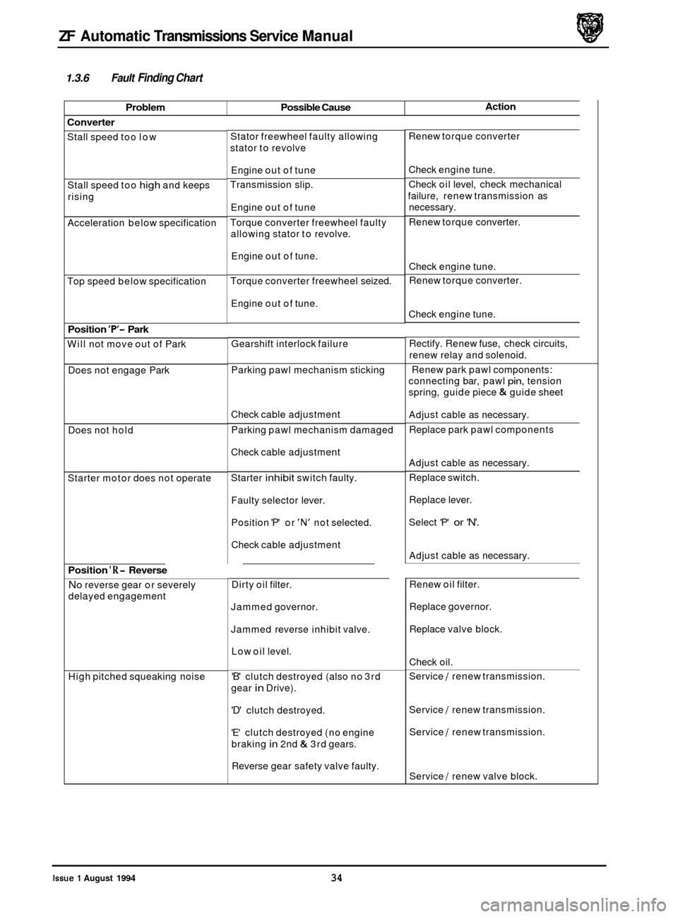
ZF Automatic Transmissions Service Manual
Problem Possible Cause
1.3.6 Fault Finding Chart
Action
Converter
Stall speed too low
Stall speed too
high and keeps
rising
Acceleration below specification
Top speed below specification
Position 'P'- Park
Will not move out of Park
Does not engage Park
Does not hold
Starter motor does not operate
Position 'R- Reverse
No reverse gear or severely
delayed engagement
High pitched squeaking noise Stator freewheel
faulty allowing
stator to revolve
Engine out of tune
Transmission slip.
Engine out of tune
Torque converter freewheel faulty
allowing stator to revolve.
Engine out of tune.
Torque converter freewheel seized.
Engine out of tune.
Gearshift interlock failure
Parking pawl mechanism sticking
Check cable adjustment
Parking pawl mechanism damaged
Check cable adjustment
Starter
inhibit switch faulty.
Faulty selector lever.
Position
'P' or 'N' not selected.
Check cable adjustment
Dirty oil filter.
Jammed governor.
Jammed reverse inhibit valve.
Low oil level.
'B' clutch destroyed (also no 3rd
gear
in Drive).
'D' clutch destroyed.
'E' clutch destroyed (no engine
braking
in 2nd & 3rd gears.
Reverse gear safety valve faulty. Renew
torque converter
Check engine tune.
Check oil level, check mechanical
failure, renew transmission as
necessary.
Renew torque converter.
Check engine tune.
Renew torque converter.
Check engine tune.
Rectify. Renew fuse, check circuits,
renew relay and solenoid.
Renew park pawl components:
connecting bar, pawl
pin, tension
spring, guide piece
& guide sheet
Adjust cable as necessary.
Replace park pawl components
Adjust cable as necessary.
Replace switch.
Replace lever.
Select 'P'
or 'N'.
Adjust cable as necessary.
Renew oil filter.
Replace governor.
Replace valve block.
Check oil.
Service
/ renew transmission.
Service
/ renew transmission.
Service
/ renew transmission.
Service
/ renew valve block.
Issue 1 August 1994 34
Page 41 of 74

ZF Automatic Transmissions Service Manual
Problem Possible Cause
1.3.6 Fault Finding Chart (continued)
Action
No changes at light throttle
setting
Change points incorrect at full
throttle setting
No changes at 'kick-down' - 1st
to 2nd 12nd to 1st
No changes at 'kick-down' - 2nd
to 3rd
13rd to 2nd Dirty
governor.
Shift valves sticking.
'Kick
-down' cable setting incorrect
'Kick
-down' cable setting incorrect
'Kick
-down' cable setting incorrect Renew
governor.
Service
1 renew valve block.
Adjust setting
Adjust setting
Adjust setting
Service
1 renew valve block.
Service
1 renew valve block.
Poor changes
Harsh changes at low throttle Throttle
valve ('kickdown') cable
, setting incorrect
I Defective damper.
Modulation pressure too high.
'Kick
-down' cable setting incorrect. I
j Clutch plates damaged.
!
Soft changes at full throttle and
'kick
-down' Defective damper.
'Kick-down' cable setting incorrect.
I
Adjust setting
Service
/ renew valve block.
Service
1 renew valve block.
Adjust setting
,
Service / renew transmission.
Service
/ renew valve block.
Adjust setting.
Adjust setting.
Harsh changes
at full throttle and
'kick
-down' Modulation
pressure too low.
Clutch plates damaged.
Incorrect modulation pressure.
'Kick
-down' cable setting incorrect.
Defective damper.
Manual change 3rd to 2nd faulty
No engine braking
36 Issue 1 August 1994
Locking valve '2' sticking. Service 1 renew valve
block I governor.
Service
/ renew valve block / governor.
Service
1 renew transmission
Governor faulty.
Brake 'C' or 'E' damaged
Page 42 of 74
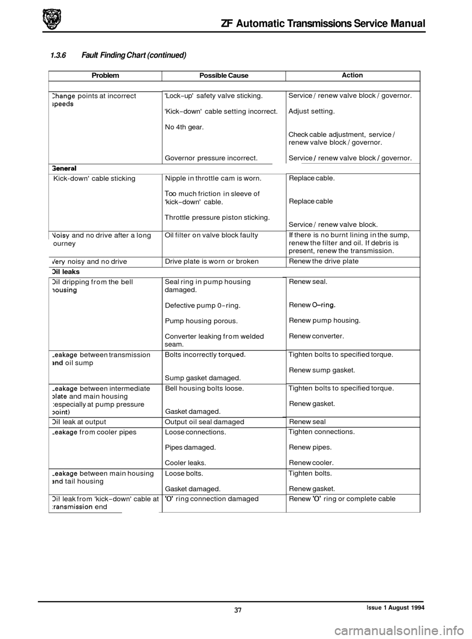
ZF Automatic Transmissions Service Manual
Problem Possible Cause
1.3.6 Fault Finding Chart (continued)
Action
>hange points at incorrect
;peeds
3eneral
Kick-down' cable sticking
Voisy and no drive after a long
ourney
dery noisy and no drive
3il leaks
3il dripping from the bell
iousing
-eakage between transmission
and oil sump
-eakage between intermediate
date and main housing
:especially at pump pressure
Doint)
3il leak at output
-eakage from cooler pipes
-eakage between main housing
jnd tail housing
3il leak from 'kick-down' cable at
:ransmission end 'Lock
-up'
safety valve sticking.
'Kick
-down' cable setting incorrect.
No 4th gear.
Governor pressure incorrect.
Nipple in throttle cam is worn.
Too much friction in sleeve of
'kick
-down' cable.
Throttle pressure piston sticking.
Oil filter on valve block faulty
Drive plate is worn or broken
Seal ring in pump housing
damaged.
Defective pump 0
-ring.
Pump housing porous.
Converter leaking from welded
seam.
Bolts incorrectly
torqued.
Sump gasket damaged.
Bell housing bolts loose.
Gasket damaged.
Output oil seal damaged
Loose connections.
Pipes damaged.
Cooler leaks.
Loose bolts.
Gasket damaged.
'0' ring connection damaged Service
/ renew valve
block / governor.
Adjust setting.
Check cable adjustment, service
/
renew valve block / governor.
Service
1 renew valve block I governor.
Replace cable.
Replace cable
Service
/ renew valve block.
If there is no burnt lining in the sump,
renew the filter and oil. If debris is
present, renew the transmission.
Renew the drive plate
Renew seal.
Renew
@ring.
Renew pump housing.
Renew converter.
Tighten bolts to specified torque.
Renew sump gasket.
Tighten bolts to specified torque.
Renew gasket.
Renew seal
Tighten connections.
Renew pipes.
Renew cooler.
Tighten bolts.
Renew gasket.
Renew
'0' ring or complete cable
issue 1 August 1994 37
Page 44 of 74
ZF Automatic Transmissions Service Manual
2.1
electronic-hydraulic transmission control unit.
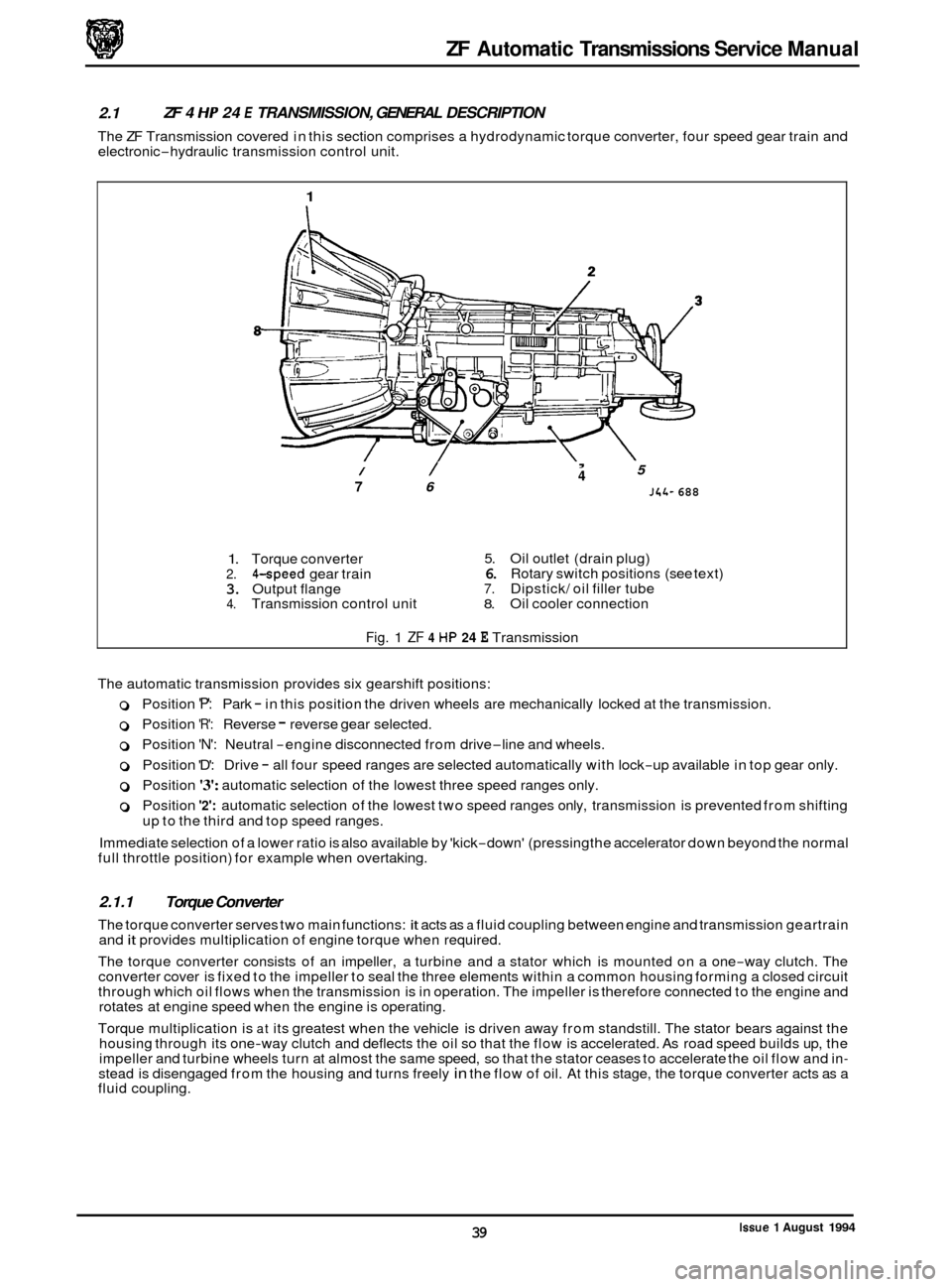
ZF 4 HP 24 E TRANSMISSION, GENERAL DESCRIPTION
The ZF Transmission covered in this section comprises a hydrodynamic torque converter, four speed gear train and
1
/ /
7 6
, 5 4
J4L- 688
1. Torque converter 5. Oil outlet (drain plug)
2. 4-speed gear train 6. Rotary switch positions (see text)
3. Output flange 7. Dipstick/ oil filler tube 4. Transmission control unit 8. Oil cooler connection
Fig. 1 ZF 4 HP 24 E Transmission
The automatic transmission provides six gearshift positions:
0 Position 'P': Park - in this position the driven wheels are mechanically locked at the transmission.
0 Position 'R': Reverse - reverse gear selected.
0 Position 'N': Neutral -engine disconnected from drive-line and wheels.
0 Position 'D': Drive - all four speed ranges are selected automatically with lock-up available in top gear only.
0 Position '3': automatic selection of the lowest three speed ranges only.
0 Position '2': automatic selection of the lowest two speed ranges only, transmission is prevented from shifting
up to the third and top speed ranges.
Immediate selection of a lower ratio is also available by 'kick
-down' (pressing the accelerator down beyond the normal
full throttle position) for example when overtaking.
2.1.1 Torque Converter
The torque converter serves two main functions: it acts as a fluid coupling between engine and transmission geartrain
and it provides multiplication of engine torque when required.
The torque converter consists of an impeller, a turbine and a stator which is mounted on a one
-way clutch. The
converter cover is fixed to the impeller to seal the three elements within a common housing forming a closed circuit
through which oil flows when the transmission is in operation. The impeller is therefore connected to the engine and
rotates at engine speed when the engine is operating.
Torque multiplication is
at its greatest when the vehicle is driven away from standstill. The stator bears against the
housing through its one-way clutch and deflects the oil so that the flow is accelerated. As road speed builds up, the
impeller and turbine wheels turn at almost the same speed, so that the stator ceases to accelerate the oil flow and in- stead is disengaged from the housing and turns freely in the flow of oil. At this stage, the torque converter acts as a
fluid coupling.
Issue 1 August 1994 39