sensor JAGUAR XJ 1994 2.G ZF Automatic Transmission Manual
[x] Cancel search | Manufacturer: JAGUAR, Model Year: 1994, Model line: XJ, Model: JAGUAR XJ 1994 2.GPages: 74, PDF Size: 2.66 MB
Page 5 of 74
ZF Automatic Transmissions Service Manual
Item Description I
IC! Service Data (continued)
Data
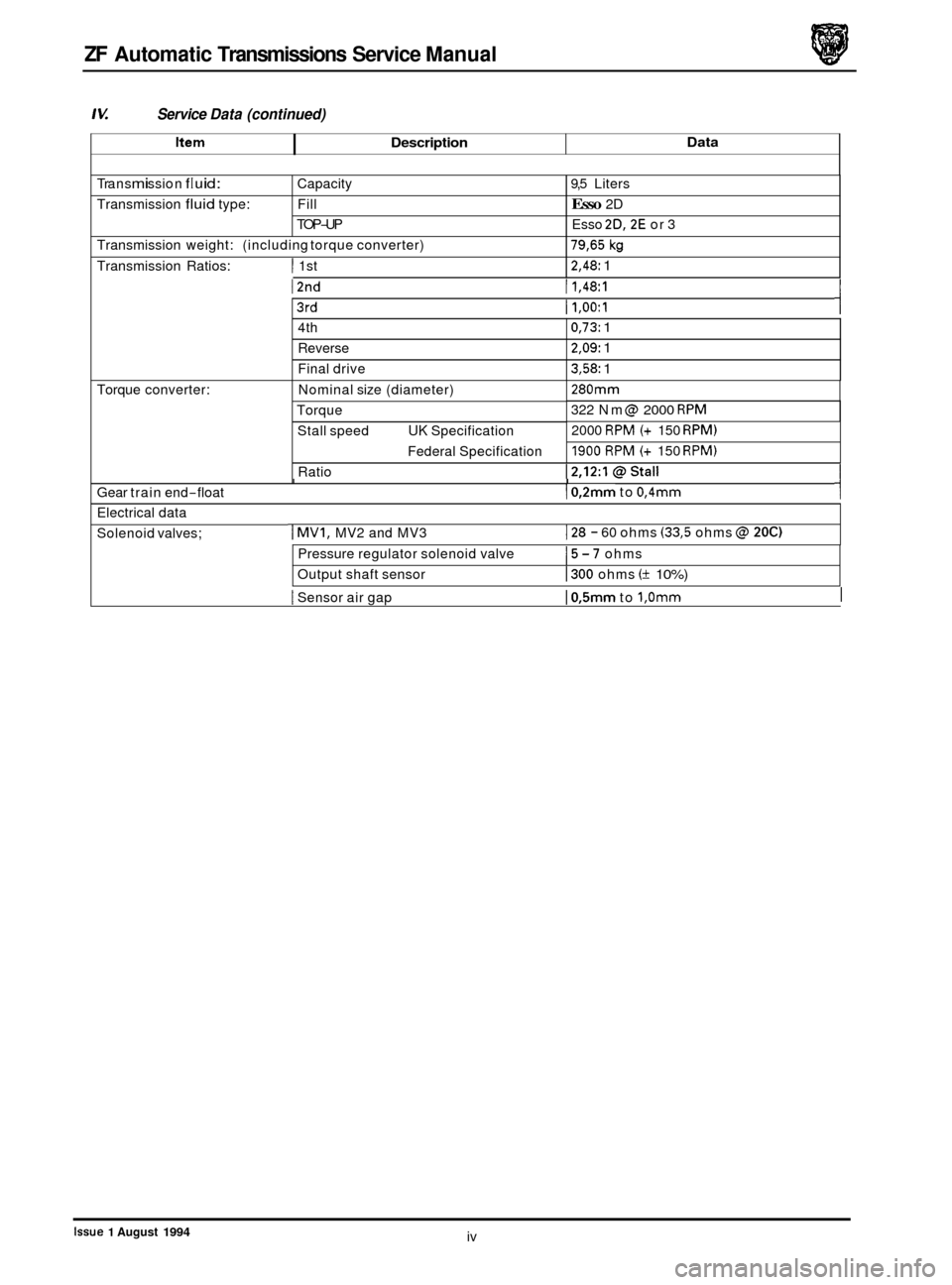
Tra ns m i ssi on f I u i d :
Transmission fluid type: Capacity
9,5 Liters
Fill Esso 2D
TOP
-UP Esso 2D,2E or 3
Torque converter:
Transmission
weight: (including torque converter)
Transmission Ratios:
I 1st
I2nd
79,65 kg
2,48: 1
I1,48:1
4th
Reverse
Final drive
I3rd
0,73: 1
2,09: 1
3,58: 1
I1,OO:l
Nominal size (diameter)
Torque Stall speed
UK Specification
Federal Specification
280mm
322 Nm @ 2000 RPM
2000 RPM (+ 150 RPM)
1900 RPM (+ 150 RPM)
Ratio I I Gear train end-float I0,2mm to 0,4mm
Electrical data
Solenoid valves;
I MV1, MV2 and MV3 I28 - 60 ohms (33,5 ohms @ 200
Pressure regulator solenoid valve
Output shaft sensor 15-7 ohms
I300 ohms (+ 10%)
I Sensor air gap I0,5mm to 1,Omm I
iv Issue 1 August 1994
Page 45 of 74
ZF Automatic Transmissions Service Manual
The torque converter acts in all four forward gears and in reverse. The converter lock-up clutch closes in 4th gear at
a point depending on road speed and accelerator position; engine power is then transmitted
by purely mechanical
means.
A low
-loss oil pump in the front of the transmission housing supplies the converter, the automatic gear shift and the
lubrication circuit; oil is drawn from a sump in the bottom of the gear train housing through a filter. The pump drive
gear is keyed to the converter impeller hub and therefore turns when the engine is running, thereby pressurizing the
oil.
2.1.2 Four-speed Epicyclic Gear Train
The torque converter drives a mechanical epicyclic gear train providing four forward ratios and reverse. Individual ra-
tios are obtained by coupling together the various parts of the gear train by means of solenoid-operated, hydraulically
actuated multi-disc clutches and brakes; built in freewheels permit gear shifts without any interruption of the power
flow.
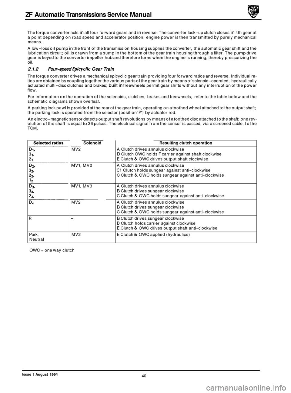
For information on the operation of the solenoids, clutches, brakes and freewheels, refer to the table below and the
schematic diagrams shown overleaf.
A parking lock pawl is provided at the rear of the gear train, operating on a toothed wheel attached to the output shaft;
the parking lock is operated from the selector (position
'P) by actuator rod.
An electro
-magnetic sensor detects output shaft revolutions by means of a toothed disc attached to the shaft; one rev- olution of the shaft is equal to 36 pulses. The electrical signal from the sensor is passed, via a screened cable, to the
TCM.
R
Park,
Neutral
Solenoid ~
MV2
MVI, MV2
MVI, MV3
MV2
-
MV2
OWC
= one way clutch
Resulting clutch operation
A Clutch drives annulus clockwise
D Clutch OWC holds F carrier against shaft clockwise
E Clutch & OWC drives output shaft clockwise
A Clutch drives annulus clockwise
C1 Clutch holds sungear against anti-clockwise
C Clutch
& OWC holds sungear against anti-clockwise
A Clutch drives annulus clockwise
B Clutch drives sungear clockwise
C Clutch
& OWC holds sungear against anti-clockwise
A Clutch drives annulus clockwise
B Clutch drives sungear clockwise
C Clutch
& OWC holds sungear against anti-clockwise
B Clutch drives sungear clockwise
D Clutch holds carrier against clockwise
E Clutch & OWC drives output shaft anti-clockwise
E Clutch & OWC applied (hydraulics)
40
Issue 1 August 1994
Page 52 of 74

4
AFLR M- -1
4 13 9
14
15 7
J44-718
1.
Selector 2. Mode switch 3. Rotary switch
4. Transmission control unit 5. Output shaft speed sensor 6. Kick-down switch 7. Battery
8. Transmission relay
9.
10.
11.
12.
13.
14.
15.
16.
Transmission control module (TCM)
Reverse lamps
Start inhibiter
Engine speed
Ignition retard
Engine load
Engine control module
(ECM) Engine speed sensor
Fig.
1 Control Layout Schematic
2.1.5 Transmission Control Module (TCM)
The Transmission Control Module (TCM) is an electronic control unit located in the front passenger footwell behind
the underscuttle pad. It is electrically connected to the transmission and other components through a cable harness
and multiple pin plug.
The TCM continuously monitors the gear selected (via the rotary transmission switch), the speed of the output shaft
(by speed sensor on the output shaft) and throttle position ('kick
-down' switch). This information plus input from the
Engine Control Module (ECM) of throttle angle and engine speed and load in conjunction with a pre-programmed con- trol map, enables the most suitable gear to be selected.
The TCM, by operating solenoid valves
MVI, MV2 and MV3, controls the gear shift speed and in conjunction with the
solenoid operated pressure control valve, controls the gear shift quality. Gear shift quality on upshifts is improved by
the TCM momentarily retarding the ignition to reduce the torque input as the gear change takes place. Information
is fed to the TCM from sensors and
if any electronic component fails, the basic shift changes will be performed by the
hydro-mechanical system, ie Park, Reverse, Neutral, D3 or D4.
46
Issue 1 August 1994
Page 53 of 74
ZF Automatic Transmissions Service Manual
Vehicle speed sensor plus input
Engine speed input
Program switch input
Solenoid valve
MVI output
Pressure control valve PCV output
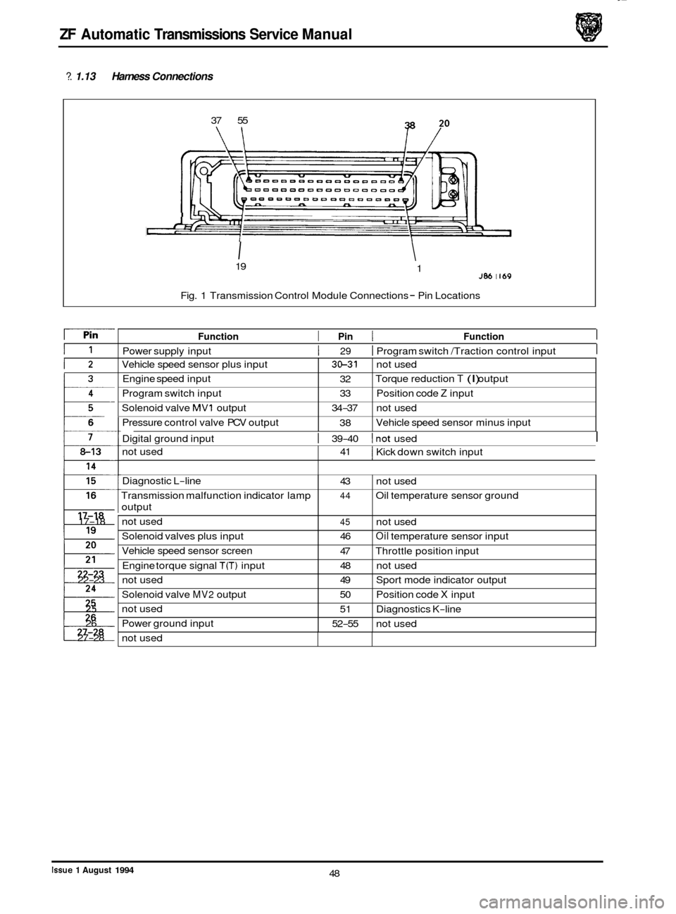
?. 1.13 Harness Connections
3&31 not used
32
33 Position code
Z input
38 Torque
reduction
T (I) output
34
-37 not used
Vehicle speed sensor minus input
37
55
not used
\I
41 I Kick down switch input
J" i"
Diagnostic L-line
Transmission malfunction indicator lamp
output
not used
Solenoid valves plus input
Vehicle speed sensor screen
Engine torque signal
T(T) input
I IU,MW II
43 not used
44 Oil temperature sensor ground
45 not used
46
Oil temperature sensor input
47 Throttle position input
48 not used
I
not used
Solenoid valve
MV2 output
not used
Power ground input 19
49 Sport mode indicator output
50 Position code X input
51 Diagnostics K
-line
52
-55 not used
J86 I I69 1
Fig.
1 Transmission Control Module Connections - Pin Locations
I1
12
13
: I
17-18
22
-23
t 27-28
25
26
Function I Pin I Function I
Power supply input I 29 I Program switch /Traction control input I
Digital ground input I 39-40 lnot used I
not used
-~
48 Issue 1 August 1994
Page 54 of 74

ZF Automatic Transmissions Service Manual
N
B
W
K
G
R
2.1.14 Rotary Switch Harness
Brown Y Yellow
Black
0 Orange
White
S Slate
Pink
L Light
Green
P Purple
Red
U Blue
Fig.
1 Transmission Connector (%way)
temperature
sensor
Color Code
I I /Indigo II I
Issue 1 August 1994 49
Page 68 of 74
ZF Automatic Transmissions Service Manual
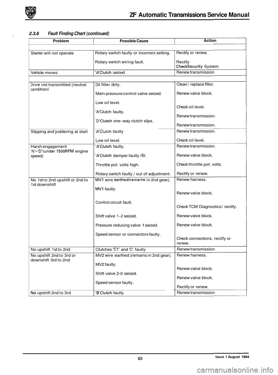
Problem Possible Cause
2.3.6 Fault Finding Chart (continued)
e Action
Starter will not operate Rotary
switch faulty or incorrect setting. Rectify
or renew.
3rive not transmitted (neutral
:ondition)
Vehicle moves
Slipping and juddering at start Rotary
switch wiring fault. Rectify 'A'Clutch seized Renew
transmission
Checksecurity System
Harsh engagement
'N'-'D'(under 1500RPM engine
speed)
No 1st to 2nd upshift or 2nd to
1st downshift
No upshift 1st to 2nd
No upshift 2nd to 3rd or
downshift 3rd to 2nd
No upshift 2nd to 3rd
3il filter dirty.
Main pressure control valve seized.
Low oil level.
'A'Clutch faulty.
'D'Clutch one-way clutch slips. ~
'A'Clutch faulty
Low oil level.
'A'Clutch faulty.
'A'Clutch damper faulty (5).
Throttle pot. volts high.
Rotary switch faulty
/ out of adjustment.
MVI wire earthed(remains in 2nd gear).
MVI faulty.
Control circuit fault.
Shift valve
1-2 seized.
Pressure reducing valve
1 seized.
Speed sensor or connectors faulty.
Clutches
'Cl' and 'C' faulty
MV2 wire earthed (remains in 2nd gear).
MV2 faulty.
Shift valve 2
-3 seized.
Speed sensor faulty.
'B'Clutch faulty Clean
/ replace
filter.
Renew valve block.
Check oil level.
Renew transmission.
Renew transmission.
Renew transmission.
Check oil level.
Renew transmission.
Renew valve block.
Check throttle pot. volts.
Rectify or renew.
Renew harness.
Renew valve block.
Check TCM Diagnostics
/ rectify.
Renew valve block.
Renew valve block.
Check connections, rectify or
renew.
Renew transmission
Renew harness.
Renew valve block.
Renew valve block.
Rectify or renew.
Renew transmission
Issue 1 August 1994 63
Page 69 of 74

ZF Automatic Transmissions Service Manual
0
2.3.6 Fault Finding Chart (continued)
Problem
Uo upshift 3rd to 4th or
lownshift 4th to 3rd
Vo upshift 3rd to 4th
lownshift 4th to 3rd too hard
Manual gearshift D to 3rd too
lard
Manual gearshift 3rd to 2nd too
9ard
Vo 1st gear; 2nd gear start only.
No 1st or 2nd gear; 3rd gear
start only
No 2nd gear; transmission shifts
1st to 3rd gear
Light throttle gear change
speeds incorrect
Up to 'kick
-down' detent, gear
change speeds not to
specification
Possible Cause
Shift valve 3-4 seized.
MVl wire earthed.
MV1 faulty.
Speed sensor faulty.
'F'Clutch faulty
3rain orifice 'F' partially blocked.
Damper
'E' faulty.
Damper
'E' faulty.
Drain orifice
'F' partially blocked.
Damper
'Cl' faulty
Speed sensor faulty.
MV1 faulty.
MV1 wire earthed.
Shift valve 1
-2 seized.
'1st Gear Inhibit' circuit operated or
'Performance Mode' switch faulty.
Transmission 'Limp Home' mode.
Speed sensor faulty.
MV1 or MV2 faulty.
Shift valves 1
-2 and 2-3 seized.
Speed sensor faulty.
Shift valve 2
-3 seized.
Shift valves sticking.
Speed sensor faulty.
Throttle pot. volts incorrect.
Transmission Control Module
(TCM).
'Kick-down' switch out of adjustment
3enew valve block.
3enew harness.
Renew valve block.
Rectify or renew.
Renew transmission
Renew valve block.
Renew valve block.
Renew valve block.
Renew valve block.
Renew valve block
Check or renew speed sensor.
Renew valve block.
Renew harness.
Renew valve block.
Operate 'Performance Mode' switch
to correct function or renew switch.
Check Diagnostics
1 JDS.
Renew speed sensor.
Renew valve block.
Renew valve block.
Check or
recheck Diagnostics,
renew speed sensor.
Renew valve block.
Renew valve block.
Check or renew speed sensor.
Check voltage
- JDS.
Check TCM Diagnostics.
Readjust 'kick
-down' switch
Issue 1 August 1994 64
Page 70 of 74
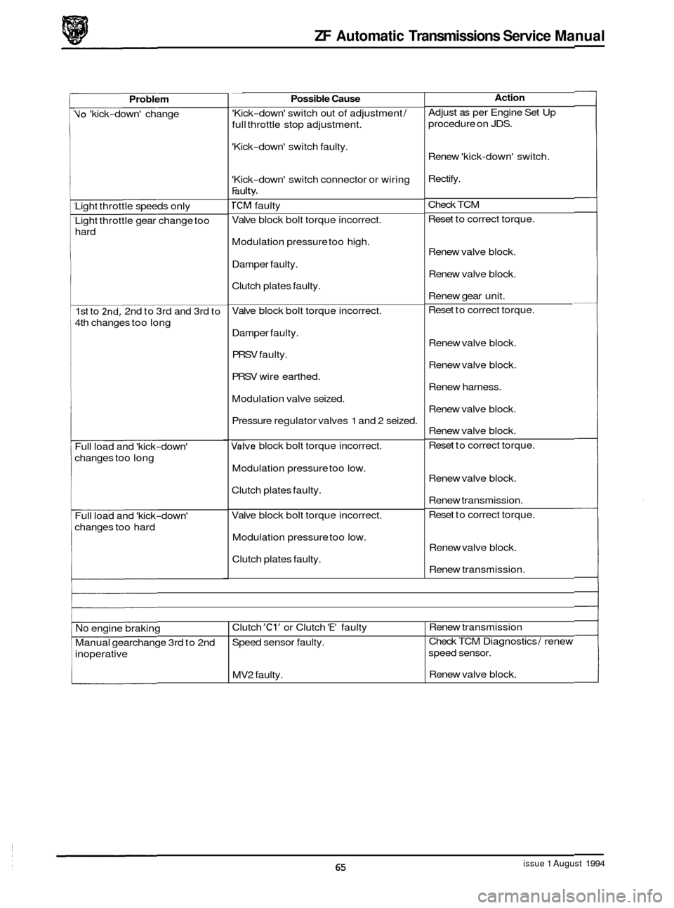
ZF Automatic Transmissions Service Manual
No engine braking
Manual gearchange 3rd to 2nd
inoperative Clutch 'Cl' or
Clutch 'E' faulty
Speed sensor faulty.
MV2 faulty.
a
Renew transmission
Check TCM Diagnostics
1 renew
speed sensor.
Renew valve block.
a
0
Problem
Vo 'kick-down' change
Light throttle speeds only
Light throttle gear change too
hard
1st to
2nd, 2nd to 3rd and 3rd to
4th changes too long
Full load and 'kick
-down'
changes too long
Full load and 'kick
-down'
changes too hard ~
Possible Cause
'Kick-down'
switch out of adjustment 1
full throttle stop adjustment.
'Kick
-down' switch faulty.
'Kick
-down' switch connector or wiring
Fa u Ity.
TCM faulty
Valve block bolt torque incorrect.
Modulation pressure too high.
Damper faulty.
Clutch plates faulty.
Valve block bolt torque incorrect.
Damper faulty.
PRSV faulty.
PRSV wire earthed.
Modulation valve seized.
Pressure regulator valves
1 and 2 seized.
mve block bolt torque incorrect.
Modulation pressure too low.
Clutch plates faulty.
Valve block bolt torque incorrect.
Modulation pressure too low.
Clutch plates faulty.
Action
Adjust as per Engine Set Up
procedure on JDS.
Renew 'kick
-down' switch.
Rectify.
Check TCM
Reset to correct torque.
Renew valve block.
Renew valve block.
Renew gear unit.
Reset to correct torque.
Renew valve block.
Renew valve block.
Renew harness.
Renew valve block.
Renew valve block.
Reset to correct torque.
Renew valve block.
Renew transmission.
Reset to correct torque.
Renew valve block.
Renew transmission.
issue 1 August 1994 65
Page 71 of 74
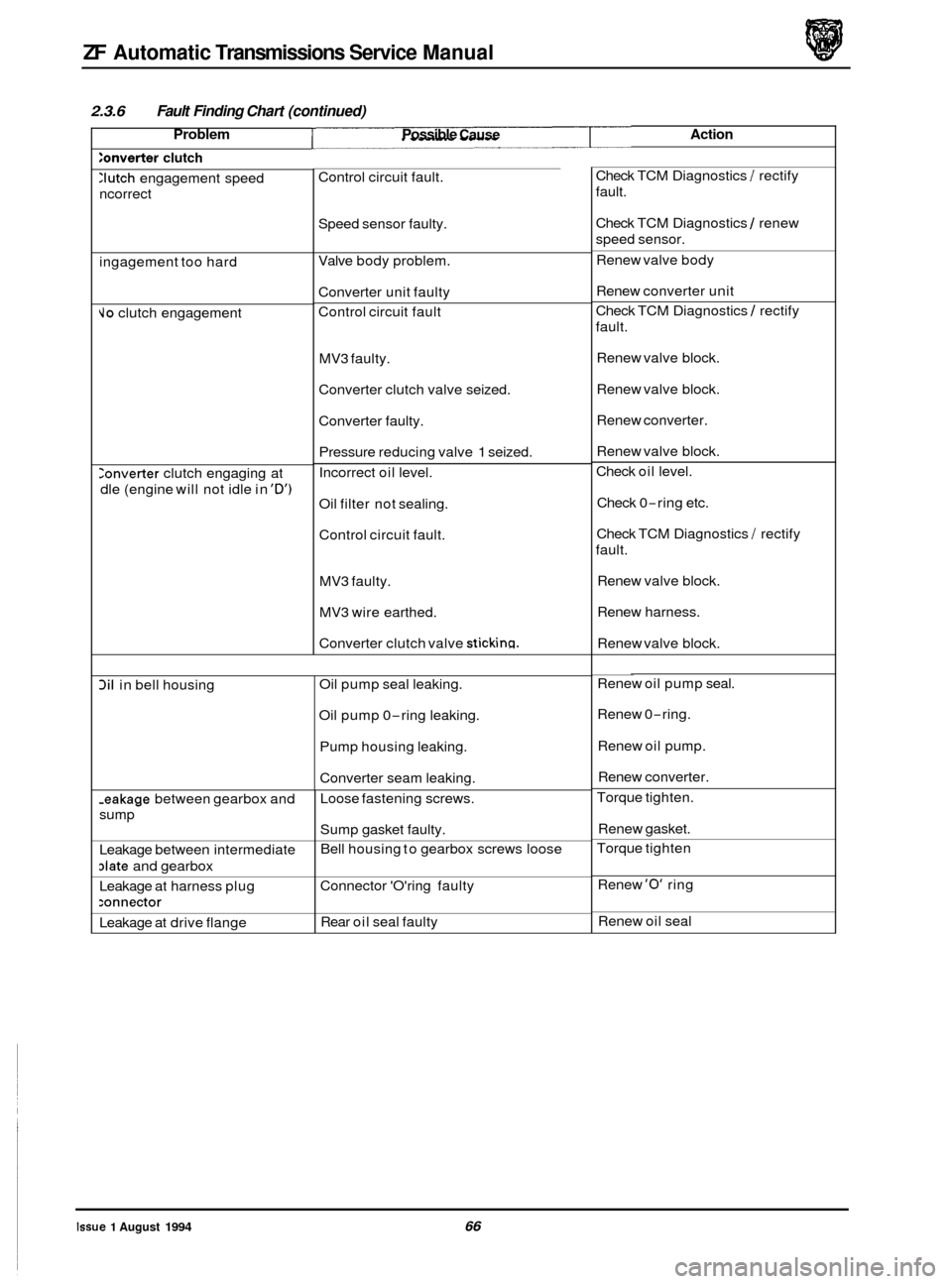
ZF Automatic Transmissions Service Manual
0
3il in bell housing
2.3.6 Fault Finding Chart (continued)
Oil pump seal leaking.
Oil pump 0
-ring leaking.
Pump housing leaking.
Converter seam leaking.
Problem Possible Cause Action
:onverter clutch
-eakage between gearbox and
sump
Leakage between intermediate
date and gearbox
Leakage at harness plug
:onnector
Leakage at drive flange
:Iutch engagement speed
ncorrect
Loose fastening screws.
Sump gasket faulty.
Bell housing to gearbox screws loose
Connector 'O'ring faulty
Rear oil seal faulty
ingagement
too hard
Jo clutch engagement
Ionverter clutch engaging at
dle (engine will not idle in
'D')
Control circuit fault.
Speed sensor faulty.
Valve body problem.
Converter unit faulty
Control circuit fault
MV3 faulty.
Converter clutch valve seized.
Converter faulty. Pressure reducing valve
1 seized.
Incorrect oil level.
Oil filter not sealing.
Control circuit fault.
MV3 faulty.
MV3 wire earthed.
Converter clutch valve
sticking.
Check TCM Diagnostics / rectify
fault.
Check TCM Diagnostics
1 renew
speed sensor.
Renew valve body
Renew converter unit
Check TCM Diagnostics
1 rectify
fault.
Renew valve block.
Renew valve block.
Renew converter.
Renew valve block.
Check oil level.
Check 0
-ring etc.
Check TCM Diagnostics
/ rectify
fault.
Renew valve block.
Renew harness.
Renew valve block.
Renew oil pump seal.
Renew 0
-ring.
Renew oil pump.
Renew converter.
Torque tighten.
Renew gasket.
Torque tighten
Renew
'0' ring
Renew oil seal
Issue 1 August 1994 66
. _.~ -