change time JAGUAR XJ 2004 X350 / 3.G Owners Manual
[x] Cancel search | Manufacturer: JAGUAR, Model Year: 2004, Model line: XJ, Model: JAGUAR XJ 2004 X350 / 3.GPages: 227, PDF Size: 4.22 MB
Page 2 of 227
JAGUAR CARS LIMITED, as manufacturer, is dedicated to the
design and production of vehicles which meet the expectations
of the world’s most discerning purchasers.
This handbook forms part of th e owner literature supplied with
your vehicle. It is designed to co mplement the relevant features
and systems of the vehicle, and make them easy to understand
and operate.
The information contained in this handbook applies to a range
of vehicles and not to a specific vehicle. For the specification of
a particular vehicle, owners should consult their Jaguar Retailer.
The manufacturer reserves the ri ght to vary its specifications
with or without notice, and at su ch times and in such manner as
it thinks fit. Major as well as minor changes may be involved in
accordance with the Manufacturer ’s policy of constant product
improvement.
To cover changes, it is sometimes necessary to issue one or
more handbook supplements. When reading this handbook,
check the owner literature for possible supplements.
For full details of the owner litera ture originally supplied with
the vehicle, owners should consult their Jaguar Retailer. All rights reserved. No part of this publication may be
reproduced, stored in a retrieval system or transmitted, in any
form, electronic, mechanical, pho
tocopying, recording or other
means without prior writte n permission from the
Service Division of Jaguar Cars Limited.
Page 12 of 227
1 - 8 Owner Information
Regular Servicing
Each vehicle is given a full ‘Pre-Delivery
Inspection’ to ensure that all systems
function correctly and that the vehicle
meets its specification.
Owners are responsible for the regular
maintenance and servicing of the vehicle.
Jaguar Retailers will be pleased to arrange
periodic servicing and can provide you
with details of tasks carried out at each
service interval.
Failure to implement maintenance at the
recommended interval s could result in
deterioration of vehicle performance and
possible infringement of regulations.
Regular routine maintenance not only
helps to prevent unnecessary
‘breakdowns’ and inconvenience,
but enhances the ‘trade in’ or resale
value of the vehicle.
Failure to perform regular maintenance at
the correct interval may void the factory
warranty.
USA and Canada
Jaguar Retailers will arrange for
appointments on a mileage/kilometre or
time interval basis to ensure that all
routine and corrective maintenance work
is undertaken and recorded in the
‘Passport to Service’ Booklet. This booklet
not only contains a record of vital
information, but also information about
warranties, Jaguar Cars, Jaguar Car Clubs,
Tyre Manufacturers and change of
ownership or address vouchers.
Mexico
Jaguar Retailers will arrange for
appointments on a mileage/distance or
time interval basis to ensure that all
routine and corrective maintenance work
is undertaken and recorded in the Service
Record and Warranty Book. This booklet
not only contains a record of vital
information, but also information about
warranty and a change of ownership
card.
Jaguar Diagnostic System
Many of the vehicle systems are
controlled by complex electronic devices.
Specialist equipment is required to trace
and rectify faults in the systems and
ensure that only faulty components are
repaired or renewed.
Caution: Severe damage to the
electrical system and electronic
components can occur if any attempt
is made to diagnose faults in the
electrical system using conventional
diagnostic equipment (for example;
the use of test lamps or low
impedance voltmeters ). The fitting of
any electrical accessory should only
be entrusted to a Jaguar Retailer.
Page 32 of 227
Security and Locks 2 - 17
Security Features
The security system has been designed
for:
• Prevention of theft of the vehicle.
• Prevention of theft of items from the vehicle.
• Personal security.
The security system is integrated with the
vehicle electronics and engine
management systems making it far more
difficult for a thief to penetrate and steal
the vehicle.
Panic Alarm (if enabled)
When in or near the vehicle, the alarm
can be set off to dete r a possible offender.
For this feature to operate, the key must
not be in the ignition switch.
Pressing the headlamp convenience/panic
button on the key transmitter three times
within three seconds will activate the
‘Panic Alarm’.
The alarm is stopped by:
• Putting the key into the ignition switch and turning to position ‘II’.
Note:
1. The key transmitter cannot be used to cancel the Panic alarm. This prevents
unauthorised cancellation in an
emergency.
2. The panic alarm is normally enabled. If required, this feature can be
disabled or enabled by a Jaguar
Retailer.
3. The vehicle locking status will not change when the panic alarm is
activated.
Passive Arming (Retailer
Option)
Passive arming wi ll not lock the
doors, it only arms the security alarm
system.
Passive arming, if enabled by a Jaguar
Retailer, will automatically arm the
vehicle alarm system 30 seconds after the
last protected entry (door, luggage
compartment) is closed following the key
being removed from th e ignition switch.
When passive arming occurs the direction
indicators will flash once and a single
tone will be heard (if enabled). The red
security light on the fascia will start to
flash and will continue for as long as the
alarm is armed.
Opening the drivers door causes a
warning sound which continues for
15 seconds before the system goes into
the full alarm state. If any other door is
opened before the drivers door,
the system goes into the full alarm state
immediately.
When the system is pa ssively armed and a
key is used to open the trunk, a seven
second warning audible ticking will
sound before the full alarm is activated.
Page 37 of 227
2 - 22 Security and Locks
3. Using both hands, simultaneously press and hold both the desired garage
door opener button on the overhead
console and the hand -held transmitter
button. Keep both buttons pressed.
The light will flash, slowly at first and
then change to a fast flash. When the
indicator light flashes rapidly, release
both buttons. The rapid flashing light
indicates successful programming.
4. If, after 60 seconds, the indicator light does not flash rapidl y, release both the
transceiver and the hand-held
transmitter buttons and repeat the
procedure starting with Step 2.
However, position the hand-held
transmitter at a different angle and/or
distance.
5. Press and hold the programmed overhead console garage door opener
button and observe the indicator light:
• If the indicator light is solid/continuous, programming is
complete. Your device should
activate when the garage door
opener button is pressed and held
for 1 to 2 seconds and then
released. • If the indicator light blinks rapidly
for 2 seconds and then turns a
solid/continuous light, proceed
with the following programming
instructions for ‘rolling code’
device equipment.
Note: To programme additional garage
door opener buttons, begin at Step 2.
Rolling code device equipment
programming
Note: A second person may make the
following steps quicker and easier as once
the button has been pressed there are
30 seconds only in which to complete
Step 3.
1. At the garage door opener receiver (motor head unit) in the garage, locate
the ‘learn’ or ‘smart’ button/switch.
Note: The name of the button/switch
may vary between manufacturers.
2. Press and release the ‘learn’ or ‘smart’ button.
3. Return to the vehicle and firmly press and hold the programmed garage door
opener button for 2 seconds and
release. 4. Repeat the press/hold/release
sequence 3 times to complete the
learning/training process.
The garage door opener in the overhead
console should now activate the ‘rolling
code’ device.
Reprogramming a sing le garage door
opener button
To programme a device to a previously
trained button:
1. Press and hold the desired pre- programmed garage door opener
button for at least 20 seconds, but no
longer than 30 seconds, until the
indicator light begins to flash.
2. Without releasing the overhead console button, position the hand-
held transmitter approximately 2 to
6 inches (5 cm to 15 cm) away from
the transceiver in the overhead
console, keeping the indicator light in
view.
3. Carry out Step 3 of programming the vehicle, see column 1.
Page 61 of 227
3 - 22 Before Driving
Driving Position
!WARNING:
Driver and front seat passenger
should always move their seats as far
rearwards as is practical.
Ideally, drivers should sit with at least
10 inches (25.4 cm) between the centre
of their breastbone and the cover of the
steering wheel air bag.
Since the risk zone at the time of
deployment is the first 2 to 3 inches
(5.5 cm – 7.5 cm) from the air bag cover,
sitting back 10 inches (25.4 cm) provides
a clear margin of safety. Very few drivers
are unable to achieve and maintain that
safety gap. The vast majority of drivers who do not
now sit that far back can change their
position and achieve that distance.
• If adjustable pedals are fitted, move
them towards the seat.
• Move your seat back as far as you can while still comfortably reaching the
pedals.
• Recline the back of your seat one or two notches from the upright
position. If reclining the back of your
seat makes it hard to see the road,
raise the seat.
• Tilt the steering wheel/column downwards so as to point the air bag
at your chest instead of your head and
neck. Adjust the steering wheel/
column fore/aft so that it extends
towards the driver as little as possible,
ensuring that the air bag has plenty of
room to deploy.
• Sit in the centre of the seat with the head as close to the head restraint as
possible. Note:
Seat, steering wheel and pedal
adjustment controls are described
elsewhere in this section.
Page 83 of 227
4-12 On the Road
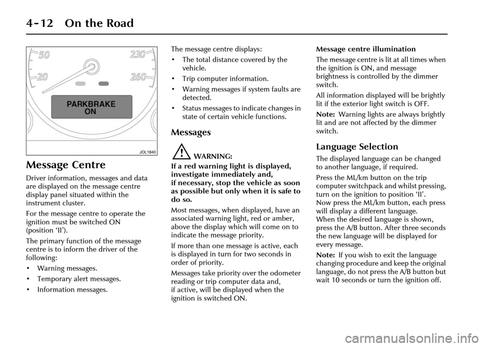
Message Centre
Driver information, messages and data
are displayed on the message centre
display panel situated within the
instrument cluster.
For the message centre to operate the
ignition must be switched ON
(position ‘II’).
The primary function of the message
centre is to inform the driver of the
following:
• Warning messages.
• Temporary alert messages.
• Information messages.The message centre displays:
• The total distance covered by the
vehicle.
• Trip computer information.
• Warning messages if system faults are detected.
• Status messages to indicate changes in
state of certain vehicle functions.
Messages
!WARNING:
If a red warning light is displayed,
investigate immediately and,
if necessary, stop the vehicle as soon
as possible but only when it is safe to
do so.
Most messages, when displayed, have an
associated warning light, red or amber,
above the display which will come on to
indicate the message priority.
If more than one message is active, each
is displayed in turn for two seconds in
order of priority.
Messages take priority over the odometer
reading or trip computer data and,
if active, will be displayed when the
ignition is switched ON. Message centre illumination
The message centre is lit at all times when
the ignition is ON, and message
brightness is controlled by the dimmer
switch.
All information displayed will be brightly
lit if the exterior light switch is OFF.
Note:
Warning lights are always brightly
lit and are not affected by the dimmer
switch.
Language Selection
The displayed language can be changed
to another language, if required.
Press the ML/km button on the trip
computer switchpack and whilst pressing,
turn on the ignition to position ‘II’.
Now press the ML/km button, each press
will display a different language.
When the desired language is shown,
press the A/B button. After three seconds
the new language will be displayed for
every message.
Note: If you wish to exit the language
changing procedure and keep the original
language, do not press the A/B button but
wait 10 seconds or turn the ignition off.
Page 115 of 227
4-44 On the Road
Note:
1. After selecting forward or reverse drive ranges from Neutral or Park,
wait briefly for th e transmission to
engage before accelerating.
2. When in Neutral or Park the engine can only be a ccelerated to
4500 rev/min.
R = Reverse – Do not select if the vehicle
is moving forward.
The reversing lights come ON
automatically when reverse gear is
selected and the ignition switch is in
position ‘II’.
D = Drive – All six gears are changed
automatically as required by the throttle
position and road speed.
2, 3, 4, 5 = If selected, the transmission
operates automatically in second, third,
fourth or fifth gear but will not engage
gears higher than the one selected. Drive to fifth
When driving in gear position ‘D’ with
sixth gear engaged, the gear selector can
be shifted sideways across the gate to ‘
5’.
Provided that the vehicle’s speed is not
too great, the transmission will shift
down to fifth. Sixth gear will be inhibited
until the gear selector is moved back to
‘D’.
Hill climbing and engine braking
When driving on roads with long
downhill gradients, selecting ‘3’ or ‘2’
(depending on road/traffic conditions)
will give engine braking.
When the gear selector is moved
from ‘D’, ‘5’, ‘4’ or ‘3’ down to ‘2’,
downshift to second ge ar will only take
place at appropriate road speeds.
Reverse inhibit
Reverse is inhibited when the vehicle is
moving forward at speeds above 5 mph
(8 km/h).
Note: Reverse inhibit will not function in
limp-home mode. Kickdown
Kickdown is operated when the pedal is
pressed fully down, beyond the normal
operating range and against a spring
pressure, to provide maximum engine
performance. Kickdown is used in
circumstances where rapid acceleration is
required, such as when overtaking.
Kickdown causes the transmission to
change down to the lowest gear possible
to achieve maximum acceleration.
The gear engaged depends on the road
speed at the time of kickdown.
As well as shifting
down, the gearshift
points are extended to give greater
performance. This mode is in effect for as
long as the pedal is pressed fully down.
Page 124 of 227
On the Road 4 - 53
When a vehicle ahead enters the same
lane or a slower vehicle is ahead in the
same lane, the vehicle speed will be
adjusted automatically until the gap to
the vehicle ahead corresponds to the
preset gap. The vehicle is now in ‘follow
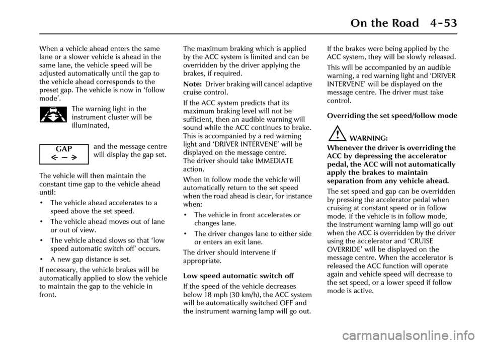
mode’.The warning light in the
instrument cluster will be
illuminated,
and the message centre
will display the gap set.
The vehicle will then maintain the
constant time gap to the vehicle ahead
until:
• The vehicle ahead accelerates to a speed above the set speed.
• The vehicle ahead moves out of lane or out of view.
• The vehicle ahead slows so that ‘low speed automatic switch off’ occurs.
• A new gap distance is set.
If necessary, the vehicle brakes will be
automatically applied to slow the vehicle
to maintain the gap to the vehicle in
front. The maximum braking which is applied
by the ACC system is limited and can be
overridden by the driver applying the
brakes, if required.
Note:
Driver braking will cancel adaptive
cruise control.
If the ACC system predicts that its
maximum braking level will not be
sufficient, then an audible warning will
sound while the ACC continues to brake.
This is accompanied by a red warning
light and ‘DRIVER INTERVENE’ will be
displayed on the message centre.
The driver should take IMMEDIATE
action.
When in follow mode the vehicle will
automatically return to the set speed
when the road ahead is clear, for instance
when:
• The vehicle in front accelerates or changes lane.
• The driver changes lane to either side or enters an exit lane.
The driver should intervene if
appropriate.
Low speed automatic switch off
If the speed of the vehicle decreases
below 18 mph (30 km/h), the ACC system
will be automatically switched OFF and
the instrument warning lamp will go out. If the brakes were
being applied by the
ACC system, they will be slowly released.
This will be accompanied by an audible
warning, a red warning light and ‘DRIVER
INTERVENE’ will be displayed on the
message centre. The driver must take
control.
Overriding the set speed/follow mode
!WARNING:
Whenever the driver is overriding the
ACC by depressing the accelerator
pedal, the ACC will not automatically
apply the brakes to maintain
separation from any vehicle ahead.
The set speed and gap can be overridden
by pressing the accelerator pedal when
cruising at constant speed or in follow
mode. If the vehicle is in follow mode,
the instrument warning lamp will go out
when the ACC is overridden by the driver
using the accelera tor and ‘CRUISE
OVERRIDE’ will be displayed on the
message centre. When the accelerator is
released the ACC function will operate
again and vehicle speed will decrease to
the set speed, or a lower speed if follow
mode is active.
GAP
Page 126 of 227
On the Road 4 - 55
Forward alert
Limited detection and warning of objects
ahead is provided during ACC operation
by the ACC ‘DRIVER INTERVENE’
warning.
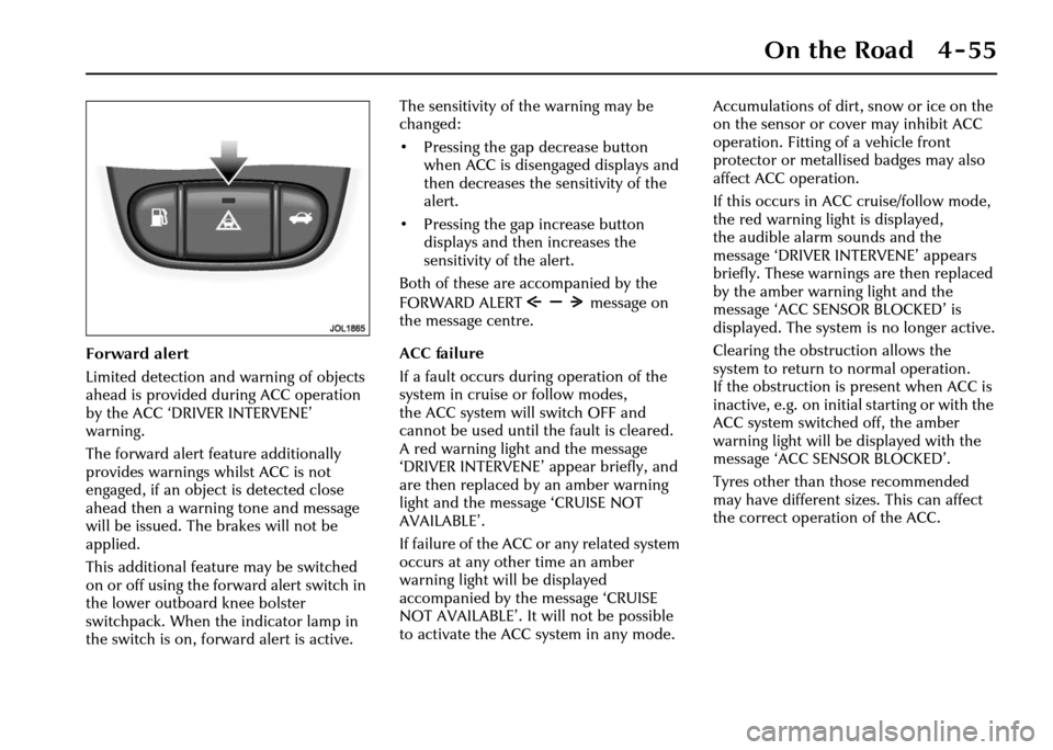
The forward alert feature additionally
provides warnings whilst ACC is not
engaged, if an object is detected close
ahead then a warning tone and message
will be issued. The brakes will not be
applied.
This additional feature may be switched
on or off using the forward alert switch in
the lower outboard knee bolster
switchpack. When the indicator lamp in
the switch is on, forward alert is active.The sensitivity of the warning may be
changed:
• Pressing the gap decrease button
when ACC is disengaged displays and
then decreases the sensitivity of the
alert.
• Pressing the gap increase button displays and then increases the
sensitivity of the alert.
Both of these are accompanied by the
FORWARD ALERT message on
the message centre.
ACC failure
If a fault occurs during operation of the
system in cruise or follow modes,
the ACC system will switch OFF and
cannot be used until the fault is cleared.
A red warning light and the message
‘DRIVER INTERVENE’ appear briefly, and
are then replaced by an amber warning
light and the message ‘CRUISE NOT
AVAILABLE’.
If failure of the ACC or any related system
occurs at any other time an amber
warning light will be displayed
accompanied by th e message ‘CRUISE
NOT AVAILABLE’. It will not be possible
to activate the ACC system in any mode. Accumulations of dirt, snow or ice on the
on the sensor or cover may inhibit ACC
operation. Fitting of a vehicle front
protector or metallis
ed badges may also
affect ACC operation.
If this occurs in ACC cruise/follow mode,
the red warning light is displayed,
the audible alarm sounds and the
message ‘DRIVER INTERVENE’ appears
briefly. These warnings are then replaced
by the amber warning light and the
message ‘ACC SENSOR BLOCKED’ is
displayed. The system is no longer active.
Clearing the obstruction allows the
system to return to normal operation.
If the obstruction is present when ACC is
inactive, e.g. on initial starting or with the
ACC system switched off, the amber
warning light will be displayed with the
message ‘ACC SENSOR BLOCKED’.
Tyres other than those recommended
may have different sizes. This can affect
the correct operation of the ACC.
Page 129 of 227
4-58 On the Road
Vehicle Suspension
This vehicle is fitted with a fully
automatic air suspension system.
It ensures that the vehicle is always at the
correct ride height with varying load
conditions, including luggage
compartment load or when towing.
The system will automatically adjust the
amount of air in the springs to level the
vehicle. Air is supplied either from an air
reservoir or a compressor.
The compressor will run periodically to
refill the reservoir.
Changes in ambient temperature will also
have an effect on vehicle height when the
vehicle is parked.
Caution:
1. Do not overload the vehicle. Vehicle load weights are shown
on page 8 - 4.
2. A slight air loss is expected over time causing the vehicle to lower,
so do not store or place anything
under the vehicle if it is to be left
for an extended period. Speed lowering
When driving at motorway speeds,
the system will lower the vehicle to
improve aerodynamics and vehicle
stability. The suspension will
automatically return the vehicle to the
normal height when the vehicle slows.
Caution: Speed lowering is
undesirable when towing.
Only Jaguar approved towing
equipment will not allow this feature.
Warning messages
If the message ‘VEHICLE TOO LOW’ is
displayed when the ignition is switched
on, start the engine and wait for the
suspension to raise. The vehicle should
not be driven until the message is
cleared.
If the message ‘VEHICLE TOO LOW’ is
displayed when driv
ing, restrict the
vehicle speed and wait for the system to
regain the correct height and the message
will then clear. If the message is displayed
frequently, it is advisable to inform your
Retailer to have the system attended to.
If the message ‘AIR SUSPENSION FAULT’
is displayed at any time, drive with
caution. Have the vehicle checked by a
Retailer at the earliest opportunity.
Note: If your vehicle needs to be
recovered by a roadside emergency
service ensure that the vehicle is securely
lashed by the wheels and NOT the body.