remove seats JEEP CHEROKEE 1988 Service Repair Manual
[x] Cancel search | Manufacturer: JEEP, Model Year: 1988, Model line: CHEROKEE, Model: JEEP CHEROKEE 1988Pages: 1378, PDF Size: 19.9 MB
Page 331 of 1378

Remove axle shaft oil seal from axle housing tube.
3) Place axle shaft in a vise. Drill a 1/4" (6.35 mm) hole
3/4 of the way through bearing retaining ring. Chisel off bearing
retaining ring. Do not use a torch. Press bearing off axle. Remove
seal and retainer plate.
Installation
Lubricate bearing and seal lip. Install retainer plate and
seal over axle. Press axle shaft bearing and retaining ring on shaft
simultaneously. Ensure bearing and ring are seated against axle shaft
shoulder. To complete installation, reverse removal procedure to
complete installation.
WHEEL CYLINDER
Removal
Remove wheel assemblies, brake drums and brake shoes.
Disconnect brake line at wheel cylinder. Do not bend brake line away
from cylinder. Remove cylinder-to-support plate bolts. Remove
cylinder.
Installation
To install, reverse removal procedure. Start brake line
fitting into cylinder before installing cylinder to support plate.
OVERHAUL
DISC BRAKE CALIPER
Disassembly
1) Clean caliper exterior with brake cleaning solvent. Drain
residual fluid from caliper and place caliper on a clean working
surface.
2) Remove piston from caliper by applying compressed air to
inlet port. Use just enough pressure to ease piston out of bore.
Protect piston from damage with folded shop towels. Do not try to
catch piston by hand.
3) Pry dust boot out of bore with screwdriver. Do not scratch
bore. Using a small plastic or wooden stick, pry piston seal from
bore. See Fig. 11. Remove bleeder screw, sleeves, and bushings.
Cleaning & Inspection
Clean all parts with brake cleaning solvent. Blow dry parts.
Check for damaged or worn parts. Stains on piston bore can be polished
with crocus cloth. Do not use emery cloth or any other abrasive.
Reassembly
1) Lubricate bore and new seal with brake fluid. Install seal
in groove using fingers. Lubricate piston with brake fluid. Slide
metal retainer portion of dust boot over open end of piston. Pull boot
rearward until boot lip seats in piston groove.
2) Push retainer portion of dust boot forward until boot is
flush with rim at open end of piston and boot fold snaps into place.
Insert piston in bore being careful not to unseat piston seal.
3) Push piston to bottom of bore using hammer handle.
Position dust boot retainer in counterbore at top of piston bore. Seat
dust boot retainer with Dust Boot Installer (J-22904 or J-33028).
Reverse removal procedure to complete installation.
Page 334 of 1378
MASTER CYLINDER - GRAND WAGONEER
NOTE: Do not hone master cylinder bore. Bore has a highly polished
"bearingized" surface. Honing will cause premature failure
of rubber parts.
Disassembly
1) Clean outside of cylinder thoroughly and remove cover.
Drain fluid. Pump piston to remove any remaining fluid. On
Delco/Moraine models with composite fluid reservoir, install metal
flange in vise and pry reservoir off with a pry bar. Bendix composite
reservoir is held on by 4 bolts on bottom of reservoir. On manual
brake models, remove boot from cylinder to uncover push rod retainer.
2) Pry up retainer tab to release retainer. Remove snap ring
from groove in cylinder bore. Remove both piston assemblies. Remove
remaining internal parts from bore. Note direction of piston seals.
Remove and discard all rubber parts from piston assemblies.
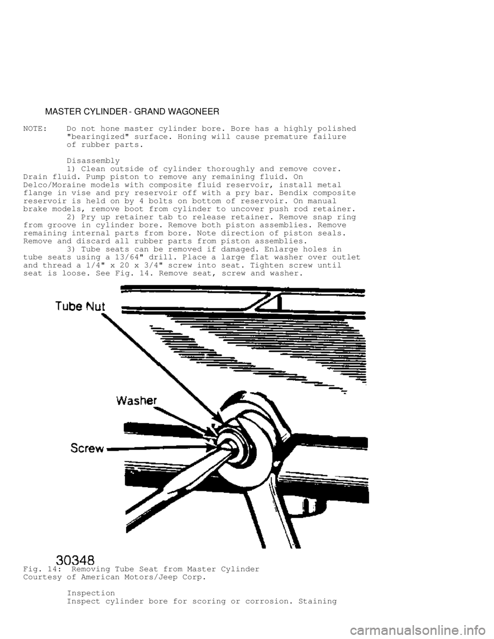
3) Tube seats can be removed if damaged. Enlarge holes in
tube seats using a 13/64" drill. Place a large flat washer over outlet
and thread a 1/4" x 20 x 3/4" screw into seat. Tighten screw until
seat is loose. See Fig. 14. Remove seat, screw and washer.
Fig. 14: Removing Tube Seat from Master Cylinder
Courtesy of American Motors/Jeep Corp.
Inspection
Inspect cylinder bore for scoring or corrosion. Staining
Page 335 of 1378
which has not pitted or roughened surface of cylinder can be removed
with crocus cloth. If cylinder bore is scored, pitted or corroded,
replace master cylinder.
Reassembly
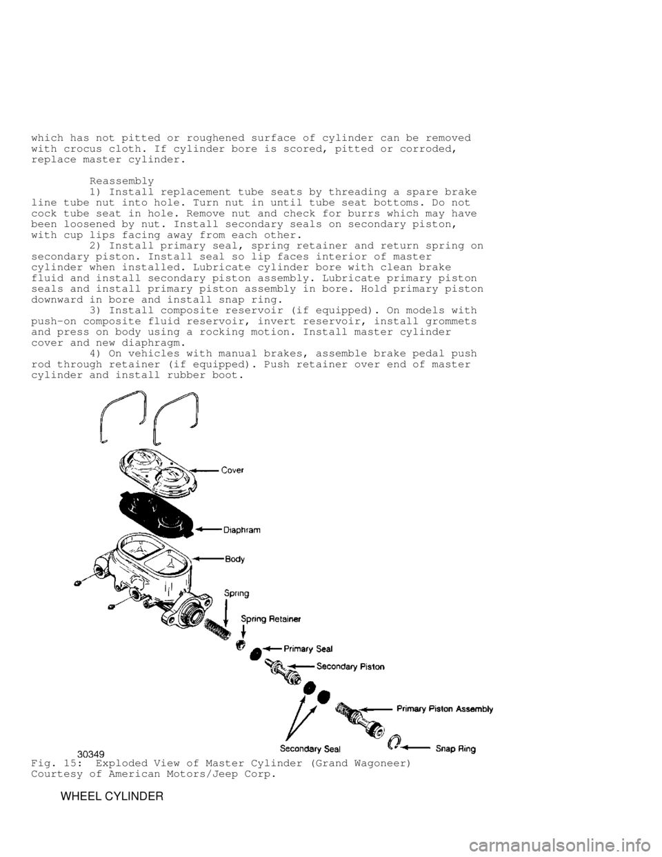
1) Install replacement tube seats by threading a spare brake
line tube nut into hole. Turn nut in until tube seat bottoms. Do not
cock tube seat in hole. Remove nut and check for burrs which may have
been loosened by nut. Install secondary seals on secondary piston,
with cup lips facing away from each other.
2) Install primary seal, spring retainer and return spring on
secondary piston. Install seal so lip faces interior of master
cylinder when installed. Lubricate cylinder bore with clean brake
fluid and install secondary piston assembly. Lubricate primary piston
seals and install primary piston assembly in bore. Hold primary piston
downward in bore and install snap ring.
3) Install composite reservoir (if equipped). On models with\
push-on composite fluid reservoir, invert reservoir, install grommets
and press on body using a rocking motion. Install master cylinder
cover and new diaphragm.
4) On vehicles with manual brakes, assemble brake pedal push
rod through retainer (if equipped). Push retainer over end of master
cylinder and install rubber boot.
Fig. 15: Exploded View of Master Cylinder (Grand Wagoneer)
Courtesy of American Motors/Jeep Corp.
WHEEL CYLINDER
Page 378 of 1378
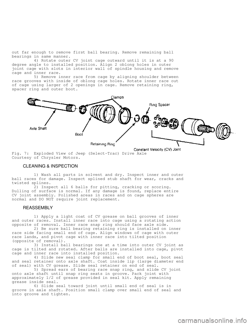
out far enough to remove first ball bearing. Remove remaining ball
bearings in same manner.
4) Rotate outer CV joint cage outward until it is at a 90
degree angle to installed position. Align 2 oblong holes in outer
joint cage with slots in interior wall of spindle housing and remove
cage and inner race.
5) Remove inner race from cage by aligning shoulder between
race grooves with inside of oblong cage holes. Rotate inner race out
of cage using larger of 2 openings in cage. Remove retaining ring,
spacer ring and outer boot.
Fig. 7: Exploded View of Jeep (Select-Trac) Drive Axle
Courtesy of Chrysler Motors.
CLEANING & INSPECTION
1) Wash all parts in solvent and dry. Inspect inner and outer
ball races for damage. Inspect splined stub shaft for wear, cracks and
twisted splines.
2) Inspect all 6 balls for pitting, cracking or scoring.
Dulling of surface is normal. If any damage is found, replace entire
CV joint assembly. Polished areas in races and on cage spheres are
normal and DO NOT require joint replacement.
REASSEMBLY
1) Apply a light coat of CV grease on ball grooves of inner
and outer races. Install inner race into cage using a rotating action
opposite of removal. Inner race snap ring should face axle side.
2) Be sure ball bearing retaining ring is installed on inner
race side facing small end of cage. Align windows of cage with outer
race lands, and pivot cage with inner race into tilted position
(opposite of removal).
3) Install ball bearings one at a time into outer CV joint as
cage is tilted and rotated. After balls are installed into cage, pivot
cage and inner race into installed position.
4) Slide new seal clamp for small end of boot seal, boot seal
and seal retainer onto axle shaft. Coat inside lip (large diameter end
of seal) with CV grease. Slide seal retainer on end of seal.
5) Spread ears of bearing race snap ring, and slide CV joint
onto axle shaft until snap ring seats in groove. Pack joint with
approximately 1/2 of grease provided in seal kit. Apply remaining
grease inside seal.
6) Slide seal toward joint until small end of seal is in
groove in axle shaft. Position small clamp over small end of seal and
into groove and tighten.
Page 386 of 1378

PINION DEPTH
1) Depth Gauge Set (D-271) is used to determine pinion depth\
.
Place Master Pinion Block (D-139 on Model 44; D-120 on Model 60 and
61; D-137 on Model 70; T80T-4020-F42 on Model 80) in pinion bore of
carrier. Put Arbor Discs (D-115-4-44 on Model 44; D-116-2 on Models
60,61 and 70; (T88T-4020-A) on Arbor (D-115-3). Install arbor in
carrier with discs riding in bearing bore.
2) Put Pinion Height Block (D-115-1-44 on Model 44; D-116-1
on Models 60, 61, 70 and 80) on top of master pinion block with side
against arbor. Place Scooter Block (115-2) with Dial Indicator (D-106\
-
5) on small step of pinion height block. Zero dial indicator with
scooter block flat on pinion height block.
3) Move scooter block so dial indicator tip touches arbor.
Move block back and forth (perpendicular to arbor) to get highest
reading. This reading, plus or minus value etched on pinion head, is
thickness of shim pack necessary for pinion bearing.
4) On Model 80, Use Gauge Tube (D81T-4020-F51) and Gauge
Block (D81T-4020-F56) to determine required thickness of shim pack.
5) On all models, measure shims separately with micrometer.
If baffle is used, its thickness must be included in shim pack. This
is also true if slinger is used between inner bearing and head of
pinion shaft. Place pinion height shim pack in carrier bore for inner
bearing race. Drive bearing race into carrier, making sure cup is
fully seated.
PINION BEARING PRELOAD
1) Drive outer pinion bearing into carrier housing. Press
inner pinion bearing onto pinion shaft using Press Tube (C-3095-A).
Ensure bearing seats fully. Insert pinion shaft into carrier. Install
outer bearing, slinger (if equipped), flange, washer and nut.
NOTE: Pinion preload shims and oil seal should NOT be installed at
this time.
2) Using an INCH lb. torque wrench, tighten pinion nut until
10 INCH lbs. (1.13 N.m) rotational torque is required to move pinion
shaft. Recheck pinion depth with arbor and discs at this time. Place
pinion height block on face of pinion shaft.
3) Place dial indicator on small step of height block for
Model 44, 60 and 61 axles. Place dial indicator on high step of block
for Models 70 and 80 axles. Zero dial indicator and move it across
arbor to get highest reading. If reading is within .002" (.05 mm) of
etching on pinion face, pinion depth is correct.
NOTE: If pinion depth is not with .002" (.05 mm) of etched number
on face of pinion, shim pack under inner bearing race must
be changed before proceeding with differential settings.
4) Remove pinion nut, washer, flange, slinger and outer
bearing. Place preload shims (removed during disassembly) on pinion.
Install bearing and slinger. After lightly coating lips with gear oil,
install pinion seal in carrier housing. Install flange, washer and NEW
pinion nut. Tighten nut to specification. See TORQUE SPECIFICATIONS
table at end of this article.
5) Using an INCH lb. torque wrench, measure preload
(rotational torque) of pinion shaft. Rotational torque required to
keep pinion shaft turning freely and smoothly should be 20-40 INCH
lbs. (2.3-4.5 N.m). If preload needs to be increased, remove a few
shims and recheck. To decrease preload, add a few shims and recheck.
See Fig. 14 .
Page 619 of 1378
cylinder head design and type of metal used.
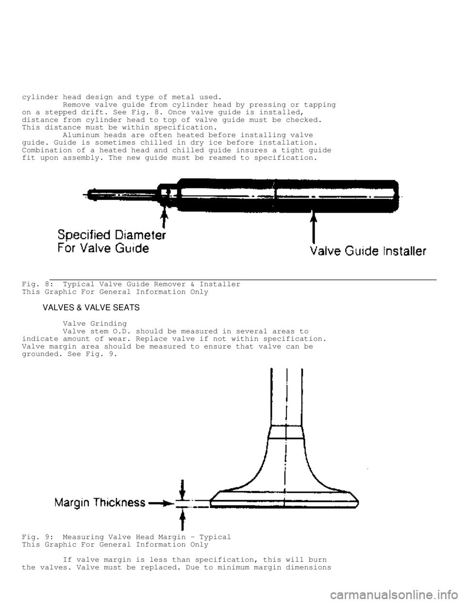
Remove valve guide from cylinder head by pressing or tapping
on a stepped drift. See Fig. 8. Once valve guide is installed,
distance from cylinder head to top of valve guide must be checked.
This distance must be within specification.
Aluminum heads are often heated before installing valve
guide. Guide is sometimes chilled in dry ice before installation.
Combination of a heated head and chilled guide insures a tight guide
fit upon assembly. The new guide must be reamed to specification.
Fig. 8: Typical Valve Guide Remover & Installer
This Graphic For General Information Only
VALVES & VALVE SEATS
Valve Grinding
Valve stem O.D. should be measured in several areas to
indicate amount of wear. Replace valve if not within specification.
Valve margin area should be measured to ensure that valve can be
grounded. See Fig. 9.
Fig. 9: Measuring Valve Head Margin - Typical
This Graphic For General Information Only
If valve margin is less than specification, this will burn
the valves. Valve must be replaced. Due to minimum margin dimensions
Page 620 of 1378
during manufacture, some new type valves cannot be reground.
Resurface valve on proper angle specification using valve
grinding machine. Follow manufacturer's instructions for valve
grinding machine. Specifications may indicate a different valve face
angle than seat angle.
Measure valve margin after grinding. Replace valve if not
within specification. Valve stem tip can be refinished using valve
grinding machine.
Valve Lapping
During valve lapping of recent designed valves, be sure to
follow manufacturers recommendations. Surface hardening and materials
used with some valves do not permit lapping. Lapping process will
remove excessive amounts of the hardened surface.
Valve lapping is done to ensure adequate sealing between
valve face and seat. Use either a hand drill or lapping stick with
suction cup attached.
Moisten and attach suction cup to valve. Lubricate valve stem
and guide. Apply a thin coat of fine valve grinding compound between
valve and seat. Rotate lapping tool between the palms or with hand
drill.
Lift valve upward off the seat and change position often.
This is done to prevent grooving of valve seat. Lap valve until a
smooth polished seat is obtained. Thoroughly clean grinding compound
from components. Valve to valve seat concentricity should be checked.
See VALVE SEAT CONCENTRICITY.
CAUTION: Valve guides must be in good condition and free of carbon
deposits prior to valve seat grinding. Some engines contain
an induction hardened valve seat. Excessive material removal
will damage valve seats.
Valve Seat Grinding
Select coarse stone of correct size and angle for seat to be
ground. Ensure stone is true and has a smooth surface. Select correct
size pilot for valve guide dimension. Install pilot in valve guide.
Lightly lubricate pilot shaft. Install stone on pilot. Move stone off
and on the seat approximately 2 times per second during grinding
operation.
Select a fine stone to finish grinding operation. Grinding
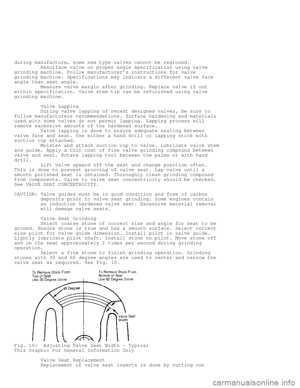
stones with 30 and 60 degree angles are used to center and narrow the
valve seat as required. See Fig. 10.
Fig. 10: Adjusting Valve Seat Width - Typical
This Graphic For General Information Only
Valve Seat Replacement
Replacement of valve seat inserts is done by cutting out
Page 621 of 1378
the old insert and machining an oversize insert bore. Replacement
oversize insert is usually chilled and the cylinder head is sometimes
warmed. Valve seat is pressed into the head. This operation requires
specialized machine shop equipment.
Valve Seat Concentricity
Using dial gauge, install gauge pilot in valve guide.
Position gauge arm on the valve seat. Adjust dial indicator to zero.
Rotate arm 360 degrees and note reading. Runout should not exceed
specification.
To check valve-to-valve seat concentricity, coat valve face
lightly with Prussian Blue dye. Install valve and rotate it on valve
seat. If pattern is even and entire seat is coated at valve contact
point, valve is concentric with the seat.
REASSEMBLY
Valve Stem Installed Height
Valve stem installed height must be checked when new valves
are installed or when valves or valve seats have been ground. Install
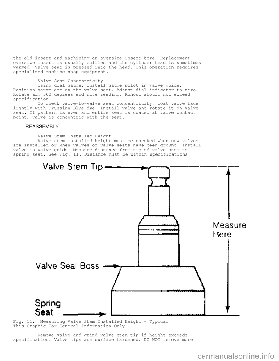
valve in valve guide. Measure distance from tip of valve stem to
spring seat. See Fig. 11. Distance must be within specifications.
Fig. 11: Measuring Valve Stem Installed Height - Typical
This Graphic For General Information Only
Remove valve and grind valve stem tip if height exceeds
specification. Valve tips are surface hardened. DO NOT remove more
Page 622 of 1378
than .010" (.25 mm) from tip. Chamfer sharp edge of reground valve
tip. Recheck valve stem installed height.
VALVE STEM OIL SEALS
Valve stem oil seals must be installed on valve stem. See
Fig. 2 . Seals are needed due to pressure differential at the ends of
valve guides. Atmospheric pressure above intake guide, combined with
manifold vacuum below guide, causes oil to be drawn into the cylinder.
Exhaust guides also have pressure differential created by
exhaust gas flowing past the guide, creating a low pressure area. This
low pressure area draws oil into the exhaust system.
Replacement (On Vehicle)
Mark rocker arm or overhead cam components for location.
Remove rocker arm components or overhead cam components. Components
must be installed in original location. Remove spark plugs. Valve stem
oil seals may be replaced by holding valves against seats using air
pressure.
Air pressure must be installed in cylinder using an adapter
for spark plug hole. An adapter can be constructed by welding air hose
connection to spark plug body with porcelain removed.
Install adapter in spark plug hole. Apply a minimum of 140
psi (9.8 kg/cm
�) to adapter. Air pressure should hold valve closed. If
air pressure does not hold valve closed, check for damaged or bent
valve. Cylinder head must be removed for service.
Using valve spring compressor, compress valve springs. Remove
valve locks. Carefully release spring compressor. Remove retainer or
rotator and valve spring. Remove valve stem oil seal.
If oversized valves have been installed, oversized oil seals
must be used. Coat valve stem with engine oil. Install protective
sleeve over end of valve stem. Install new oil seal over valve stem
and seat on valve guide. Remove protective sleeve. Install spring
seat, valve spring and retainer or rotator. Compress spring and
install valve locks. Remove spring compressor. Ensure valve locks
are fully seated.
Install rocker arms or overhead cam components. Tighten all
bolts to specification. Adjust valves if required. Remove adapter.
Install spark plugs, valve cover and gasket.
VALVE SPRING INSTALLED HEIGHT
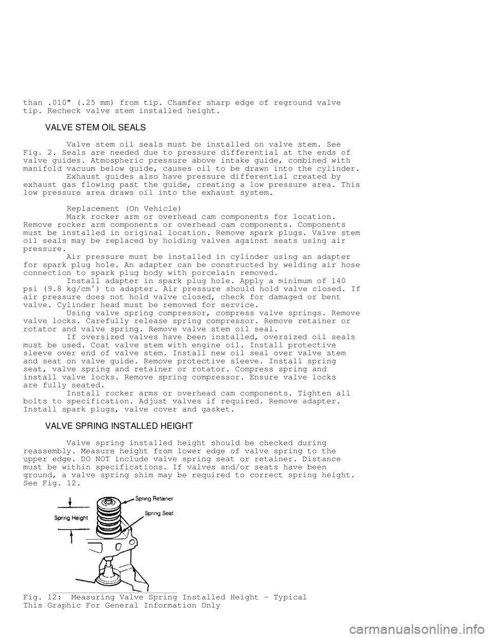
Valve spring installed height should be checked during
reassembly. Measure height from lower edge of valve spring to the
upper edge. DO NOT include valve spring seat or retainer. Distance
must be within specifications. If valves and/or seats have been
ground, a valve spring shim may be required to correct spring height.
See Fig. 12 .
Fig. 12: Measuring Valve Spring Installed Height - Typical
This Graphic For General Information Only
Page 829 of 1378

1 - 25 Amp
Rear Washer/Wiper.
2 - 15 Amp
Radio, Cigarette Lighter.
3 - 25 Amp
Blower Motor.
4 - 20 Amp
Turn Signal, Back-Up Lights, Rear Window Defogger Relay.
5 - 10 Amp
Dome Light, Courtesy Lights, Glove Box Light, Cargo Light,
Radio Memory, Power Mirrors, Teltak Connector.
6 - 15 Amp
Hazard Warning System, Stoplights.
7 - 10 Amp
Parking Lights, Headlight Warning Chime/Buzzer, Instrument
Panel Light Dimmer.
8 - 7.5 Amp
Gauges, Instrument Cluster, Seat Belt Warning, Headlight
Delay, Chime Module, Overhead Console.
9 - 5 Amp
Instrument Panel Illumination.
10 - 25 Amp
Rear Window Defogger.
11 - 30 Amp (Circuit Breaker)
Power Door Locks, Power Seats, Trailer Towing Wiring Harness.
12 - 10 Amp
ETR Radio, Power Antenna.
13 - Not Used (1984-87); 7.5 Amp (1988)
Transmission Control Unit.
14 - 25 Amp
Headlight Delay, Horns, Security Alarm.
15 - 5.5 Amp (Circuit Breaker)
Front Wiper.
16 - 30 Amp (Circuit Breaker)
Power Windows.
17 - 10 Amp
Clock, Security Alarm (Ign).
CAUTIONS & WARNINGS
REPLACING BLOWN FUSES
Before replacing a blown fuse, remove ignition key, turn off
all lights and accessories to avoid damaging the electrical system. Be
sure to use fuse with the correct indicated amperage rating. The use
of an incorrect amperage rating fuse may result in a dangerous