wiring JEEP CHEROKEE 1994 Service User Guide
[x] Cancel search | Manufacturer: JEEP, Model Year: 1994, Model line: CHEROKEE, Model: JEEP CHEROKEE 1994Pages: 1784, PDF Size: 77.09 MB
Page 247 of 1784
CAUTION: Do not operate an engine without a ther-
mostat, except for servicing or testing.
ON-BOARD DIAGNOSTICS
XJ and YJ models are equipped with On-Board Di-
agnostics for certain cooling system components. Re-
fer to On-Board Diagnostics (OBD) in the Diagnosis
section of this group for additional information. If the
powertrain control module (PCM) detects low engine
coolant temperature, it will record a Diagnostic Trou-
ble Code (DTC) in the PCM memory. The DTC num-
ber for low coolant temperature is 17. Do not change
a thermostat for lack of heat as indicated by the in-
strument panel gauge or heater performance unless a
DTC number 17 is present. Refer to the Diagnosis
section of this group for other probable causes. For
other DTC numbers, refer to On-Board Diagnostics
in the General Diagnosis section of group 14, Fuel
Systems.
The DTC can also be accessed through the DRB
scan tool. Refer to the appropriate Powertrain Diag-
nostic Procedures manual for diagnostic information
and operation of the DRB scan tool.
REMOVAL
WARNING: DO NOT LOOSEN THE RADIATOR
DRAINCOCK WITH THE SYSTEM HOT AND PRES-
SURIZED. SERIOUS BURNS FROM THE COOLANT
CAN OCCUR.
DO NOT WASTE reusable coolant. If the solution
is clean, drain the coolant into a clean container for
reuse.
(1) Drain the coolant from the radiator until the
level is below the thermostat housing.
WARNING: CONSTANT TENSION HOSE CLAMPS
ARE USED ON MOST COOLING SYSTEM HOSES.
WHEN REMOVING OR INSTALLING, USE ONLY
TOOLS DESIGNED FOR SERVICING THIS TYPE OF
CLAMP, SUCH AS SPECIAL CLAMP TOOL (NUM-
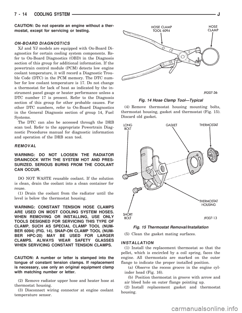
BER 6094) (FIG. 14). SNAP-ON CLAMP TOOL (NUM-
BER HPC-20) MAY BE USED FOR LARGER
CLAMPS. ALWAYS WEAR SAFETY GLASSES
WHEN SERVICING CONSTANT TENSION CLAMPS.
CAUTION: A number or letter is stamped into the
tongue of constant tension clamps. If replacement
is necessary, use only an original equipment clamp
with matching number or letter.
(2) Remove radiator upper hose and heater hose at
thermostat housing.
(3) Disconnect wiring connector at engine coolant
temperature sensor.(4) Remove thermostat housing mounting bolts,
thermostat housing, gasket and thermostat (Fig. 15).
Discard old gasket.
(5) Clean the gasket mating surfaces.
INSTALLATION
(1) Install the replacement thermostat so that the
pellet, which is encircled by a coil spring, faces the
engine. All thermostats are marked on the outer
flange to indicate the proper installed position.
(a) Observe the recess groove in the engine cyl-
inder head (Fig. 16).
(b) Position thermostat in groove with arrow and
air bleed hole on outer flange pointing up.
(2) Install replacement gasket and thermostat
housing.
Fig. 14 Hose Clamp ToolÐTypical
Fig. 15 Thermostat Removal/Installation
7 - 14 COOLING SYSTEMJ
Page 274 of 1784
ELECTRICAL
GROUP INDEX
Group Group
AUDIO SYSTEMS....................... 8F
BATTERY/STARTER/GENERATOR SERVICE . . 8B
BATTERY/STARTING/CHARGING SYSTEMS
DIAGNOSTICS........................ 8A
CHIME/WARNING BUZZER SYSTEM....... 8U
HORNS............................... 8G
IGNITION SYSTEMS.................... 8D
INSTRUMENT PANEL AND GAUGES........ 8E
LAMPS............................... 8L
OVERHEAD CONSOLE................... 8CPOWER LOCKS........................ 8P
POWER MIRRORS...................... 8T
POWER SEAT.......................... 8R
POWER WINDOWS..................... 8S
REAR WINDOW DEFOGGER.............. 8N
TURN SIGNALS AND HAZARD WARNING
FLASHERS........................... 8J
VEHICLE SPEED CONTROL SYSTEM....... 8H
WINDSHIELD WIPERS AND WASHERS..... 8K
WIRING DIAGRAMS.................... 8W
BATTERY/STARTING/CHARGING SYSTEMS DIAGNOSTICS
CONTENTS
page page
BATTERY TEST PROCEDURES............. 2
ENGINE STARTER MOTOR TEST
PROCEDURES ON VEHICLE.............. 9GENERATOR TEST PROCEDURES ON
VEHICLE............................. 14
IGNITION OFF DRAW (IOD) DIAGNOSIS...... 8
USING ON-BOARD DIAGNOSTIC SYSTEM.... 19
GENERAL INFORMATION
The battery, starting, and charging systems oper-
ate with one another, and therefore, must be thor-
oughly tested as a complete system. In order for the
vehicle to start and charge properly, it must have a
battery that will perform to specifications. The
starter motor, generator, wiring, and electronics also
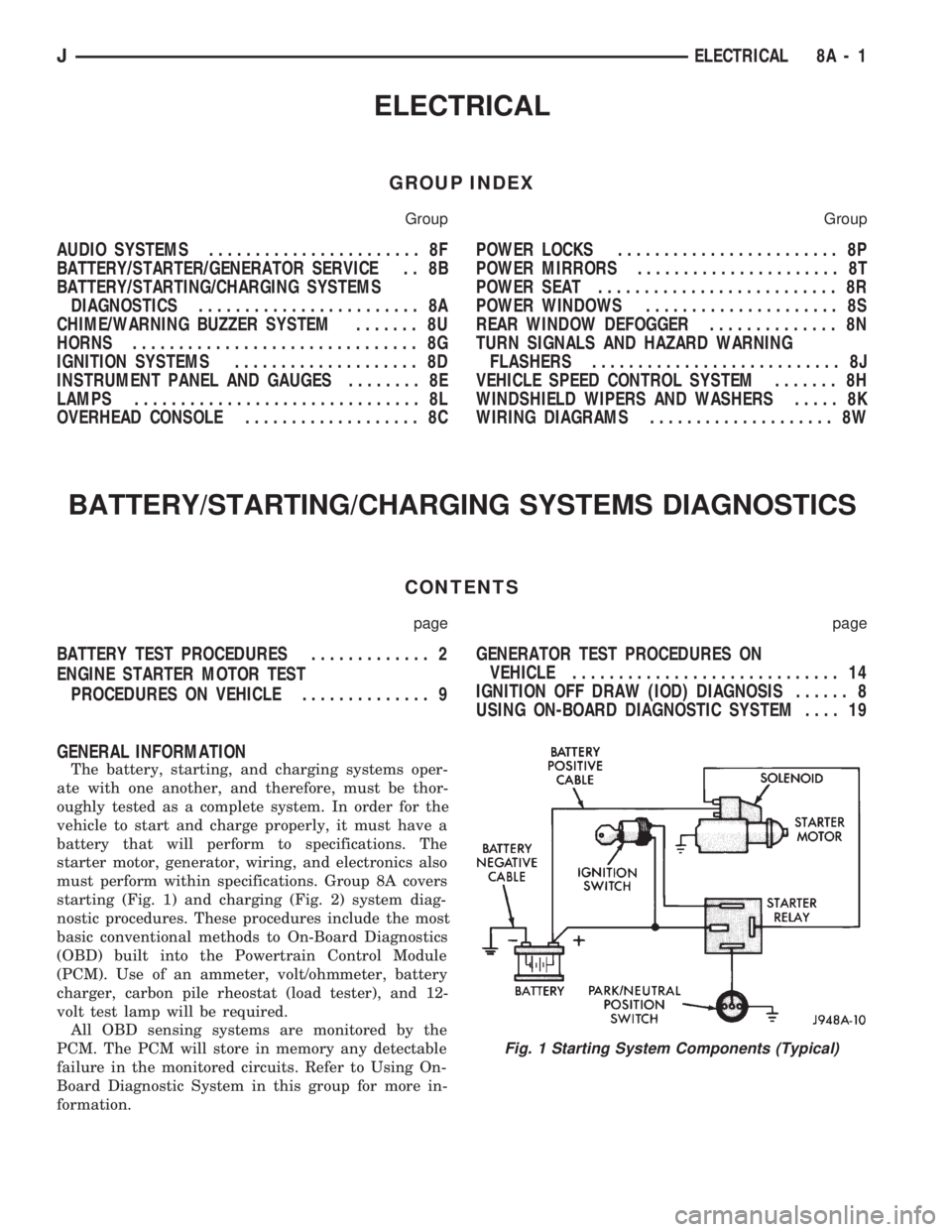
must perform within specifications. Group 8A covers
starting (Fig. 1) and charging (Fig. 2) system diag-
nostic procedures. These procedures include the most
basic conventional methods to On-Board Diagnostics
(OBD) built into the Powertrain Control Module
(PCM). Use of an ammeter, volt/ohmmeter, battery
charger, carbon pile rheostat (load tester), and 12-
volt test lamp will be required.
All OBD sensing systems are monitored by the
PCM. The PCM will store in memory any detectable
failure in the monitored circuits. Refer to Using On-
Board Diagnostic System in this group for more in-
formation.
Fig. 1 Starting System Components (Typical)
JELECTRICAL 8A - 1
Page 281 of 1784
SPECIFICATIONS
IGNITION OFF DRAW (IOD) DIAGNOSIS
GENERAL INFORMATION
Ignition off draw refers to power being drained
from the battery with the ignition switch turned off.
A normal vehicle electrical system will draw from 5
to 20 milliamps. This is with the ignition switch in
the OFF position, and all non-ignition controlled cir-
cuits in proper working order. A vehicle that has not
been operated for approximately 20 days, may dis-
charge the battery to an inadequate level. Battery
drain should not exceed approximately 20 MA (20
milliamps = 0.020 amps).
The 20 MA are needed to supply PCM memory,
digital clock memory, and ETR (electronically tuned
radio) memory.
Excessive battery drain is caused by items left
turned on, internally shorted generator, or intermit-
tent short in wiring.
If the IOD is over 20 milliamperes, the defect must
be found and corrected before replacing a battery. In
most cases the battery can be charged and returned
to service.
When a vehicle will not be used for 20 days or
more (stored), remove IOD fuse in the Power Distri-
bution Center to reduce battery discharging.
TEST PROCEDURE
Testing for higher amperage IOD must be per-
formed first to prevent damage to most milliamp
meters.
(1) Verify that all electrical accessories are OFF.
Turn off all lamps, remove ignition key, and close all
doors. If the vehicle is equipped with electronic acces-
sories (illuminated entry, high line radio), allow the
systems to automatically shut off (time out), up to 3
minutes.
(2) Determine that the underhood lamp is operat-
ing properly, then disconnect or remove bulb.
(3) Disconnect negative cable from battery.
(4) Connect a typical 12-volt test lamp (low watt-
age bulb) between the negative cable clamp and the
battery negative terminal. If equipped with security
alarm, cycle the key in the door to turn off the flash-ing lights. Make sure that the doors remain closed so
that illuminated entry is not activated.
The test lamp may light brightly for up to 3 min-
utes or may not light at all (depending on the elec-
trical equipment). The term brightly being used
throughout the following tests, implies the bright-
ness of the test lamp will be the same as if it were
connected across the battery.
The test lamp must be securely clamped to the neg-
ative cable and battery terminal. If the test lamp be-
comes disconnected during any part of the IOD test,
the electronic timer function will be activated and all
tests must be repeated.
If the ammeter circuit is broken the Security
Alarm Module will turn on parking lamps.
(5) After 3 minutes, the test lamp should turn OFF
or be DIMLY lit (depending on the electrical equip-
ment). If the test lamp remains brightly lit do not
disconnect it. Remove each fuse or circuit breaker
(refer to Group 8 - Wiring Diagrams) until test lamp
is either OFF or DIMLY lit. This will eliminate the
higher amperage draw.
If test lamp is still bright after disconnecting each
fuse and circuit breaker, disconnect the wiring har-
ness from the generator. Refer to Generator Test Pro-
cedures in this group. Do not disconnect the test
lamp.
After higher amperage IOD has been corrected, low
amperage IOD may be checked.
It is now safe to install milliamp meter to check for
low amperage IOD.
(6) With test lamp still connected securely, clamp
an ammeter between battery negative terminal and
negative battery cable.
Do not open any doors or turn on any electri-
cal accessories with the test lamp disconnected
or the meter may be damaged.
(7) Disconnect test lamp. The current draw should
not exceed 0.020 amp. If it exceeds 0.020 milliamps,
isolate each circuit by removing circuit breakers and
fuses. The meter reading drops once the high current
problem is found. Repair this section of the circuit,
whether it is a wiring short or component failure.
BATTERY CLASSIFICATIONS AND RATINGSTORQUE SPECIFICATIONS
8A - 8 BATTERY/STARTING/CHARGING SYSTEMS DIAGNOSTICSJ
Page 282 of 1784
ENGINE STARTER MOTOR TEST PROCEDURES ON VEHICLE
INDEX
page page
2.5L Starter Motor Noise Diagnosis........... 13
General Information........................ 9
Starter Control Circuit Tests................ 11
Starter Feed Circuit Tests - (Voltage Drop Method).9
Starter System Diagnostic Inspections.......... 9
Starting System Cold Cranking Test........... 9
GENERAL INFORMATION
The starting system consists of an:
²ignition switch
²starter relay
²park/neutral position switch (automatic transmis-
sion)
²wiring harness
²battery
²starter motor with an integral solenoid.
These components form 2 separate circuits. A high
amperage circuit that feeds the starter motor up to
300+ amps, and a control circuit that operates on
less than 20 amps.
STARTER SYSTEM DIAGNOSTIC INSPECTIONS
Before removing any unit from the starter motor
system for repair, perform the following inspections:
BATTERY INSPECTION
To determine condition of the battery, perform the
testing procedure outlined in Battery Test Proce-
dures.
WIRING INSPECTION
Inspect wiring for damage. Inspect all connections
at the starter motor solenoid, park/neutral position
switch (if equipped), back-up lamp switch connector,
ignition switch, starter relay, and battery (including
all ground connections). Clean and tighten all con-
nections as required.
SOLENOID, RELAY AND IGNITION SWITCH
INSPECTION
Inspect the solenoid, relay and switch to determine
their condition. Also, if equipped with automatic
transmission, inspect condition of the park/neutral
position switch. Testing information can be found in
the following pages.
STARTING SYSTEM COLD CRANKING TEST
(1) Battery must first pass load and voltage drop
tests and be fully charged before proceeding. Refer to
Battery Test Procedures.(2) Connect a suitable volt-ampere tester to the
battery terminals (Fig. 1). Refer to the operating in-
structions provided with the tester being used.
(3) Fully engage parking brake, place manual
transmission in NEUTRAL, automatic transmission
in PARK.
(4) Verify that all lamps and accessories are OFF.
(5) Remove coil secondary cable from distributor
and connect to ground.
(6) Rotate and hold the ignition switch in the
START position. Note cranking voltage and amper-
age.
(a) If voltage reads above 9.6 volts and amperage
draw reads above specifications, go to Starter Feed
Circuit Tests.
(b) If voltage reads 12.5 volts or greater and am-
perage reads below specifications, go to Starter
Control Circuit Tests.
A cold engine will increase starter motor cur-
rent and reduce battery voltage.
STARTER FEED CIRCUIT TESTS - (VOLTAGE DROP
METHOD)
The voltage drop tests will determine if there is ex-
cessive resistance in the high current circuit. When
performing these tests, it is important that the volt-
meter be connected to the terminals that the cables
are connected to, instead of to the cables themselves.
For example, when testing between the battery and
solenoid, touch the voltmeter test probes to the bat-
tery post and the solenoid threaded stud. The follow-
ing operation will require a voltmeter, accurate to
1/10 of a volt.
Before performing the tests, assure the following
procedures are accomplished:
²remove coil secondary cable from distributor and
connect to ground
²transmission in NEUTRAL (manual transmission)
or PARK (automatic transmission)
²parking brake applied
²battery is fully charged (refer to Battery Test Pro-
cedures).
JBATTERY/STARTING/CHARGING SYSTEMS DIAGNOSTICS 8A - 9
Page 284 of 1784
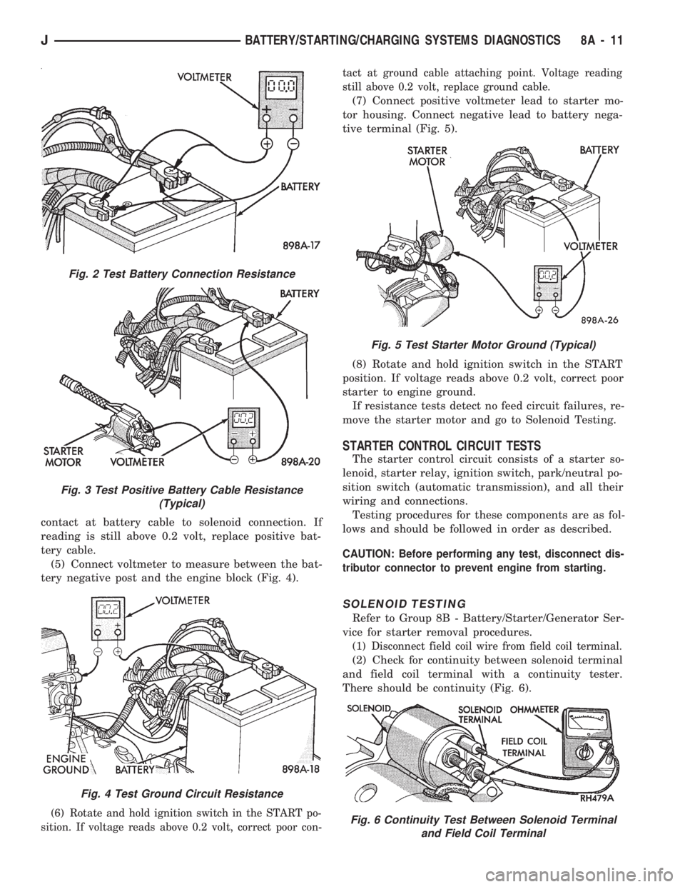
contact at battery cable to solenoid connection. If
reading is still above 0.2 volt, replace positive bat-
tery cable.
(5) Connect voltmeter to measure between the bat-
tery negative post and the engine block (Fig. 4).
(6) Rotate and hold ignition switch in the START po-
sition. If voltage reads above 0.2 volt, correct poor con-tact at ground cable attaching point. Voltage reading
still above 0.2 volt, replace ground cable.
(7) Connect positive voltmeter lead to starter mo-
tor housing. Connect negative lead to battery nega-
tive terminal (Fig. 5).
(8) Rotate and hold ignition switch in the START
position. If voltage reads above 0.2 volt, correct poor
starter to engine ground.
If resistance tests detect no feed circuit failures, re-
move the starter motor and go to Solenoid Testing.
STARTER CONTROL CIRCUIT TESTS
The starter control circuit consists of a starter so-
lenoid, starter relay, ignition switch, park/neutral po-
sition switch (automatic transmission), and all their
wiring and connections.
Testing procedures for these components are as fol-
lows and should be followed in order as described.
CAUTION: Before performing any test, disconnect dis-
tributor connector to prevent engine from starting.
SOLENOID TESTING
Refer to Group 8B - Battery/Starter/Generator Ser-
vice for starter removal procedures.
(1) Disconnect field coil wire from field coil terminal.
(2) Check for continuity between solenoid terminal
and field coil terminal with a continuity tester.
There should be continuity (Fig. 6).
Fig. 2 Test Battery Connection Resistance
Fig. 3 Test Positive Battery Cable Resistance
(Typical)
Fig. 4 Test Ground Circuit Resistance
Fig. 5 Test Starter Motor Ground (Typical)
Fig. 6 Continuity Test Between Solenoid Terminal
and Field Coil Terminal
JBATTERY/STARTING/CHARGING SYSTEMS DIAGNOSTICS 8A - 11
Page 286 of 1784
IGNITION SWITCH TEST
After testing starter solenoid and relay and they
check out OK, trouble is probably with ignition
switch or its wiring.
Check all wiring for opens and shorts, and connec-
tions for being loose or corroded.
PARK/NEUTRAL POSITION SWITCH
Refer to Group 21 - Transmissions for diagnostic
information.
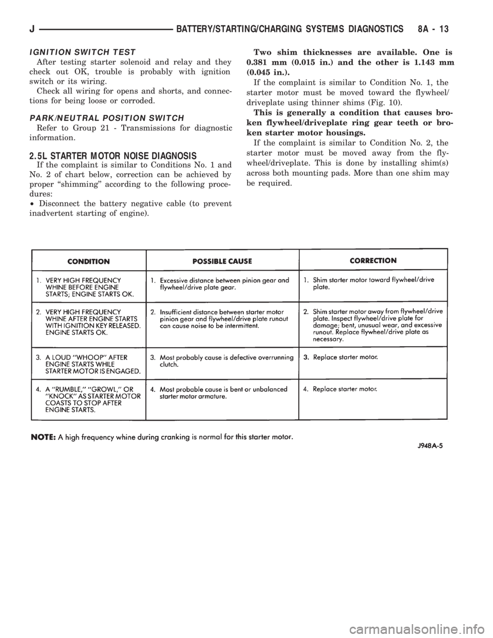
2.5L STARTER MOTOR NOISE DIAGNOSIS
If the complaint is similar to Conditions No. 1 and
No. 2 of chart below, correction can be achieved by
proper ``shimming'' according to the following proce-
dures:
²Disconnect the battery negative cable (to prevent
inadvertent starting of engine).Two shim thicknesses are available. One is
0.381 mm (0.015 in.) and the other is 1.143 mm
(0.045 in.).
If the complaint is similar to Condition No. 1, the
starter motor must be moved toward the flywheel/
driveplate using thinner shims (Fig. 10).
This is generally a condition that causes bro-
ken flywheel/driveplate ring gear teeth or bro-
ken starter motor housings.
If the complaint is similar to Condition No. 2, the
starter motor must be moved away from the fly-
wheel/driveplate. This is done by installing shim(s)
across both mounting pads. More than one shim may
be required.
JBATTERY/STARTING/CHARGING SYSTEMS DIAGNOSTICS 8A - 13
Page 289 of 1784
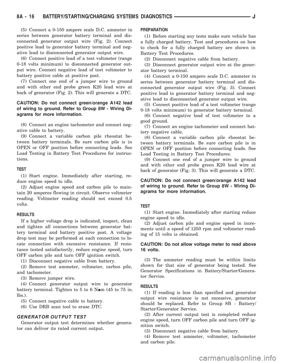
(5) Connect a 0-150 ampere scale D.C. ammeter in
series between generator battery terminal and dis-
connected generator output wire (Fig. 2). Connect
positive lead to generator battery terminal and neg-
ative lead to disconnected generator output wire.
(6) Connect positive lead of a test voltmeter (range
0-18 volts minimum) to disconnected generator out-
put wire. Connect negative lead of test voltmeter to
battery positive cable at positive post.
(7) Connect one end of a jumper wire to ground
and with other end probe green K20 lead wire at
back of generator (Fig. 2). This will generate a DTC.
CAUTION: Do not connect green/orange A142 lead
of wiring to ground. Refer to Group 8W - Wiring Di-
agrams for more information.
(8) Connect an engine tachometer and connect neg-
ative cable to battery.
(9) Connect a variable carbon pile rheostat be-
tween battery terminals. Be sure carbon pile is in
OPEN or OFF position before connecting leads. See
Load Testing in Battery Test Procedures for instruc-
tions.
TEST
(1) Start engine. Immediately after starting, re-
duce engine speed to idle.
(2) Adjust engine speed and carbon pile to main-
tain 20 amperes flowing in circuit. Observe voltmeter
reading. Voltmeter reading should not exceed 0.5
volts.
RESULTS
If a higher voltage drop is indicated, inspect, clean
and tighten all connections between generator bat-
tery terminal and battery positive post. A voltage
drop test may be performed at each connection to lo-
cate connection with excessive resistance. If resis-
tance tested satisfactorily, reduce engine speed, turn
OFF carbon pile and turn OFF ignition switch.
(1) Disconnect negative cable from battery.
(2) Remove test ammeter, voltmeter, carbon pile,
and tachometer.
(3) Remove jumper wire.
(4) Connect generator output wire to generator
battery terminal. Tighten to 5 to 6 NIm (45 to 75 in.
lbs.).
(5) Connect negative cable to battery.
(6) Use DRB scan tool to erase DTC.
GENERATOR OUTPUT TEST
Generator output test determines whether genera-
tor can deliver its rated current output.PREPARATION
(1) Before starting any tests make sure vehicle has
a fully charged battery. Test and procedures on how
to check for a fully charged battery are shown in
Battery Test Procedures.
(2) Disconnect negative cable from battery.
(3) Disconnect generator output wire at the gener-
ator battery terminal.
(4) Connect a 0-150 ampere scale D.C. ammeter in
series between generator battery terminal and dis-
connected generator output wire (Fig. 3). Connect
positive lead to generator battery terminal and neg-
ative lead to disconnected generator output wire.
(5) Connect positive lead of a test voltmeter (range
0-18 volts minimum) to generator battery terminal.
(6) Connect negative lead of test voltmeter to a
good ground.
(7) Connect an engine tachometer and connect bat-
tery negative cable.
(8) Connect a variable carbon pile rheostat be-
tween battery terminals. Be sure carbon pile is in
OPEN or OFF position before connecting leads. See
Load Testing in Battery Test Procedures.
(9) Connect one end of a jumper wire to ground
and with other end probe green K20 lead wire at
back of generator (Fig. 3). This will generate a DTC.
CAUTION: Do not connect green/orange A142 lead
of wiring to ground. Refer to Group 8W - Wiring Di-
agrams for more information.
TEST
(1) Start engine. Immediately after starting reduce
engine speed to idle.
(2) Adjust carbon pile and engine speed in incre-
ments until a speed of 1250 rpm and voltmeter read-
ing of 15 volts is obtained.
CAUTION: Do not allow voltage meter to read above
16 volts.
(3) The ammeter reading must be within limits
shown for that size of generator being tested. See
Generator Specifications in Battery/Starter/Genera-
tor Service.
RESULTS
(1) If reading is less than specified and generator
output wire resistance is not excessive, generator
should be replaced. Refer to Group 8B - Battery/
Starter/Generator Service.
(2) After current output test is completed reduce
engine speed, turn OFF carbon pile and turn OFF ig-
nition switch.
(3) Disconnect negative cable from battery.
(4) Remove test ammeter, voltmeter, tachometer
and carbon pile.
8A - 16 BATTERY/STARTING/CHARGING SYSTEMS DIAGNOSTICSJ
Page 311 of 1784
(6) Should any segment in any of the digit positions
fail to light, the unit is defective and should be re-
placed.
THERMOMETER AND SENSOR SYSTEM REPAIR
PROCEDURES
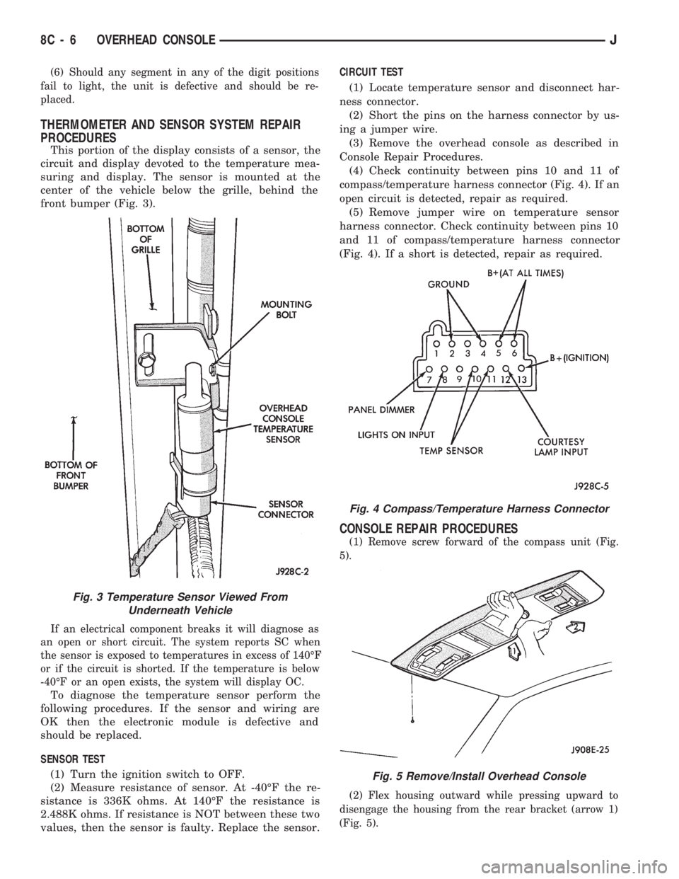
This portion of the display consists of a sensor, the
circuit and display devoted to the temperature mea-
suring and display. The sensor is mounted at the
center of the vehicle below the grille, behind the
front bumper (Fig. 3).
If an electrical component breaks it will diagnose as
an open or short circuit. The system reports SC when
the sensor is exposed to temperatures in excess of 140ÉF
or if the circuit is shorted. If the temperature is below
-40ÉF or an open exists, the system will display OC.
To diagnose the temperature sensor perform the
following procedures. If the sensor and wiring are
OK then the electronic module is defective and
should be replaced.
SENSOR TEST
(1) Turn the ignition switch to OFF.
(2) Measure resistance of sensor. At -40ÉF the re-
sistance is 336K ohms. At 140ÉF the resistance is
2.488K ohms. If resistance is NOT between these two
values, then the sensor is faulty. Replace the sensor.CIRCUIT TEST
(1) Locate temperature sensor and disconnect har-
ness connector.
(2) Short the pins on the harness connector by us-
ing a jumper wire.
(3) Remove the overhead console as described in
Console Repair Procedures.
(4) Check continuity between pins 10 and 11 of
compass/temperature harness connector (Fig. 4). If an
open circuit is detected, repair as required.
(5) Remove jumper wire on temperature sensor
harness connector. Check continuity between pins 10
and 11 of compass/temperature harness connector
(Fig. 4). If a short is detected, repair as required.
CONSOLE REPAIR PROCEDURES
(1) Remove screw forward of the compass unit (Fig.
5).
(2) Flex housing outward while pressing upward to
disengage the housing from the rear bracket (arrow 1)
(Fig. 5).
Fig. 4 Compass/Temperature Harness Connector
Fig. 5 Remove/Install Overhead Console
Fig. 3 Temperature Sensor Viewed From
Underneath Vehicle
8C - 6 OVERHEAD CONSOLEJ
Page 321 of 1784
DIAGNOSTICS/SERVICE PROCEDURES
INDEX
page page
Automatic Shut Down (ASD) Relay............ 8
Camshaft Position Sensor Test............... 8
Crankshaft Position Sensor Test.............. 9
Distributor Cap........................... 9
Distributor Rotor......................... 10
DRB Scan Tool.......................... 10
Engine Coolant Temperature Sensor Test...... 12
General Information........................ 8
Ignition Coil............................. 11
Ignition Secondary Circuit Diagnosis.......... 12Ignition Timing........................... 14
Intake Manifold Air Temperature Sensor Test . . . 14
Manifold Absolute Pressure (MAP) Sensor Test . 14
On-Board Diagnostics (OBD)................ 19
Oxygen Sensor Tests..................... 19
Powertrain Control Module (PCM)............ 15
Spark Plug Secondary Cables............... 17
Spark Plugs............................ 16
Throttle Position Sensor Test............... 18
GENERAL INFORMATION
This section of the group, Diagnostics/Service Pro-
cedures, will discuss basic ignition system diagnos-
tics and service adjustments.
For system operation and component identification,
refer to the Component Identification/System Opera-
tion section of this group.
For removal or installation of ignition system com-
ponents, refer to the Component Removal/Installa-
tion section of this group.
For other useful information, refer to On-Board Di-
agnostics in the General Diagnosis sections of Group
14, Fuel System in this manual.
For operation of the DRB Scan Tool, refer to the
appropriate Powertrain Diagnostic Procedures ser-
vice manual.
AUTOMATIC SHUT DOWN (ASD) RELAY
Refer to RelaysÐOperation/Testing in the Group
14, Fuel System section of this service manual.
CAMSHAFT POSITION SENSOR TEST
The camshaft position sensor is located in the dis-
tributor on all engines.
To perform a complete test of this sensor and its
circuitry, refer to the DRB scan tool. Also refer to the
appropriate Powertrain Diagnostics Procedures man-
ual. To test the sensor only, refer to the following:
2.5L OR 4.0L ENGINE
For this test, an analog voltmeter is needed.Do
not remove the distributor connector from the dis-
tributor. Using small paper clips, insert them into
the backside of the distributor wire harness connec-
tor to make contact with the terminals. Be sure that
the connector is not damaged when inserting the pa-
per clips. Attach voltmeter leads to these paper clips.
(1) Connect the positive (+) voltmeter lead into
the sensor output wire. This is at done the distribu-
tor wire harness connector. For wire identification,
refer to Group 8W, Wiring Diagrams.(2) Connect the negative (-) voltmeter lead into the
ground wire. For wire identification, refer to Group
8W, Wiring Diagrams.
(3) Set the voltmeter to the 15 Volt DC scale.
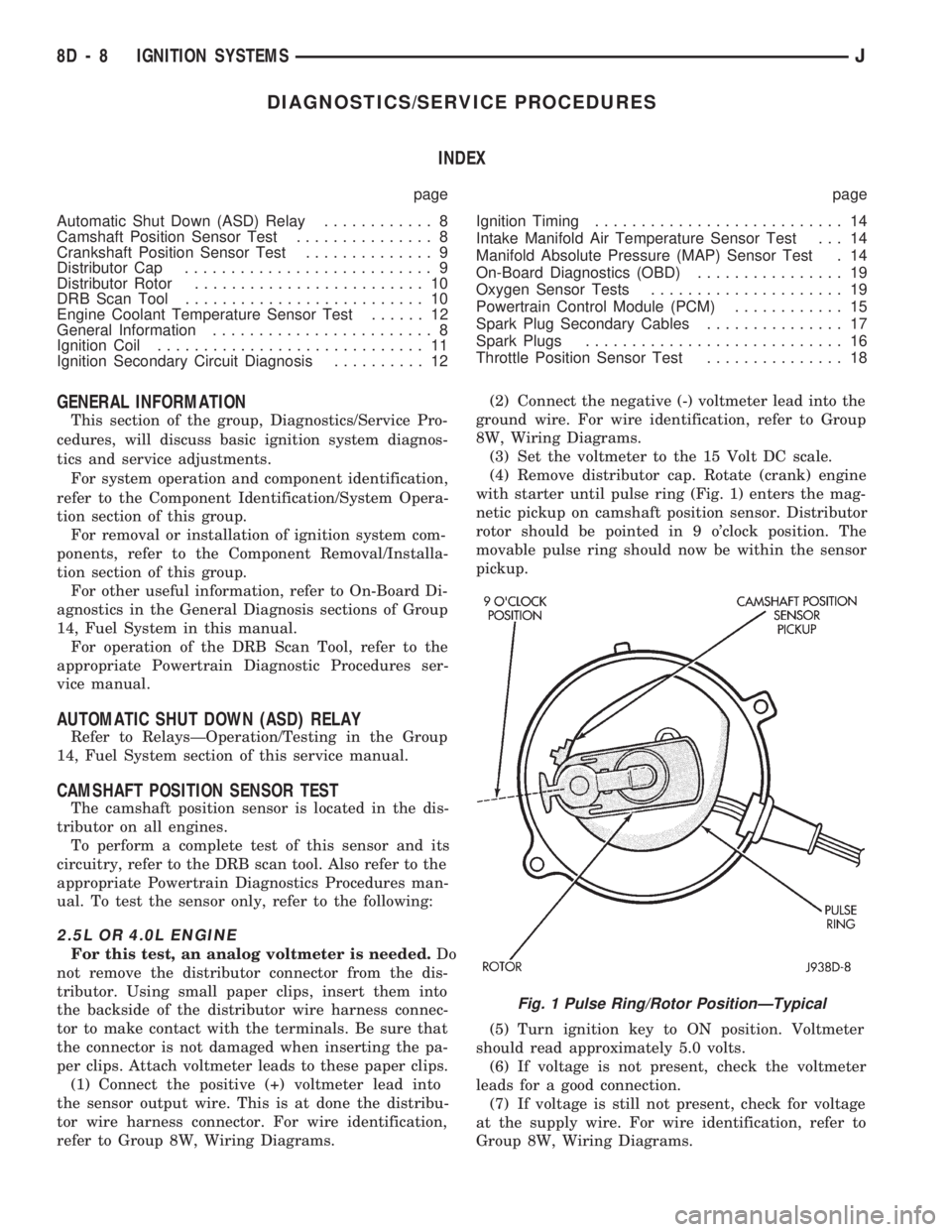
(4) Remove distributor cap. Rotate (crank) engine
with starter until pulse ring (Fig. 1) enters the mag-
netic pickup on camshaft position sensor. Distributor
rotor should be pointed in 9 o'clock position. The
movable pulse ring should now be within the sensor
pickup.
(5) Turn ignition key to ON position. Voltmeter
should read approximately 5.0 volts.
(6) If voltage is not present, check the voltmeter
leads for a good connection.
(7) If voltage is still not present, check for voltage
at the supply wire. For wire identification, refer to
Group 8W, Wiring Diagrams.
Fig. 1 Pulse Ring/Rotor PositionÐTypical
8D - 8 IGNITION SYSTEMSJ
Page 322 of 1784
(8) If voltage is not present at supply wire, check
for voltage at pin 7 of Powertrain Control Module
(PCM) 60-way connector. Leave the PCM connector
connected for this test.
(9) If voltage is still not present, perform vehicle
test using the DRB scan tool.
(10) If voltage is present at pin 7, but not at the
supply wire:
(a) Check continuity between the supply wire.
This is checked between the distributor connector
and pin 7 at the PCM. If continuity is not present,
repair the harness as necessary.
(b) Check for continuity between the camshaft
position sensor output wire and pin 44 at the PCM.
If continuity is not present, repair the harness as
necessary.
(c) Check for continuity between the ground cir-
cuit wire at the distributor connector and ground.
If continuity is not present, repair the harness as
necessary.
(11) While observing the voltmeter, crank the en-
gine with ignition switch. The voltmeter needle
should fluctuate between 0 and 5 volts while the en-
gine is cranking. This verifies that the camshaft po-
sition sensor in the distributor is operating properly
and a sync pulse signal is being generated.
If sync pulse signal is not present, replacement of
the camshaft position sensor is necessary.
For removal or installation of ignition system com-
ponents, refer to the Component Removal/Installa-
tion section of this group.
For system operation and component identification,
refer to the Component Identification/System Opera-
tion section of this group.
CRANKSHAFT POSITION SENSOR TEST
To perform a complete test of this sensor and its
circuitry, refer to the DRB scan tool. Also refer to the
appropriate Powertrain Diagnostics Procedures man-
ual. To test the sensor only, refer to the following:
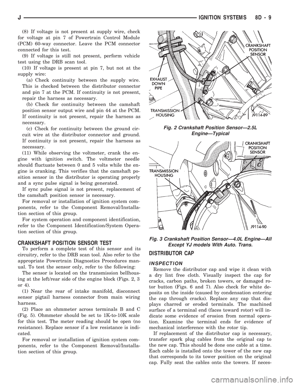
The sensor is located on the transmission bellhous-
ing at the left/rear side of the engine block (Figs. 2, 3
or 4).
(1) Near the rear of intake manifold, disconnect
sensor pigtail harness connector from main wiring
harness.
(2) Place an ohmmeter across terminals B and C
(Fig. 5). Ohmmeter should be set to 1K-to-10K scale
for this test. The meter reading should be open (no
resistance). Replace sensor if a low resistance is indi-
cated.
For removal or installation of ignition system com-
ponents, refer to the Component Removal/Installa-
tion section of this group.
DISTRIBUTOR CAP
INSPECTION
Remove the distributor cap and wipe it clean with
a dry lint free cloth. Visually inspect the cap for
cracks, carbon paths, broken towers, or damaged ro-
tor button (Figs. 6 and 7). Also check for white de-
posits on the inside (caused by condensation entering
the cap through cracks). Replace any cap that dis-
plays charred or eroded terminals. The machined
surface of a terminal end (faces toward rotor) will in-
dicate some evidence of erosion from normal opera-
tion. Examine the terminal ends for evidence of
mechanical interference with the rotor tip.
If replacement of the distributor cap is necessary,
transfer spark plug cables from the original cap to
the new cap. This should be done one cable at a time.
Each cable is installed onto the tower of the new cap
that corresponds to its tower position on the original
cap. Fully seat the cables onto the towers. If neces-
Fig. 2 Crankshaft Position SensorÐ2.5L
EngineÐTypical
Fig. 3 Crankshaft Position SensorÐ4.0L EngineÐAll
Except YJ models With Auto. Trans.
JIGNITION SYSTEMS 8D - 9