check engine JEEP CHEROKEE 1994 Service Manual PDF
[x] Cancel search | Manufacturer: JEEP, Model Year: 1994, Model line: CHEROKEE, Model: JEEP CHEROKEE 1994Pages: 1784, PDF Size: 77.09 MB
Page 268 of 1784
CAUTION: When installing the serpentine accessory
drive belt, the belt MUST be routed correctly. If not,
the engine may overheat due to the water pump ro-
tating in the wrong direction. Refer to (Figs. 2, 3, 4
or 5) for correct belt routing.
(6) Install new belt. Refer to the end of this group
for Drive Belt Tension specifications.
(7) Tighten pump adjusting bolt D (Fig. 8) to at-
tain proper belt tension.(8) Tighten rear pump mounting bolts, pivot bolt
and lock nut to 27 Nzm (20 ft. lbs.) torque.
(9) After power steering pump has been tightened
into position, recheck belt tension. Adjust if neces-
sary.
BELT SERVICEÐWITH RIGHT HAND DRIVE
The following procedures are for XJ models
equipped with right hand drive (RHD) and a 4.0L en-
gine.
REMOVAL
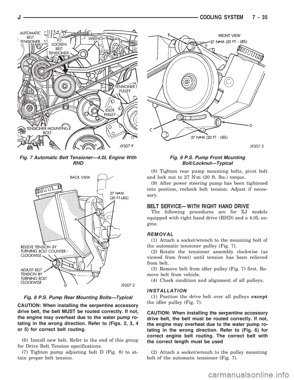
(1) Attach a socket/wrench to the mounting bolt of
the automatic tensioner pulley (Fig. 7).
(2) Rotate the tensioner assembly clockwise (as
viewed from front) until tension has been relieved
from belt.
(3) Remove belt from idler pulley (Fig. 7) first. Re-
move belt from vehicle.
(4) Check condition and alignment of all pulleys.
INSTALLATION
(1) Position the drive belt over all pulleysexcept
the idler pulley (Fig. 7).
CAUTION: When installing the serpentine accessory
drive belt, the belt must be routed correctly. If not,
the engine may overheat due to the water pump ro-
tating in the wrong direction. Refer to (Fig. 6) for
correct engine belt routing. The correct belt with
the correct length must be used
(2) Attach a socket/wrench to the pulley mounting
bolt of the automatic tensioner (Fig. 7).
Fig. 7 Automatic Belt TensionerÐ4.0L Engine With
RHD
Fig. 8 P.S. Pump Rear Mounting BoltsÐTypical
Fig. 9 P.S. Pump Front Mounting
Bolt/LocknutÐTypical
JCOOLING SYSTEM 7 - 35
Page 284 of 1784
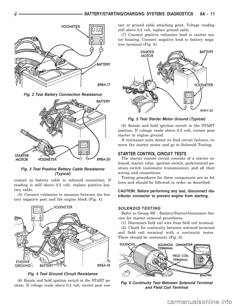
contact at battery cable to solenoid connection. If
reading is still above 0.2 volt, replace positive bat-
tery cable.
(5) Connect voltmeter to measure between the bat-
tery negative post and the engine block (Fig. 4).
(6) Rotate and hold ignition switch in the START po-
sition. If voltage reads above 0.2 volt, correct poor con-tact at ground cable attaching point. Voltage reading
still above 0.2 volt, replace ground cable.
(7) Connect positive voltmeter lead to starter mo-
tor housing. Connect negative lead to battery nega-
tive terminal (Fig. 5).
(8) Rotate and hold ignition switch in the START
position. If voltage reads above 0.2 volt, correct poor
starter to engine ground.
If resistance tests detect no feed circuit failures, re-
move the starter motor and go to Solenoid Testing.
STARTER CONTROL CIRCUIT TESTS
The starter control circuit consists of a starter so-
lenoid, starter relay, ignition switch, park/neutral po-
sition switch (automatic transmission), and all their
wiring and connections.
Testing procedures for these components are as fol-
lows and should be followed in order as described.
CAUTION: Before performing any test, disconnect dis-
tributor connector to prevent engine from starting.
SOLENOID TESTING
Refer to Group 8B - Battery/Starter/Generator Ser-
vice for starter removal procedures.
(1) Disconnect field coil wire from field coil terminal.
(2) Check for continuity between solenoid terminal
and field coil terminal with a continuity tester.
There should be continuity (Fig. 6).
Fig. 2 Test Battery Connection Resistance
Fig. 3 Test Positive Battery Cable Resistance
(Typical)
Fig. 4 Test Ground Circuit Resistance
Fig. 5 Test Starter Motor Ground (Typical)
Fig. 6 Continuity Test Between Solenoid Terminal
and Field Coil Terminal
JBATTERY/STARTING/CHARGING SYSTEMS DIAGNOSTICS 8A - 11
Page 286 of 1784
IGNITION SWITCH TEST
After testing starter solenoid and relay and they
check out OK, trouble is probably with ignition
switch or its wiring.
Check all wiring for opens and shorts, and connec-
tions for being loose or corroded.
PARK/NEUTRAL POSITION SWITCH
Refer to Group 21 - Transmissions for diagnostic
information.
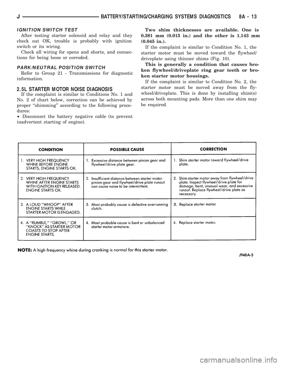
2.5L STARTER MOTOR NOISE DIAGNOSIS
If the complaint is similar to Conditions No. 1 and
No. 2 of chart below, correction can be achieved by
proper ``shimming'' according to the following proce-
dures:
²Disconnect the battery negative cable (to prevent
inadvertent starting of engine).Two shim thicknesses are available. One is
0.381 mm (0.015 in.) and the other is 1.143 mm
(0.045 in.).
If the complaint is similar to Condition No. 1, the
starter motor must be moved toward the flywheel/
driveplate using thinner shims (Fig. 10).
This is generally a condition that causes bro-
ken flywheel/driveplate ring gear teeth or bro-
ken starter motor housings.
If the complaint is similar to Condition No. 2, the
starter motor must be moved away from the fly-
wheel/driveplate. This is done by installing shim(s)
across both mounting pads. More than one shim may
be required.
JBATTERY/STARTING/CHARGING SYSTEMS DIAGNOSTICS 8A - 13
Page 287 of 1784
GENERATOR TEST PROCEDURES ON VEHICLE
INDEX
page page
Diagnostic Procedures..................... 15
General Information....................... 14Operational Check with Battery Indicator
(Base Cluster Only)..................... 14
Operational Check with Voltmeter............ 15
GENERAL INFORMATION
The generator is belt-driven by the engine. All en-
gines use serpentine drive.
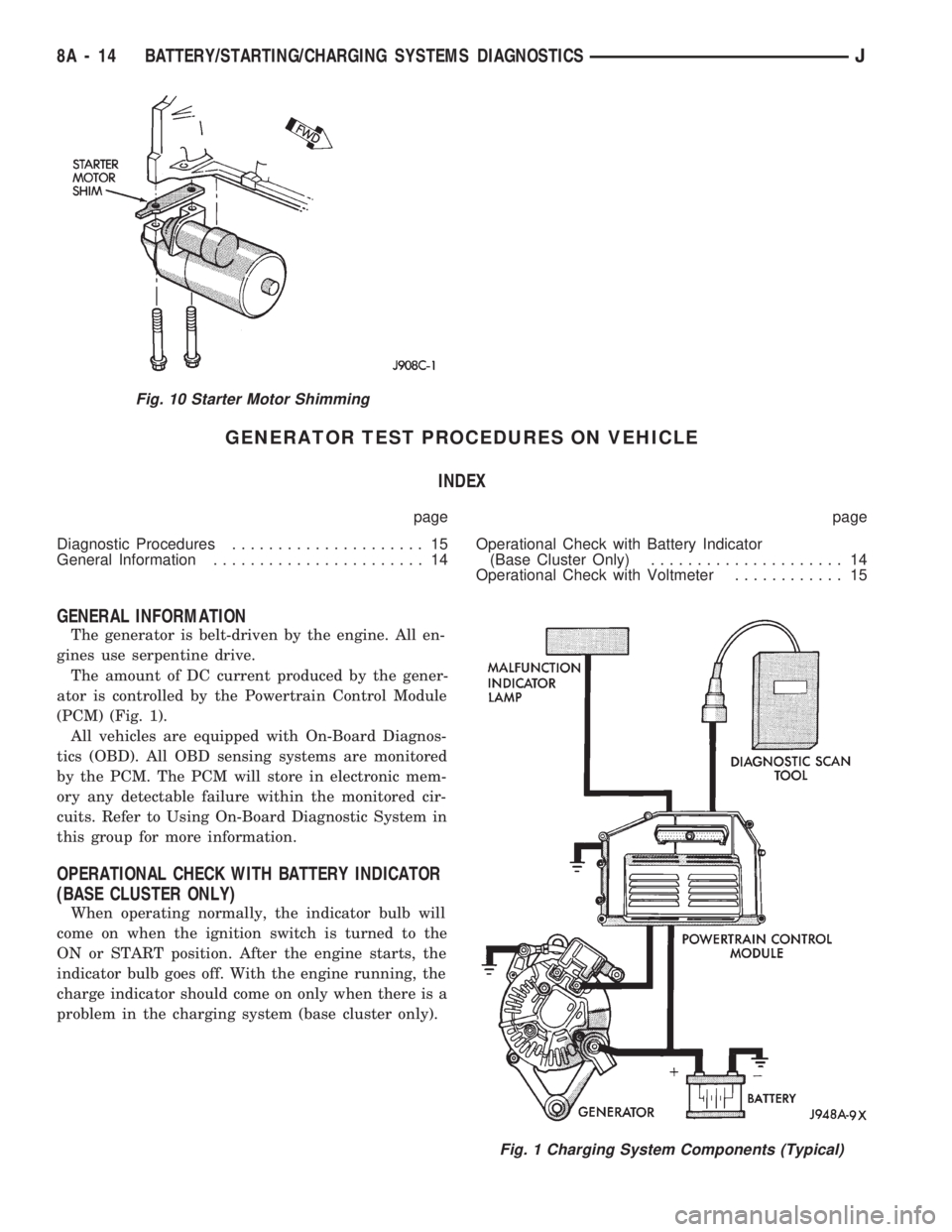
The amount of DC current produced by the gener-
ator is controlled by the Powertrain Control Module
(PCM) (Fig. 1).
All vehicles are equipped with On-Board Diagnos-
tics (OBD). All OBD sensing systems are monitored
by the PCM. The PCM will store in electronic mem-
ory any detectable failure within the monitored cir-
cuits. Refer to Using On-Board Diagnostic System in
this group for more information.
OPERATIONAL CHECK WITH BATTERY INDICATOR
(BASE CLUSTER ONLY)
When operating normally, the indicator bulb will
come on when the ignition switch is turned to the
ON or START position. After the engine starts, the
indicator bulb goes off. With the engine running, the
charge indicator should come on only when there is a
problem in the charging system (base cluster only).
Fig. 10 Starter Motor Shimming
Fig. 1 Charging System Components (Typical)
8A - 14 BATTERY/STARTING/CHARGING SYSTEMS DIAGNOSTICSJ
Page 288 of 1784
OPERATIONAL CHECK WITH VOLTMETER
When the ignition switch is turned to the ON po-
sition, battery potential will register on the voltme-
ter. During engine cranking a lower voltage will
appear on the meter. With the engine running, a
voltage reading higher than the first reading (igni-
tion in ON) should register.
DIAGNOSTIC PROCEDURES
If the indicator operates abnormally, or if an un-
dercharged or overcharged battery condition occurs,
the following procedures may be used to diagnose the
charging system.
Remember that an undercharged battery is often
caused by:
²accessories being left on overnight
²or by a defective switch which allows a bulb, such
as a liftgate or glove box light, to stay on (refer to
Ignition Off Draw Diagnosis).
VISUAL INSPECTION
²Inspect condition of battery cable terminals, bat-
tery posts, connections at engine block, starter motor
solenoid and relay. They should be clean and tight.
Repair as required.
²Inspect all fuses in the fuse block for tightness in
receptacles. They should be properly installed and
tight. Repair or replace as required.²Inspect the electrolyte level in the battery and add
water if necessary.
²Inspect generator mounting bolts for tightness. Re-
place or torque bolt as required. Refer to Torque
Specifications in Battery/Starter/Generator Service.
²Inspect generator drive belt condition and tension.
Tension or replace belt as required. Refer to Belt
Tension Specifications in Battery/Starter/Generator
Service.
²Inspect connection at generator B+ output. It
should be clean and tight. Repair as required.
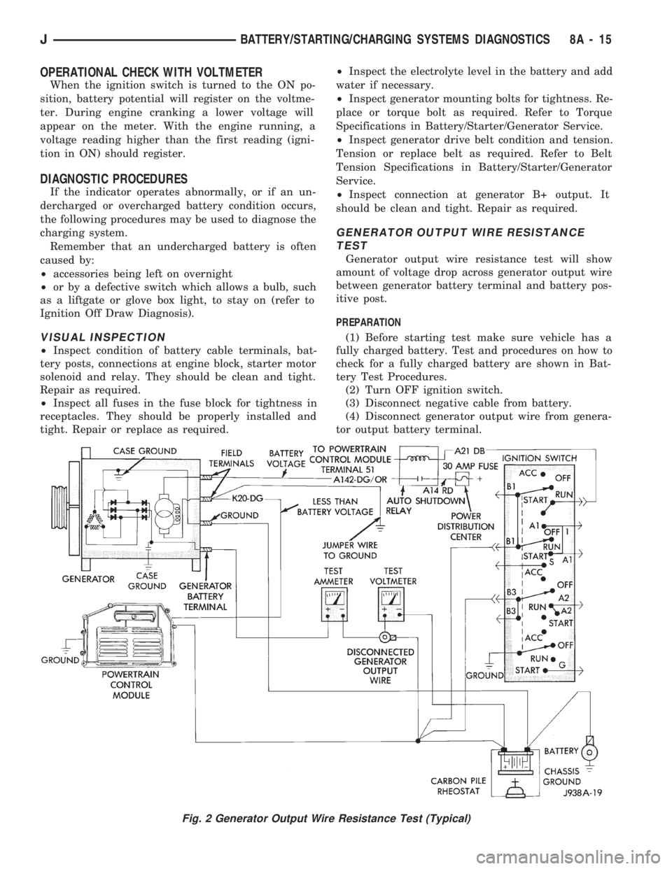
GENERATOR OUTPUT WIRE RESISTANCE
TEST
Generator output wire resistance test will show
amount of voltage drop across generator output wire
between generator battery terminal and battery pos-
itive post.
PREPARATION
(1) Before starting test make sure vehicle has a
fully charged battery. Test and procedures on how to
check for a fully charged battery are shown in Bat-
tery Test Procedures.
(2) Turn OFF ignition switch.
(3) Disconnect negative cable from battery.
(4) Disconnect generator output wire from genera-
tor output battery terminal.
Fig. 2 Generator Output Wire Resistance Test (Typical)
JBATTERY/STARTING/CHARGING SYSTEMS DIAGNOSTICS 8A - 15
Page 289 of 1784
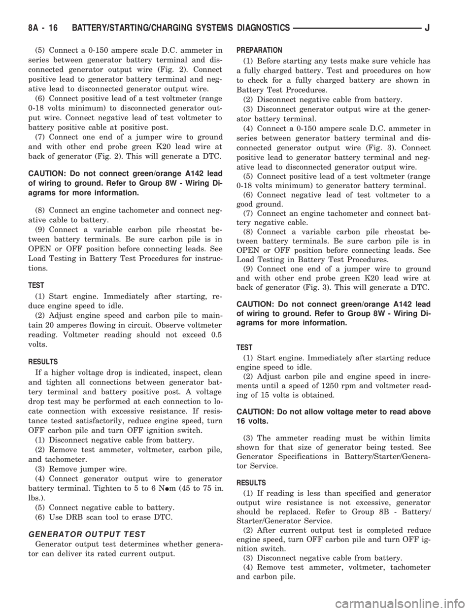
(5) Connect a 0-150 ampere scale D.C. ammeter in
series between generator battery terminal and dis-
connected generator output wire (Fig. 2). Connect
positive lead to generator battery terminal and neg-
ative lead to disconnected generator output wire.
(6) Connect positive lead of a test voltmeter (range
0-18 volts minimum) to disconnected generator out-
put wire. Connect negative lead of test voltmeter to
battery positive cable at positive post.
(7) Connect one end of a jumper wire to ground
and with other end probe green K20 lead wire at
back of generator (Fig. 2). This will generate a DTC.
CAUTION: Do not connect green/orange A142 lead
of wiring to ground. Refer to Group 8W - Wiring Di-
agrams for more information.
(8) Connect an engine tachometer and connect neg-
ative cable to battery.
(9) Connect a variable carbon pile rheostat be-
tween battery terminals. Be sure carbon pile is in
OPEN or OFF position before connecting leads. See
Load Testing in Battery Test Procedures for instruc-
tions.
TEST
(1) Start engine. Immediately after starting, re-
duce engine speed to idle.
(2) Adjust engine speed and carbon pile to main-
tain 20 amperes flowing in circuit. Observe voltmeter
reading. Voltmeter reading should not exceed 0.5
volts.
RESULTS
If a higher voltage drop is indicated, inspect, clean
and tighten all connections between generator bat-
tery terminal and battery positive post. A voltage
drop test may be performed at each connection to lo-
cate connection with excessive resistance. If resis-
tance tested satisfactorily, reduce engine speed, turn
OFF carbon pile and turn OFF ignition switch.
(1) Disconnect negative cable from battery.
(2) Remove test ammeter, voltmeter, carbon pile,
and tachometer.
(3) Remove jumper wire.
(4) Connect generator output wire to generator
battery terminal. Tighten to 5 to 6 NIm (45 to 75 in.
lbs.).
(5) Connect negative cable to battery.
(6) Use DRB scan tool to erase DTC.
GENERATOR OUTPUT TEST
Generator output test determines whether genera-
tor can deliver its rated current output.PREPARATION
(1) Before starting any tests make sure vehicle has
a fully charged battery. Test and procedures on how
to check for a fully charged battery are shown in
Battery Test Procedures.
(2) Disconnect negative cable from battery.
(3) Disconnect generator output wire at the gener-
ator battery terminal.
(4) Connect a 0-150 ampere scale D.C. ammeter in
series between generator battery terminal and dis-
connected generator output wire (Fig. 3). Connect
positive lead to generator battery terminal and neg-
ative lead to disconnected generator output wire.
(5) Connect positive lead of a test voltmeter (range
0-18 volts minimum) to generator battery terminal.
(6) Connect negative lead of test voltmeter to a
good ground.
(7) Connect an engine tachometer and connect bat-
tery negative cable.
(8) Connect a variable carbon pile rheostat be-
tween battery terminals. Be sure carbon pile is in
OPEN or OFF position before connecting leads. See
Load Testing in Battery Test Procedures.
(9) Connect one end of a jumper wire to ground
and with other end probe green K20 lead wire at
back of generator (Fig. 3). This will generate a DTC.
CAUTION: Do not connect green/orange A142 lead
of wiring to ground. Refer to Group 8W - Wiring Di-
agrams for more information.
TEST
(1) Start engine. Immediately after starting reduce
engine speed to idle.
(2) Adjust carbon pile and engine speed in incre-
ments until a speed of 1250 rpm and voltmeter read-
ing of 15 volts is obtained.
CAUTION: Do not allow voltage meter to read above
16 volts.
(3) The ammeter reading must be within limits
shown for that size of generator being tested. See
Generator Specifications in Battery/Starter/Genera-
tor Service.
RESULTS
(1) If reading is less than specified and generator
output wire resistance is not excessive, generator
should be replaced. Refer to Group 8B - Battery/
Starter/Generator Service.
(2) After current output test is completed reduce
engine speed, turn OFF carbon pile and turn OFF ig-
nition switch.
(3) Disconnect negative cable from battery.
(4) Remove test ammeter, voltmeter, tachometer
and carbon pile.
8A - 16 BATTERY/STARTING/CHARGING SYSTEMS DIAGNOSTICSJ
Page 292 of 1784
USING ON-BOARD DIAGNOSTIC SYSTEM
OPERATION OF ON-BOARD DIAGNOSTIC
(OBD) SYSTEM
The Powertrain Control Module (PCM) monitors
critical input and output circuits of the charging sys-
tem making sure they are OK. Some are checked
continuously and some are checked only under cer-
tain conditions.
If OBD system senses that one critical circuit is
bad during the monitoring cycle, it will put a diag-
nostic trouble code into memory. Each input and out-
put circuit monitored by the OBD system has its own
diagnostic trouble code. The diagnostic trouble code
(DTC) will stay in memory as long as the circuit con-
tinues to be bad. If the problem does not happen
again after the fault code is put into memory, the
PCM is programmed to clear the memory after 50 en-
gine starts.
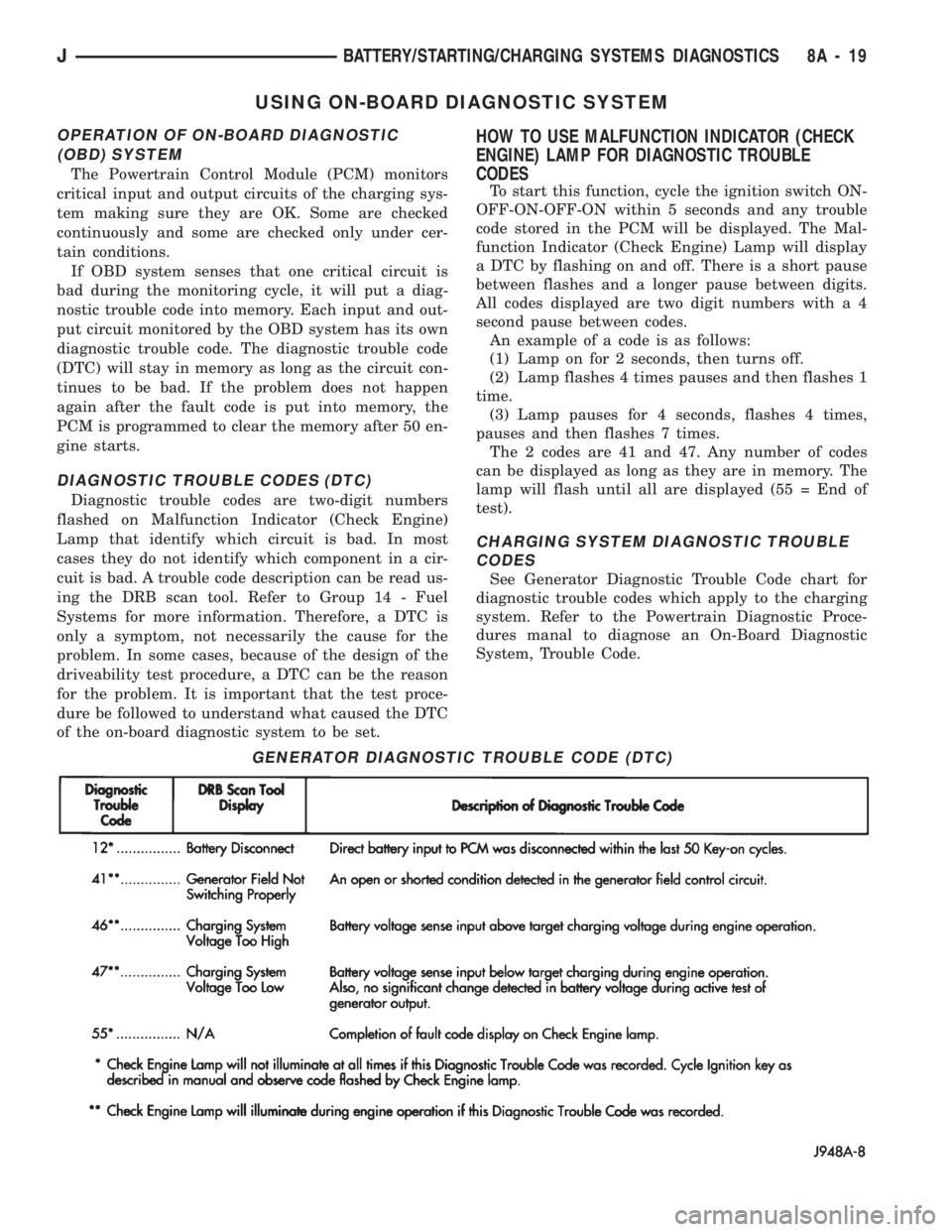
DIAGNOSTIC TROUBLE CODES (DTC)
Diagnostic trouble codes are two-digit numbers
flashed on Malfunction Indicator (Check Engine)
Lamp that identify which circuit is bad. In most
cases they do not identify which component in a cir-
cuit is bad. A trouble code description can be read us-
ing the DRB scan tool. Refer to Group 14 - Fuel
Systems for more information. Therefore, a DTC is
only a symptom, not necessarily the cause for the
problem. In some cases, because of the design of the
driveability test procedure, a DTC can be the reason
for the problem. It is important that the test proce-
dure be followed to understand what caused the DTC
of the on-board diagnostic system to be set.
HOW TO USE MALFUNCTION INDICATOR (CHECK
ENGINE) LAMP FOR DIAGNOSTIC TROUBLE
CODES
To start this function, cycle the ignition switch ON-
OFF-ON-OFF-ON within 5 seconds and any trouble
code stored in the PCM will be displayed. The Mal-
function Indicator (Check Engine) Lamp will display
a DTC by flashing on and off. There is a short pause
between flashes and a longer pause between digits.
All codes displayed are two digit numbers with a 4
second pause between codes.
An example of a code is as follows:
(1) Lamp on for 2 seconds, then turns off.
(2) Lamp flashes 4 times pauses and then flashes 1
time.
(3) Lamp pauses for 4 seconds, flashes 4 times,
pauses and then flashes 7 times.
The 2 codes are 41 and 47. Any number of codes
can be displayed as long as they are in memory. The
lamp will flash until all are displayed (55 = End of
test).
CHARGING SYSTEM DIAGNOSTIC TROUBLE
CODES
See Generator Diagnostic Trouble Code chart for
diagnostic trouble codes which apply to the charging
system. Refer to the Powertrain Diagnostic Proce-
dures manal to diagnose an On-Board Diagnostic
System, Trouble Code.
GENERATOR DIAGNOSTIC TROUBLE CODE (DTC)
JBATTERY/STARTING/CHARGING SYSTEMS DIAGNOSTICS 8A - 19
Page 294 of 1784
BATTERY/STARTER/GENERATOR SERVICE
CONTENTS
page page
BATTERY SERVICE PROCEDURES.......... 1
ENGINE STARTER MOTOR SERVICE
PROCEDURES......................... 4GENERATOR SERVICE PROCEDURES........ 7
SPECIFICATIONS....................... 10
BATTERY SERVICE PROCEDURES
GENERAL INFORMATION
This section covers battery removal and installa-
tion procedures only. For diagnostic procedures, refer
to Group 8A - Battery/Starting/Charging Systems Di-
agnostics.
BATTERY MAINTENANCE
(1) Inspect cable terminals for corrosion and dam-
age. Remove the corrosion using a wire brush, or
post and terminal cleaner, and a sodium bicarbonate/
water solution. Replace cables that have damaged or
deformed terminals.
Be sure filler caps or vents are installed when
washing battery to prevent solution from enter-
ing battery.
(2) Clean outside of battery case if the original
battery is to be installed. Clean top cover with di-
luted ammonia or a sodium bicarbonate/water solu-
tion to remove acid film. Flush with clean water.
Ensure that cleaning solution does not enter cells.
(3) Remove corrosion from the terminals with a
wire brush or post and terminal cleaner. Inspect the
case for cracks or other damage that would result in
leakage of electrolyte.
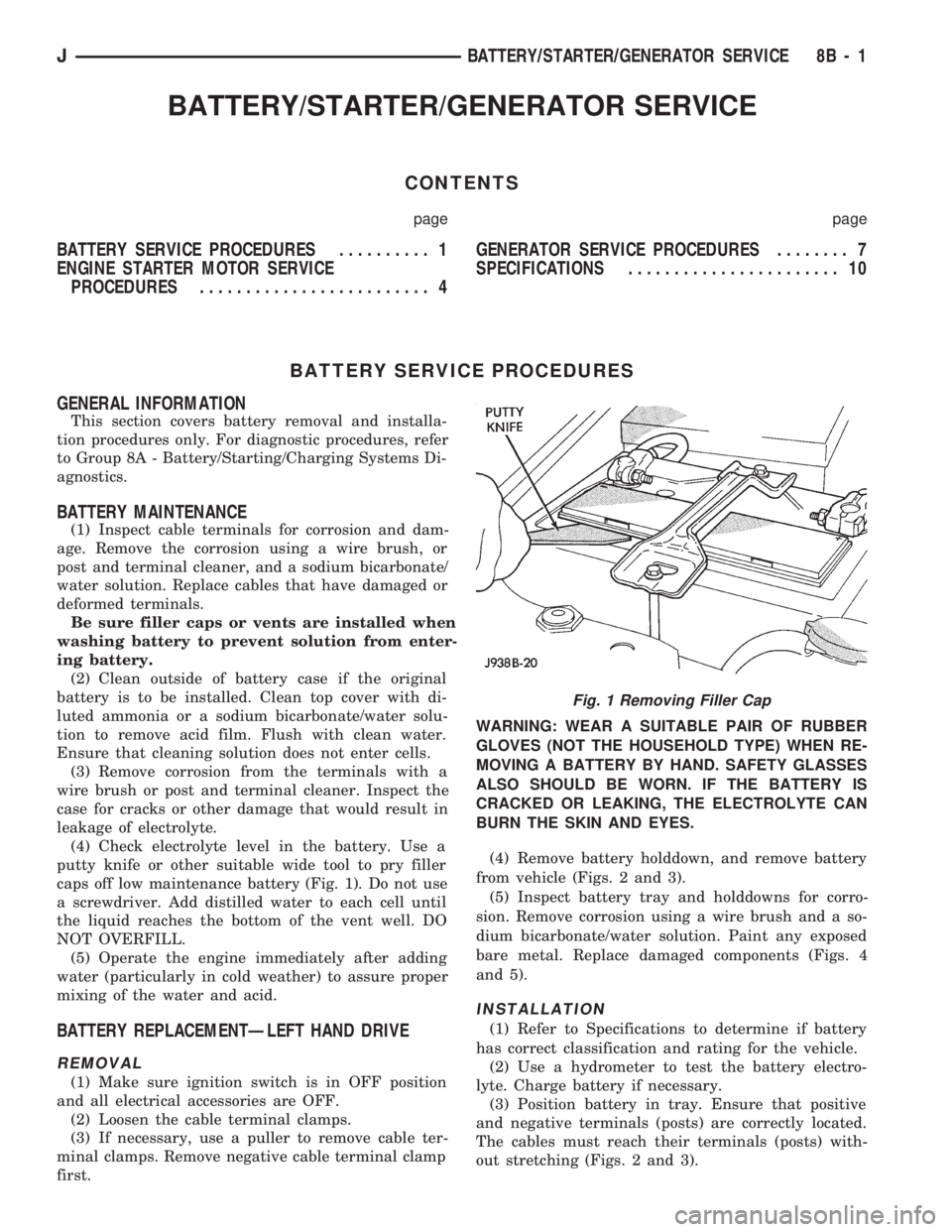
(4) Check electrolyte level in the battery. Use a
putty knife or other suitable wide tool to pry filler
caps off low maintenance battery (Fig. 1). Do not use
a screwdriver. Add distilled water to each cell until
the liquid reaches the bottom of the vent well. DO
NOT OVERFILL.
(5) Operate the engine immediately after adding
water (particularly in cold weather) to assure proper
mixing of the water and acid.
BATTERY REPLACEMENTÐLEFT HAND DRIVE
REMOVAL
(1) Make sure ignition switch is in OFF position
and all electrical accessories are OFF.
(2) Loosen the cable terminal clamps.
(3) If necessary, use a puller to remove cable ter-
minal clamps. Remove negative cable terminal clamp
first.WARNING: WEAR A SUITABLE PAIR OF RUBBER
GLOVES (NOT THE HOUSEHOLD TYPE) WHEN RE-
MOVING A BATTERY BY HAND. SAFETY GLASSES
ALSO SHOULD BE WORN. IF THE BATTERY IS
CRACKED OR LEAKING, THE ELECTROLYTE CAN
BURN THE SKIN AND EYES.
(4) Remove battery holddown, and remove battery
from vehicle (Figs. 2 and 3).
(5) Inspect battery tray and holddowns for corro-
sion. Remove corrosion using a wire brush and a so-
dium bicarbonate/water solution. Paint any exposed
bare metal. Replace damaged components (Figs. 4
and 5).
INSTALLATION
(1) Refer to Specifications to determine if battery
has correct classification and rating for the vehicle.
(2) Use a hydrometer to test the battery electro-
lyte. Charge battery if necessary.
(3) Position battery in tray. Ensure that positive
and negative terminals (posts) are correctly located.
The cables must reach their terminals (posts) with-
out stretching (Figs. 2 and 3).
Fig. 1 Removing Filler Cap
JBATTERY/STARTER/GENERATOR SERVICE 8B - 1
Page 321 of 1784
DIAGNOSTICS/SERVICE PROCEDURES
INDEX
page page
Automatic Shut Down (ASD) Relay............ 8
Camshaft Position Sensor Test............... 8
Crankshaft Position Sensor Test.............. 9
Distributor Cap........................... 9
Distributor Rotor......................... 10
DRB Scan Tool.......................... 10
Engine Coolant Temperature Sensor Test...... 12
General Information........................ 8
Ignition Coil............................. 11
Ignition Secondary Circuit Diagnosis.......... 12Ignition Timing........................... 14
Intake Manifold Air Temperature Sensor Test . . . 14
Manifold Absolute Pressure (MAP) Sensor Test . 14
On-Board Diagnostics (OBD)................ 19
Oxygen Sensor Tests..................... 19
Powertrain Control Module (PCM)............ 15
Spark Plug Secondary Cables............... 17
Spark Plugs............................ 16
Throttle Position Sensor Test............... 18
GENERAL INFORMATION
This section of the group, Diagnostics/Service Pro-
cedures, will discuss basic ignition system diagnos-
tics and service adjustments.
For system operation and component identification,
refer to the Component Identification/System Opera-
tion section of this group.
For removal or installation of ignition system com-
ponents, refer to the Component Removal/Installa-
tion section of this group.
For other useful information, refer to On-Board Di-
agnostics in the General Diagnosis sections of Group
14, Fuel System in this manual.
For operation of the DRB Scan Tool, refer to the
appropriate Powertrain Diagnostic Procedures ser-
vice manual.
AUTOMATIC SHUT DOWN (ASD) RELAY
Refer to RelaysÐOperation/Testing in the Group
14, Fuel System section of this service manual.
CAMSHAFT POSITION SENSOR TEST
The camshaft position sensor is located in the dis-
tributor on all engines.
To perform a complete test of this sensor and its
circuitry, refer to the DRB scan tool. Also refer to the
appropriate Powertrain Diagnostics Procedures man-
ual. To test the sensor only, refer to the following:
2.5L OR 4.0L ENGINE
For this test, an analog voltmeter is needed.Do
not remove the distributor connector from the dis-
tributor. Using small paper clips, insert them into
the backside of the distributor wire harness connec-
tor to make contact with the terminals. Be sure that
the connector is not damaged when inserting the pa-
per clips. Attach voltmeter leads to these paper clips.
(1) Connect the positive (+) voltmeter lead into
the sensor output wire. This is at done the distribu-
tor wire harness connector. For wire identification,
refer to Group 8W, Wiring Diagrams.(2) Connect the negative (-) voltmeter lead into the
ground wire. For wire identification, refer to Group
8W, Wiring Diagrams.
(3) Set the voltmeter to the 15 Volt DC scale.
(4) Remove distributor cap. Rotate (crank) engine
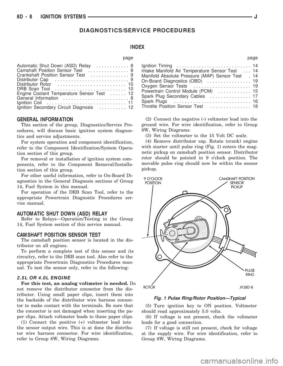
with starter until pulse ring (Fig. 1) enters the mag-
netic pickup on camshaft position sensor. Distributor
rotor should be pointed in 9 o'clock position. The
movable pulse ring should now be within the sensor
pickup.
(5) Turn ignition key to ON position. Voltmeter
should read approximately 5.0 volts.
(6) If voltage is not present, check the voltmeter
leads for a good connection.
(7) If voltage is still not present, check for voltage
at the supply wire. For wire identification, refer to
Group 8W, Wiring Diagrams.
Fig. 1 Pulse Ring/Rotor PositionÐTypical
8D - 8 IGNITION SYSTEMSJ
Page 322 of 1784
(8) If voltage is not present at supply wire, check
for voltage at pin 7 of Powertrain Control Module
(PCM) 60-way connector. Leave the PCM connector
connected for this test.
(9) If voltage is still not present, perform vehicle
test using the DRB scan tool.
(10) If voltage is present at pin 7, but not at the
supply wire:
(a) Check continuity between the supply wire.
This is checked between the distributor connector
and pin 7 at the PCM. If continuity is not present,
repair the harness as necessary.
(b) Check for continuity between the camshaft
position sensor output wire and pin 44 at the PCM.
If continuity is not present, repair the harness as
necessary.
(c) Check for continuity between the ground cir-
cuit wire at the distributor connector and ground.
If continuity is not present, repair the harness as
necessary.
(11) While observing the voltmeter, crank the en-
gine with ignition switch. The voltmeter needle
should fluctuate between 0 and 5 volts while the en-
gine is cranking. This verifies that the camshaft po-
sition sensor in the distributor is operating properly
and a sync pulse signal is being generated.
If sync pulse signal is not present, replacement of
the camshaft position sensor is necessary.
For removal or installation of ignition system com-
ponents, refer to the Component Removal/Installa-
tion section of this group.
For system operation and component identification,
refer to the Component Identification/System Opera-
tion section of this group.
CRANKSHAFT POSITION SENSOR TEST
To perform a complete test of this sensor and its
circuitry, refer to the DRB scan tool. Also refer to the
appropriate Powertrain Diagnostics Procedures man-
ual. To test the sensor only, refer to the following:
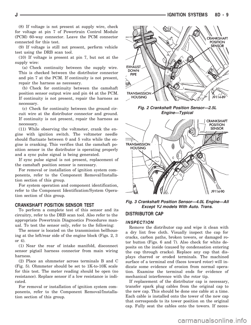
The sensor is located on the transmission bellhous-
ing at the left/rear side of the engine block (Figs. 2, 3
or 4).
(1) Near the rear of intake manifold, disconnect
sensor pigtail harness connector from main wiring
harness.
(2) Place an ohmmeter across terminals B and C
(Fig. 5). Ohmmeter should be set to 1K-to-10K scale
for this test. The meter reading should be open (no
resistance). Replace sensor if a low resistance is indi-
cated.
For removal or installation of ignition system com-
ponents, refer to the Component Removal/Installa-
tion section of this group.
DISTRIBUTOR CAP
INSPECTION
Remove the distributor cap and wipe it clean with
a dry lint free cloth. Visually inspect the cap for
cracks, carbon paths, broken towers, or damaged ro-
tor button (Figs. 6 and 7). Also check for white de-
posits on the inside (caused by condensation entering
the cap through cracks). Replace any cap that dis-
plays charred or eroded terminals. The machined
surface of a terminal end (faces toward rotor) will in-
dicate some evidence of erosion from normal opera-
tion. Examine the terminal ends for evidence of
mechanical interference with the rotor tip.
If replacement of the distributor cap is necessary,
transfer spark plug cables from the original cap to
the new cap. This should be done one cable at a time.
Each cable is installed onto the tower of the new cap
that corresponds to its tower position on the original
cap. Fully seat the cables onto the towers. If neces-
Fig. 2 Crankshaft Position SensorÐ2.5L
EngineÐTypical
Fig. 3 Crankshaft Position SensorÐ4.0L EngineÐAll
Except YJ models With Auto. Trans.
JIGNITION SYSTEMS 8D - 9