fuel JEEP CHEROKEE 1994 Service Manual Online
[x] Cancel search | Manufacturer: JEEP, Model Year: 1994, Model line: CHEROKEE, Model: JEEP CHEROKEE 1994Pages: 1784, PDF Size: 77.09 MB
Page 318 of 1784
As coolant temperature varies, the sensor resistance
will change, resulting in a different input voltage to
the PCM.
When the engine is cold, the PCM will operate in
the Open Loop Cycle. It will demand slightly richer
air-fuel mixtures and higher idle speeds, until nor-
mal operating temperatures are reached. Refer to
Modes Of Operation in Group 14, Fuel System for a
description of Open and Closed Loop operation.
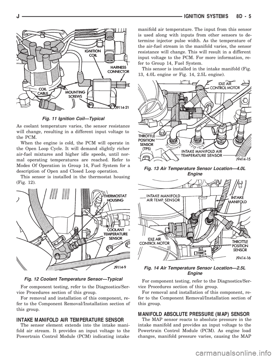
This sensor is installed in the thermostat housing
(Fig. 12).
For component testing, refer to the Diagnostics/Ser-
vice Procedures section of this group.
For removal and installation of this component, re-
fer to the Component Removal/Installation section of
this group.
INTAKE MANIFOLD AIR TEMPERATURE SENSOR
The sensor element extends into the intake mani-
fold air stream. It provides an input voltage to the
Powertrain Control Module (PCM) indicating intakemanifold air temperature. The input from this sensor
is used along with inputs from other sensors to de-
termine injector pulse width. As the temperature of
the air-fuel stream in the manifold varies, the sensor
resistance will change. This will result in a different
input voltage to the PCM. For more information, re-
fer to Group 14, Fuel System.
This sensor is installed in the intake manifold (Fig.
13, 4.0L engine or Fig. 14, 2.5L engine).
For component testing, refer to the Diagnostics/Ser-
vice Procedures section of this group.
For removal and installation of this component, re-
fer to the Component Removal/Installation section of
this group.
MANIFOLD ABSOLUTE PRESSURE (MAP) SENSOR
The MAP sensor reacts to absolute pressure in the
intake manifold and provides an input voltage to the
Powertrain Control Module (PCM). As engine load
changes, manifold pressure varies, causing the MAP
Fig. 11 Ignition CoilÐTypical
Fig. 12 Coolant Temperature SensorÐTypical
Fig. 13 Air Temperature Sensor LocationÐ4.0L
Engine
Fig. 14 Air Temperature Sensor LocationÐ2.5L
Engine
JIGNITION SYSTEMS 8D - 5
Page 319 of 1784
sensor voltage to change. This change results in a
different input voltage to the PCM. The input volt-
age level supplies the PCM with information. This
relates to ambient barometric pressure during engine
start-up (cranking) and to engine load while the en-
gine is running. The PCM uses this input, along with
inputs from other sensors, to adjust air-fuel mixture.
For more information, refer to Group 14, Fuel Sys-
tem.
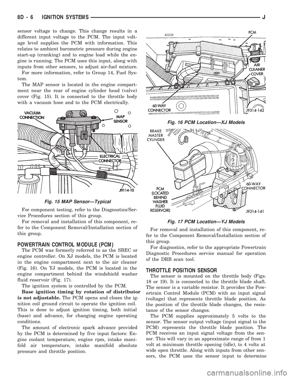
The MAP sensor is located in the engine compart-
ment near the rear of engine cylinder head (valve)
cover (Fig. 15). It is connected to the throttle body
with a vacuum hose and to the PCM electrically.
For component testing, refer to the Diagnostics/Ser-
vice Procedures section of this group.
For removal and installation of this component, re-
fer to the Component Removal/Installation section of
this group.
POWERTRAIN CONTROL MODULE (PCM)
The PCM was formerly referred to as the SBEC or
engine controller. On XJ models, the PCM is located
in the engine compartment next to the air cleaner
(Fig. 16). On YJ models, the PCM is located in the
engine compartment behind the windshield washer
fluid reservoir (Fig. 17).
The ignition system is controlled by the PCM.
Base ignition timing by rotation of distributor
is not adjustable.The PCM opens and closes the ig-
nition coil ground circuit to operate the ignition coil.
This is done to adjust ignition timing, both initial
(base) and advance, for changing engine operating
conditions.
The amount of electronic spark advance provided
by the PCM is determined by five input factors: En-
gine coolant temperature, engine rpm, intake mani-
fold air temperature, intake manifold absolute
pressure and throttle position.For removal and installation of this component, re-
fer to the Component Removal/Installation section of
this group.
For diagnostics, refer to the appropriate Powertrain
Diagnostic Procedures service manual for operation
of the DRB scan tool.
THROTTLE POSITION SENSOR
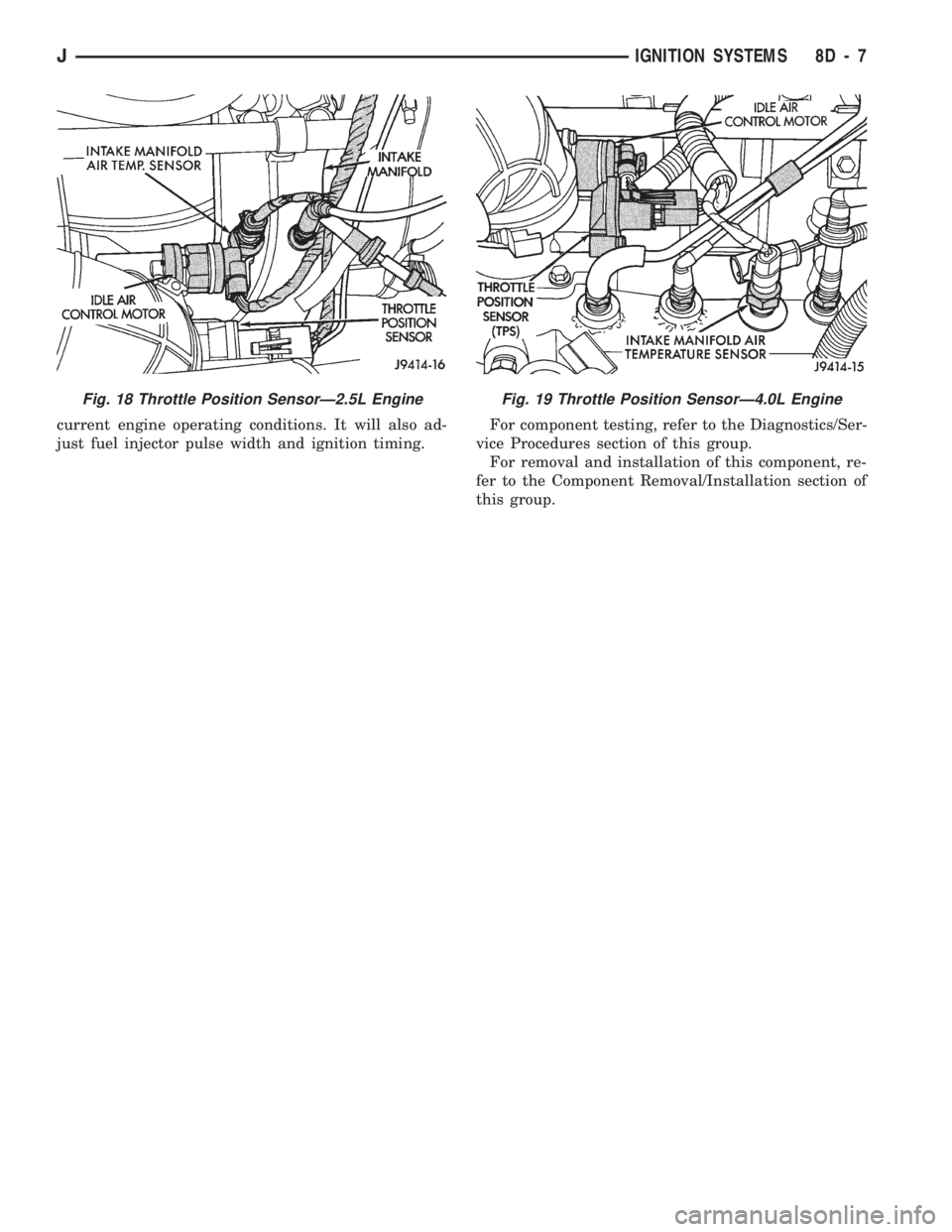
The sensor is mounted on the throttle body (Figs.
18 or 19). It is connected to the throttle blade shaft.
The sensor is a variable resistor. It provides the Pow-
ertrain Control Module (PCM) with an input signal
(voltage) that represents throttle blade position. As
the position of the throttle blade changes, the resis-
tance of the sensor changes.
The PCM supplies approximately 5 volts to the
sensor. The sensor output voltage (input signal to the
PCM) represents the throttle blade position. The
PCM receives an input signal voltage from the sen-
sor. This will vary in an approximate range of from 1
volt at minimum throttle opening (idle), to 4 volts at
wide open throttle. Along with inputs from other sen-
sors, the PCM uses the sensor input to determine
Fig. 15 MAP SensorÐTypical
Fig. 16 PCM LocationÐXJ Models
Fig. 17 PCM LocationÐYJ Models
8D - 6 IGNITION SYSTEMSJ
Page 320 of 1784
current engine operating conditions. It will also ad-
just fuel injector pulse width and ignition timing.For component testing, refer to the Diagnostics/Ser-
vice Procedures section of this group.
For removal and installation of this component, re-
fer to the Component Removal/Installation section of
this group.
Fig. 18 Throttle Position SensorÐ2.5L EngineFig. 19 Throttle Position SensorÐ4.0L Engine
JIGNITION SYSTEMS 8D - 7
Page 321 of 1784
DIAGNOSTICS/SERVICE PROCEDURES
INDEX
page page
Automatic Shut Down (ASD) Relay............ 8
Camshaft Position Sensor Test............... 8
Crankshaft Position Sensor Test.............. 9
Distributor Cap........................... 9
Distributor Rotor......................... 10
DRB Scan Tool.......................... 10
Engine Coolant Temperature Sensor Test...... 12
General Information........................ 8
Ignition Coil............................. 11
Ignition Secondary Circuit Diagnosis.......... 12Ignition Timing........................... 14
Intake Manifold Air Temperature Sensor Test . . . 14
Manifold Absolute Pressure (MAP) Sensor Test . 14
On-Board Diagnostics (OBD)................ 19
Oxygen Sensor Tests..................... 19
Powertrain Control Module (PCM)............ 15
Spark Plug Secondary Cables............... 17
Spark Plugs............................ 16
Throttle Position Sensor Test............... 18
GENERAL INFORMATION
This section of the group, Diagnostics/Service Pro-
cedures, will discuss basic ignition system diagnos-
tics and service adjustments.
For system operation and component identification,
refer to the Component Identification/System Opera-
tion section of this group.
For removal or installation of ignition system com-
ponents, refer to the Component Removal/Installa-
tion section of this group.
For other useful information, refer to On-Board Di-
agnostics in the General Diagnosis sections of Group
14, Fuel System in this manual.
For operation of the DRB Scan Tool, refer to the
appropriate Powertrain Diagnostic Procedures ser-
vice manual.
AUTOMATIC SHUT DOWN (ASD) RELAY
Refer to RelaysÐOperation/Testing in the Group
14, Fuel System section of this service manual.
CAMSHAFT POSITION SENSOR TEST
The camshaft position sensor is located in the dis-
tributor on all engines.
To perform a complete test of this sensor and its
circuitry, refer to the DRB scan tool. Also refer to the
appropriate Powertrain Diagnostics Procedures man-
ual. To test the sensor only, refer to the following:
2.5L OR 4.0L ENGINE
For this test, an analog voltmeter is needed.Do
not remove the distributor connector from the dis-
tributor. Using small paper clips, insert them into
the backside of the distributor wire harness connec-
tor to make contact with the terminals. Be sure that
the connector is not damaged when inserting the pa-
per clips. Attach voltmeter leads to these paper clips.
(1) Connect the positive (+) voltmeter lead into
the sensor output wire. This is at done the distribu-
tor wire harness connector. For wire identification,
refer to Group 8W, Wiring Diagrams.(2) Connect the negative (-) voltmeter lead into the
ground wire. For wire identification, refer to Group
8W, Wiring Diagrams.
(3) Set the voltmeter to the 15 Volt DC scale.
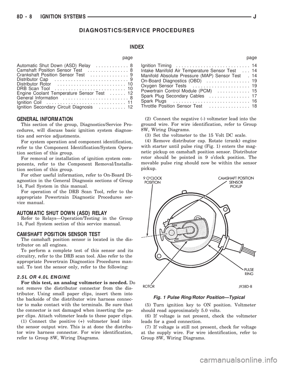
(4) Remove distributor cap. Rotate (crank) engine
with starter until pulse ring (Fig. 1) enters the mag-
netic pickup on camshaft position sensor. Distributor
rotor should be pointed in 9 o'clock position. The
movable pulse ring should now be within the sensor
pickup.
(5) Turn ignition key to ON position. Voltmeter
should read approximately 5.0 volts.
(6) If voltage is not present, check the voltmeter
leads for a good connection.
(7) If voltage is still not present, check for voltage
at the supply wire. For wire identification, refer to
Group 8W, Wiring Diagrams.
Fig. 1 Pulse Ring/Rotor PositionÐTypical
8D - 8 IGNITION SYSTEMSJ
Page 326 of 1784
(4) Using insulated pliers, hold the cable terminal
approximately 12 mm (1/2 in.) from the engine cylin-
der head or block while rotating the engine with the
starter motor. Observe the spark plug cable terminal
for an arc. If steady arcing occurs, it can be expected
that the ignition secondary system is operating cor-
rectly. If steady arcing occurs at the spark plug ca-
bles, but the engine will not start, connect the DRB
scan tool. Refer to the Powertrain Diagnostic Proce-
dures service manual for DRB operation.
FAILURE TO START TEST
To prevent unnecessary diagnostic time and wrong
test results, the previous Checking For Spark test
should be performed prior to this test.
WARNING: SET PARKING BRAKE OR BLOCK THE
DRIVE WHEELS BEFORE PROCEEDING WITH THIS
TEST.
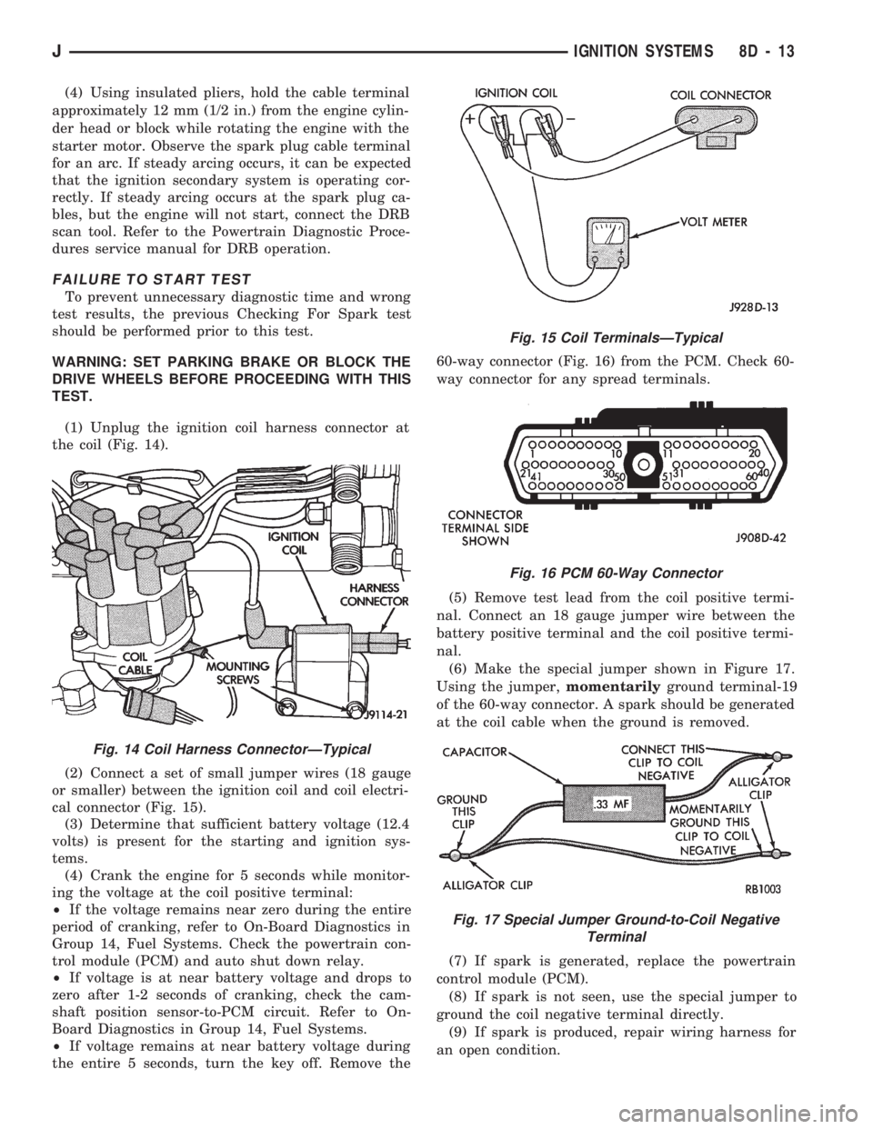
(1) Unplug the ignition coil harness connector at
the coil (Fig. 14).
(2) Connect a set of small jumper wires (18 gauge
or smaller) between the ignition coil and coil electri-
cal connector (Fig. 15).
(3) Determine that sufficient battery voltage (12.4
volts) is present for the starting and ignition sys-
tems.
(4) Crank the engine for 5 seconds while monitor-
ing the voltage at the coil positive terminal:
²If the voltage remains near zero during the entire
period of cranking, refer to On-Board Diagnostics in
Group 14, Fuel Systems. Check the powertrain con-
trol module (PCM) and auto shut down relay.
²If voltage is at near battery voltage and drops to
zero after 1-2 seconds of cranking, check the cam-
shaft position sensor-to-PCM circuit. Refer to On-
Board Diagnostics in Group 14, Fuel Systems.
²If voltage remains at near battery voltage during
the entire 5 seconds, turn the key off. Remove the60-way connector (Fig. 16) from the PCM. Check 60-
way connector for any spread terminals.
(5) Remove test lead from the coil positive termi-
nal. Connect an 18 gauge jumper wire between the
battery positive terminal and the coil positive termi-
nal.
(6) Make the special jumper shown in Figure 17.
Using the jumper,momentarilyground terminal-19
of the 60-way connector. A spark should be generated
at the coil cable when the ground is removed.
(7) If spark is generated, replace the powertrain
control module (PCM).
(8) If spark is not seen, use the special jumper to
ground the coil negative terminal directly.
(9) If spark is produced, repair wiring harness for
an open condition.
Fig. 14 Coil Harness ConnectorÐTypical
Fig. 15 Coil TerminalsÐTypical
Fig. 16 PCM 60-Way Connector
Fig. 17 Special Jumper Ground-to-Coil Negative
Terminal
JIGNITION SYSTEMS 8D - 13
Page 327 of 1784
(10) If spark is not produced, replace the ignition
coil.
IGNITION TIMING
Base (initial) ignition timing is NOT adjustable
on any of the 2.5L 4 cylinder or 4.0L 6 cylinder
engines. Do not attempt to adjust ignition timing
by rotating the distributor.
Do not attempt to modify the distributor hous-
ing to get distributor rotation. Distributor posi-
tion will have no effect on ignition timing.
All ignition timing functions are controlled by the
powertrain control module (PCM). Refer to On-Board
Diagnostics in the Multi-Port Fuel InjectionÐGen-
eral Diagnosis section of Group 14, Fuel Systems for
more information. Also refer to the appropriate Pow-
ertrain Diagnostics Procedures service manual for
operation of the DRB Scan Tool.
INTAKE MANIFOLD AIR TEMPERATURE SENSOR
TEST
To perform a complete test of this sensor and its
circuitry, refer to the DRB scan tool. Also refer to the
appropriate Powertrain Diagnostics Procedures man-
ual. To test the sensor only, refer to the following:
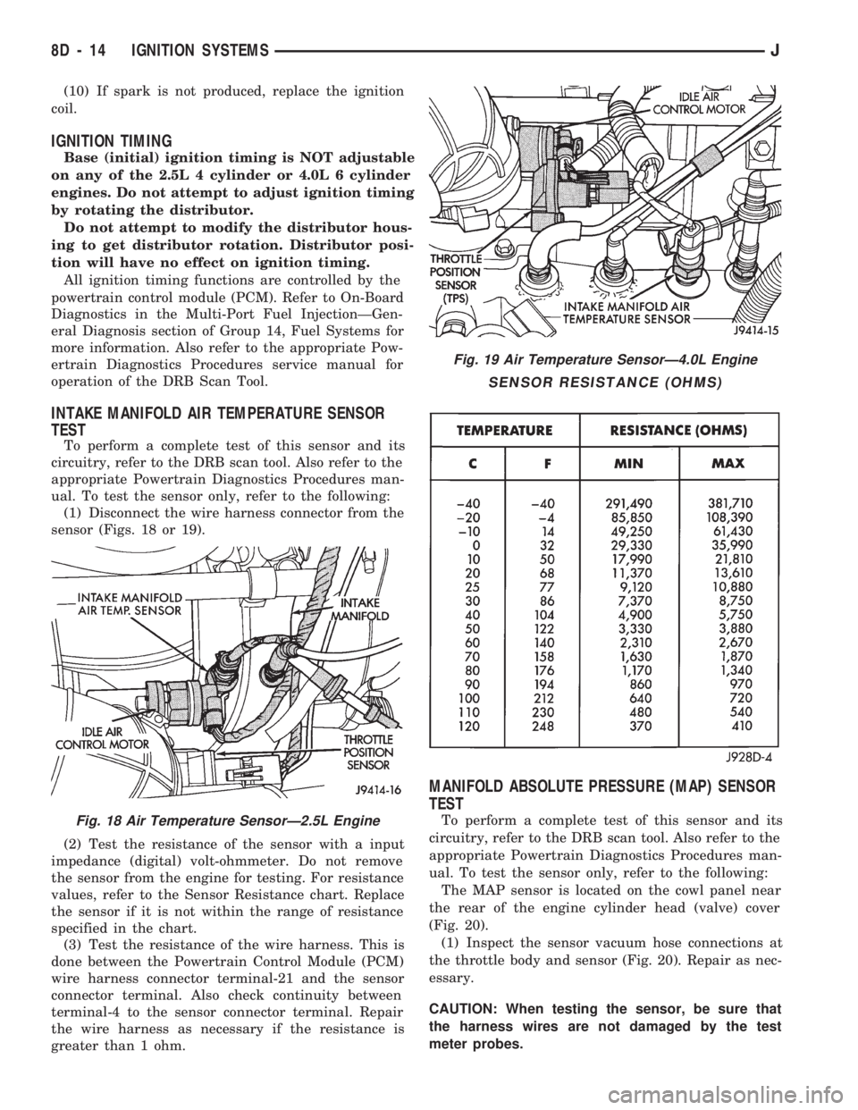
(1) Disconnect the wire harness connector from the
sensor (Figs. 18 or 19).
(2) Test the resistance of the sensor with a input
impedance (digital) volt-ohmmeter. Do not remove
the sensor from the engine for testing. For resistance
values, refer to the Sensor Resistance chart. Replace
the sensor if it is not within the range of resistance
specified in the chart.
(3) Test the resistance of the wire harness. This is
done between the Powertrain Control Module (PCM)
wire harness connector terminal-21 and the sensor
connector terminal. Also check continuity between
terminal-4 to the sensor connector terminal. Repair
the wire harness as necessary if the resistance is
greater than 1 ohm.
MANIFOLD ABSOLUTE PRESSURE (MAP) SENSOR
TEST
To perform a complete test of this sensor and its
circuitry, refer to the DRB scan tool. Also refer to the
appropriate Powertrain Diagnostics Procedures man-
ual. To test the sensor only, refer to the following:
The MAP sensor is located on the cowl panel near
the rear of the engine cylinder head (valve) cover
(Fig. 20).
(1) Inspect the sensor vacuum hose connections at
the throttle body and sensor (Fig. 20). Repair as nec-
essary.
CAUTION: When testing the sensor, be sure that
the harness wires are not damaged by the test
meter probes.Fig. 18 Air Temperature SensorÐ2.5L Engine
Fig. 19 Air Temperature SensorÐ4.0L Engine
SENSOR RESISTANCE (OHMS)
8D - 14 IGNITION SYSTEMSJ
Page 329 of 1784
For diagnostics, refer to the appropriate Powertrain
Diagnostic Procedures service manual for operation
of the DRB scan tool.
SPARK PLUGS
For spark plug removal, cleaning, gap adjustment
and installation, refer to the Component Removal/In-
stallation section of this group.
Faulty carbon and/or gas fouled plugs generally
cause hard starting, but they will clean up at higher
engine speeds. Faulty plugs can be identified in a
number of ways: poor fuel economy, power loss, de-
crease in engine speed, hard starting and, in general,
poor engine performance.
Remove the spark plugs and examine them for
burned electrodes and fouled, cracked or broken por-
celain insulators. Keep plugs arranged in the order
in which they were removed from the engine. An iso-
lated plug displaying an abnormal condition indi-
cates that a problem exists in the corresponding
cylinder. Replace spark plugs at the intervals recom-
mended in the maintenance chart in Group 0, Lubri-
cation and Maintenance.
Spark plugs that have low mileage may be cleaned
and reused if not otherwise defective. Refer to the
following Spark Plug Condition section of this group.
CONDITION
NORMAL OPERATING
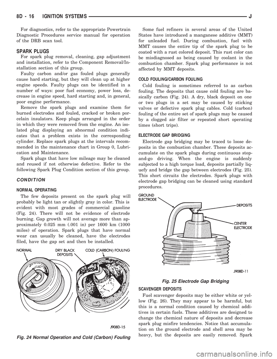
The few deposits present on the spark plug will
probably be light tan or slightly gray in color. This is
evident with most grades of commercial gasoline
(Fig. 24). There will not be evidence of electrode
burning. Gap growth will not average more than ap-
proximately 0.025 mm (.001 in) per 1600 km (1000
miles) of operation. Spark plugs that have normal
wear can usually be cleaned, have the electrodes
filed, have the gap set and then be installed.Some fuel refiners in several areas of the United
States have introduced a manganese additive (MMT)
for unleaded fuel. During combustion, fuel with
MMT causes the entire tip of the spark plug to be
coated with a rust colored deposit. This rust color can
be misdiagnosed as being caused by coolant in the
combustion chamber. Spark plug performance is not
affected by MMT deposits.
COLD FOULING/CARBON FOULING
Cold fouling is sometimes referred to as carbon
fouling. The deposits that cause cold fouling are ba-
sically carbon (Fig. 24). A dry, black deposit on one
or two plugs in a set may be caused by sticking
valves or defective spark plug cables. Cold (carbon)
fouling of the entire set of spark plugs may be caused
by a clogged air filter or repeated short operating
times (short trips).
ELECTRODE GAP BRIDGING
Electrode gap bridging may be traced to loose de-
posits in the combustion chamber. These deposits ac-
cumulate on the spark plugs during continuous stop-
and-go driving. When the engine is suddenly
subjected to a high torque load, deposits partially liq-
uefy and bridge the gap between electrodes (Fig. 25).
This short circuits the electrodes. Spark plugs with
electrode gap bridging can be cleaned using standard
procedures.
SCAVENGER DEPOSITS
Fuel scavenger deposits may be either white or yel-
low (Fig. 26). They may appear to be harmful, but
this is a normal condition caused by chemical addi-
tives in certain fuels. These additives are designed to
change the chemical nature of deposits and decrease
spark plug misfire tendencies. Notice that accumula-
tion on the ground electrode and shell area may be
heavy, but the deposits are easily removed. Spark
Fig. 24 Normal Operation and Cold (Carbon) Fouling
Fig. 25 Electrode Gap Bridging
8D - 16 IGNITION SYSTEMSJ
Page 332 of 1784
With the ignition key in the ON position and en-
gine not running, check the sensor output voltage at
the center terminal wire of the connector. Check this
at idle (throttle plate closed) and at wide open throt-
tle (WOT). At idle, sensor output voltage should be
greater than 200 millivolts. At wide open throttle,
sensor output voltage must be less than 4.8 volts.
The output voltage should increase gradually as the
throttle plate is slowly opened from idle to WOT.
OXYGEN SENSOR TESTS
For diagnosis, removal or installation, refer to
Group 14, Fuel Systems in this manual.
ON-BOARD DIAGNOSTICS (OBD)
FOR IGNITION SYSTEM COMPONENTS
The powertrain control module (PCM) has been
programmed to monitor certain ignition system cir-
cuits:
EXAMPLE:
If a reference signal is not being detected during
engine cranking from the crankshaft position sensor,
a Diagnostic Trouble Code (DTC) number 11 can be
observed at the Check Engine Lamp.
If the problem is sensed in a monitored circuit of-
ten enough to indicate an actual problem, a DTC is
stored. The DTC will be stored in the PCM memory
for eventual display to the service technician. If the
problem is repaired or ceases to exist, the PCM can-
cels the DTC after 51 engine starts.
Certain criteria must be met for a DTC to be en-
tered into PCM memory. The criteria may be a spe-
cific range of engine rpm, engine temperature and/or
input voltage to the PCM.
A DTC indicates that the PCM has recognized an
abnormal signal in a circuit or the system. A DTC
may indicate the result of a failure, but never iden-
tify the failed component directly.
It is possible that a DTC for a monitored circuit
may not be entered into memory even though a mal-
function has occurred. Refer to On-Board Diagnostics
(OBD) in Group 14, Fuel Systems for additional in-
formation.
ACCESSING DIAGNOSTIC TROUBLE CODES
A stored Diagnostic Trouble Code (DTC) can be dis-
played by cycling the ignition key On-Off-On-Off-On
within three seconds and observing the Malfunction
Indicator Lamp. This lamp was formerly referred to
as the Check Engine Lamp. The lamp is located on
the instrument panel.
They can also be displayed through the use of the
Diagnostic Readout Box (DRB) scan tool. The DRB
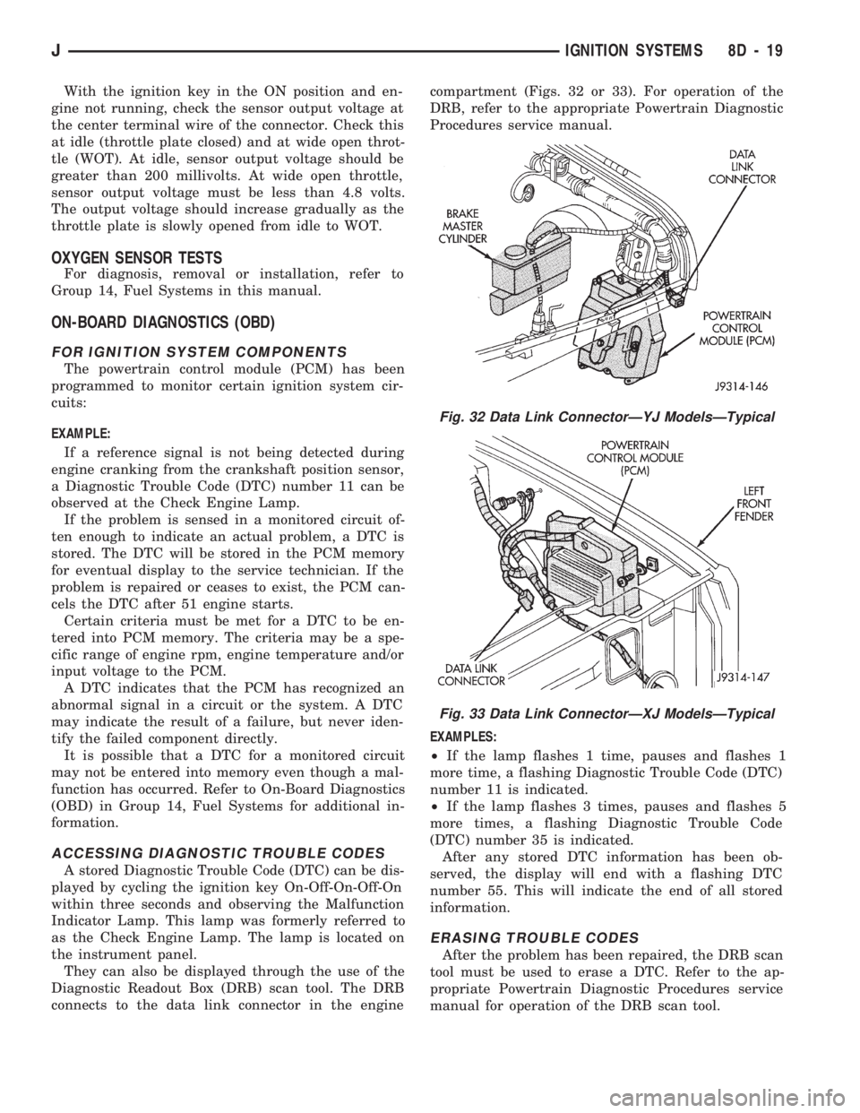
connects to the data link connector in the enginecompartment (Figs. 32 or 33). For operation of the
DRB, refer to the appropriate Powertrain Diagnostic
Procedures service manual.
EXAMPLES:
²If the lamp flashes 1 time, pauses and flashes 1
more time, a flashing Diagnostic Trouble Code (DTC)
number 11 is indicated.
²If the lamp flashes 3 times, pauses and flashes 5
more times, a flashing Diagnostic Trouble Code
(DTC) number 35 is indicated.
After any stored DTC information has been ob-
served, the display will end with a flashing DTC
number 55. This will indicate the end of all stored
information.
ERASING TROUBLE CODES
After the problem has been repaired, the DRB scan
tool must be used to erase a DTC. Refer to the ap-
propriate Powertrain Diagnostic Procedures service
manual for operation of the DRB scan tool.
Fig. 32 Data Link ConnectorÐYJ ModelsÐTypical
Fig. 33 Data Link ConnectorÐXJ ModelsÐTypical
JIGNITION SYSTEMS 8D - 19
Page 335 of 1784
REMOVALÐALL ENGINES
(1) Near the rear of the intake manifold, discon-
nect the pigtail harness (on the sensor) from the
main electrical harness.
(2) Remove the nut holding sensor wire clip to fuel
rail mounting stud.
(3) Depending upon application, remove either the
sensor mounting bolt(s) or nuts.
(4) Remove the sensor.
(5) Remove clip from sensor wire harness.
INSTALLATIONÐALL EXCEPT YJ MODELS
WITH 4.0L ENGINE AND AUTOMATIC
TRANSMISSION
(1) Install the sensor flush against the opening in
the transmission housing.
(2) Install and tighten the two sensor mounting
bolts (or nuts) to 19 Nzm (14 ft. lbs.) torque.
CAUTION: On some models, two bolts used to se-
cure the sensor to the transmission. These bolts
are specially machined to correctly space the unit
to the flywheel. Do not attempt to install any other
bolts.
(3) Connect the electrical connector to the sensor.
(4) Install clip on sensor wire harness.
(5) Install clip over fuel rail mounting stud. Install
clip mounting nut.
INSTALLATIONÐYJ MODELS WITH 4.0L
ENGINE AND AUTOMATIC TRANSMISSION
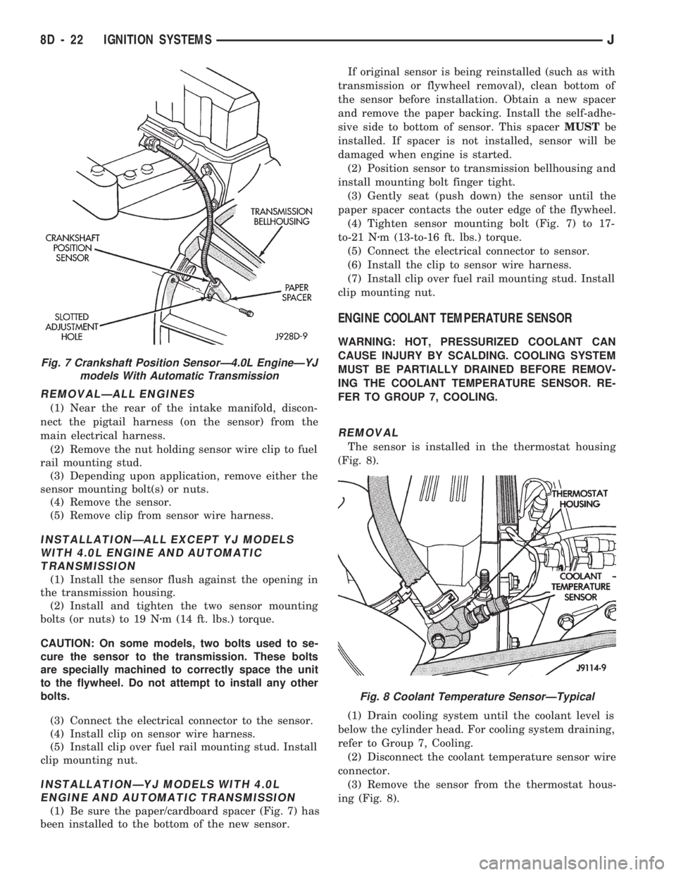
(1) Be sure the paper/cardboard spacer (Fig. 7) has
been installed to the bottom of the new sensor.If original sensor is being reinstalled (such as with
transmission or flywheel removal), clean bottom of
the sensor before installation. Obtain a new spacer
and remove the paper backing. Install the self-adhe-
sive side to bottom of sensor. This spacerMUSTbe
installed. If spacer is not installed, sensor will be
damaged when engine is started.
(2) Position sensor to transmission bellhousing and
install mounting bolt finger tight.
(3) Gently seat (push down) the sensor until the
paper spacer contacts the outer edge of the flywheel.
(4) Tighten sensor mounting bolt (Fig. 7) to 17-
to-21 Nzm (13-to-16 ft. lbs.) torque.
(5) Connect the electrical connector to sensor.
(6) Install the clip to sensor wire harness.
(7) Install clip over fuel rail mounting stud. Install
clip mounting nut.
ENGINE COOLANT TEMPERATURE SENSOR
WARNING: HOT, PRESSURIZED COOLANT CAN
CAUSE INJURY BY SCALDING. COOLING SYSTEM
MUST BE PARTIALLY DRAINED BEFORE REMOV-
ING THE COOLANT TEMPERATURE SENSOR. RE-
FER TO GROUP 7, COOLING.
REMOVAL
The sensor is installed in the thermostat housing
(Fig. 8).
(1) Drain cooling system until the coolant level is
below the cylinder head. For cooling system draining,
refer to Group 7, Cooling.
(2) Disconnect the coolant temperature sensor wire
connector.
(3) Remove the sensor from the thermostat hous-
ing (Fig. 8).
Fig. 7 Crankshaft Position SensorÐ4.0L EngineÐYJ
models With Automatic Transmission
Fig. 8 Coolant Temperature SensorÐTypical
8D - 22 IGNITION SYSTEMSJ
Page 341 of 1784
INSTALLATION
(1) Install MAP sensor to dash panel and secure
with mounting nuts.
(2) Install the MAP sensor vacuum supply hose.
(3) Connect the MAP sensor electrical connector.
OXYGEN (O2S) SENSOR
For diagnostics and removal/installation proce-
dures, refer to Group 14, Fuel Systems, in this man-
ual.
POWERTRAIN CONTROL MODULE (PCM)
The PCM was formerly referred to as the SBEC or
engine controller.
XJ MODELS
On XJ models, the PCM is located in the engine
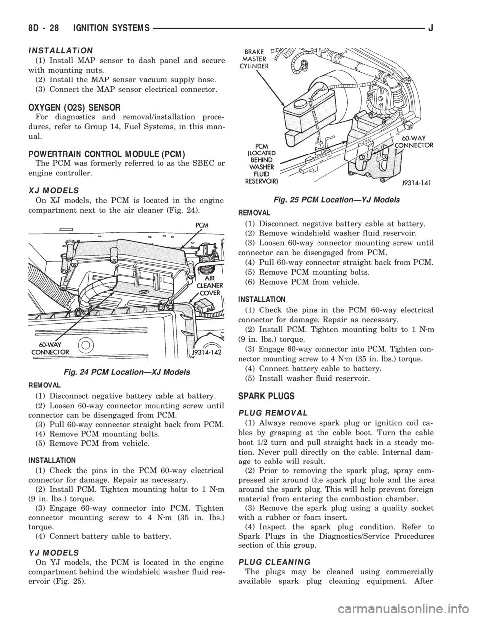
compartment next to the air cleaner (Fig. 24).
REMOVAL
(1) Disconnect negative battery cable at battery.
(2) Loosen 60-way connector mounting screw until
connector can be disengaged from PCM.
(3) Pull 60-way connector straight back from PCM.
(4) Remove PCM mounting bolts.
(5) Remove PCM from vehicle.
INSTALLATION
(1) Check the pins in the PCM 60-way electrical
connector for damage. Repair as necessary.
(2) Install PCM. Tighten mounting bolts to 1 Nzm
(9 in. lbs.) torque.
(3) Engage 60-way connector into PCM. Tighten
connector mounting screw to 4 Nzm (35 in. lbs.)
torque.
(4) Connect battery cable to battery.
YJ MODELS
On YJ models, the PCM is located in the engine
compartment behind the windshield washer fluid res-
ervoir (Fig. 25).REMOVAL
(1) Disconnect negative battery cable at battery.
(2) Remove windshield washer fluid reservoir.
(3) Loosen 60-way connector mounting screw until
connector can be disengaged from PCM.
(4) Pull 60-way connector straight back from PCM.
(5) Remove PCM mounting bolts.
(6) Remove PCM from vehicle.
INSTALLATION
(1) Check the pins in the PCM 60-way electrical
connector for damage. Repair as necessary.
(2) Install PCM. Tighten mounting bolts to 1 Nzm
(9 in. lbs.) torque.
(3) Engage 60-way connector into PCM. Tighten con-
nector mounting screw to 4 Nzm (35 in. lbs.) torque.
(4) Connect battery cable to battery.
(5) Install washer fluid reservoir.
SPARK PLUGS
PLUG REMOVAL
(1) Always remove spark plug or ignition coil ca-
bles by grasping at the cable boot. Turn the cable
boot 1/2 turn and pull straight back in a steady mo-
tion. Never pull directly on the cable. Internal dam-
age to cable will result.
(2) Prior to removing the spark plug, spray com-
pressed air around the spark plug hole and the area
around the spark plug. This will help prevent foreign
material from entering the combustion chamber.
(3) Remove the spark plug using a quality socket
with a rubber or foam insert.
(4) Inspect the spark plug condition. Refer to
Spark Plugs in the Diagnostics/Service Procedures
section of this group.
PLUG CLEANING
The plugs may be cleaned using commercially
available spark plug cleaning equipment. After
Fig. 24 PCM LocationÐXJ Models
Fig. 25 PCM LocationÐYJ Models
8D - 28 IGNITION SYSTEMSJ