seat adjustment JEEP CHEROKEE 1994 Service Repair Manual
[x] Cancel search | Manufacturer: JEEP, Model Year: 1994, Model line: CHEROKEE, Model: JEEP CHEROKEE 1994Pages: 1784, PDF Size: 77.09 MB
Page 32 of 1784
FRONT WHEEL BEARINGS
Only 2WD XJ vehicles are equipped with front
wheel bearings. XJ vehicles have semi-floating axle
shafts and axle shaft bearings that are lubricated via
differential lube oil.
RECOMMENDED MAINTENANCEÐ2WD XJ
VEHICLES
The front wheel bearings should be lubricated (re-
packed) at the same time as front brake pad/caliper
service is conducted.
LUBRICANT SPECIFICATION
Wheel bearings should be lubricated with a lubri-
cant that is identified as NLGI GC-LB lubricant.
INSPECTION/LUBRICATION
(1) Remove the wheel/tire and the disc brake cali-
per.Do not disconnect the caliper brake fluid
hose unless the caliper must also be removed for
maintenance. Support the caliper with a hanger
to prevent brake fluid hose damage.
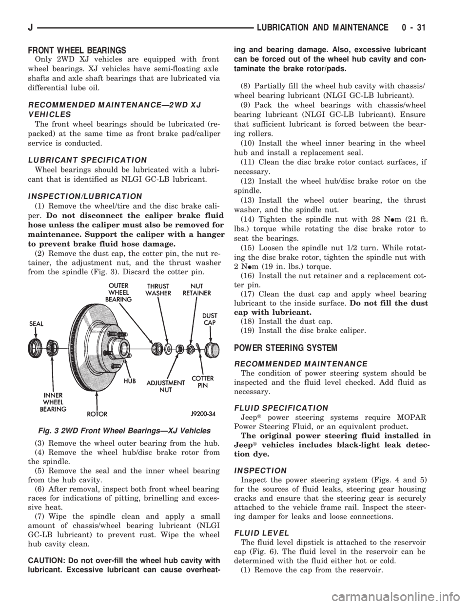
(2) Remove the dust cap, the cotter pin, the nut re-
tainer, the adjustment nut, and the thrust washer
from the spindle (Fig. 3). Discard the cotter pin.
(3) Remove the wheel outer bearing from the hub.
(4) Remove the wheel hub/disc brake rotor from
the spindle.
(5) Remove the seal and the inner wheel bearing
from the hub cavity.
(6) After removal, inspect both front wheel bearing
races for indications of pitting, brinelling and exces-
sive heat.
(7) Wipe the spindle clean and apply a small
amount of chassis/wheel bearing lubricant (NLGI
GC-LB lubricant) to prevent rust. Wipe the wheel
hub cavity clean.
CAUTION: Do not over-fill the wheel hub cavity with
lubricant. Excessive lubricant can cause overheat-ing and bearing damage. Also, excessive lubricant
can be forced out of the wheel hub cavity and con-
taminate the brake rotor/pads.
(8) Partially fill the wheel hub cavity with chassis/
wheel bearing lubricant (NLGI GC-LB lubricant).
(9) Pack the wheel bearings with chassis/wheel
bearing lubricant (NLGI GC-LB lubricant). Ensure
that sufficient lubricant is forced between the bear-
ing rollers.
(10) Install the wheel inner bearing in the wheel
hub and install a replacement seal.
(11) Clean the disc brake rotor contact surfaces, if
necessary.
(12) Install the wheel hub/disc brake rotor on the
spindle.
(13) Install the wheel outer bearing, the thrust
washer, and the spindle nut.
(14) Tighten the spindle nut with 28 NIm (21 ft.
lbs.) torque while rotating the disc brake rotor to
seat the bearings.
(15) Loosen the spindle nut 1/2 turn. While rotat-
ing the disc brake rotor, tighten the spindle nut with
2NIm (19 in. lbs.) torque.
(16) Install the nut retainer and a replacement cot-
ter pin.
(17) Clean the dust cap and apply wheel bearing
lubricant to the inside surface.Do not fill the dust
cap with lubricant.
(18) Install the dust cap.
(19) Install the disc brake caliper.
POWER STEERING SYSTEM
RECOMMENDED MAINTENANCE
The condition of power steering system should be
inspected and the fluid level checked. Add fluid as
necessary.
FLUID SPECIFICATION
Jeeptpower steering systems require MOPAR
Power Steering Fluid, or an equivalent product.
The original power steering fluid installed in
Jeeptvehicles includes black-light leak detec-
tion dye.
INSPECTION
Inspect the power steering system (Figs. 4 and 5)
for the sources of fluid leaks, steering gear housing
cracks and ensure that the steering gear is securely
attached to the vehicle frame rail. Inspect the steer-
ing damper for leaks and loose connections.
FLUID LEVEL
The fluid level dipstick is attached to the reservoir
cap (Fig. 6). The fluid level in the reservoir can be
determined with the fluid either hot or cold.
(1) Remove the cap from the reservoir.
Fig. 3 2WD Front Wheel BearingsÐXJ Vehicles
JLUBRICATION AND MAINTENANCE 0 - 31
Page 39 of 1784
axle assembly to the frame. The lower arms uses
shims at the frame mount to allow for adjustment of
caster and pinion angle. The suspension arm travel
(jounce or rebound) is limited through the use of rub-
ber bumpers.
Suspension components which use rubber bushings
should be tightened at vehicle ride height. This will
prevent premature failure of the bushing and main-
tain ride comfort. Bushings must never be lubricated.
The coil springs control ride quality and maintain
proper ride height. The coil springs mount up in the
fender shield which is part of the unitized body
bracket. A rubber isolator is located between the top
of the spring and the frame. The bottom of the spring
seats on a axle pad and is retained with a clip.
The shock absorbers dampen jounce and rebound of
the vehicle over various road conditions. The top of
the shock absorbers are bolted to the frame. The bot-
tom of the shocks are bolted to the axle spring
bracket.
The stabilizer bar is used to minimize vehicle front
sway during turns. The spring steel bar helps to con-
trol the vehicle body in relationship to the suspen-
sion. The bar extends across the front underside of
the chassis and connects to the frame rails. Links are
connected from the bar to the axle brackets. Stabi-
lizer bar mounts are isolated by rubber bushings.
The track bar is used to minimize front axle side-
to-side movement. The bar is attached to a frame rail
bracket with a ball stud and isolated with a bushing
at the axle bracket.
TUBE AXLE (2WD VEHICLES)
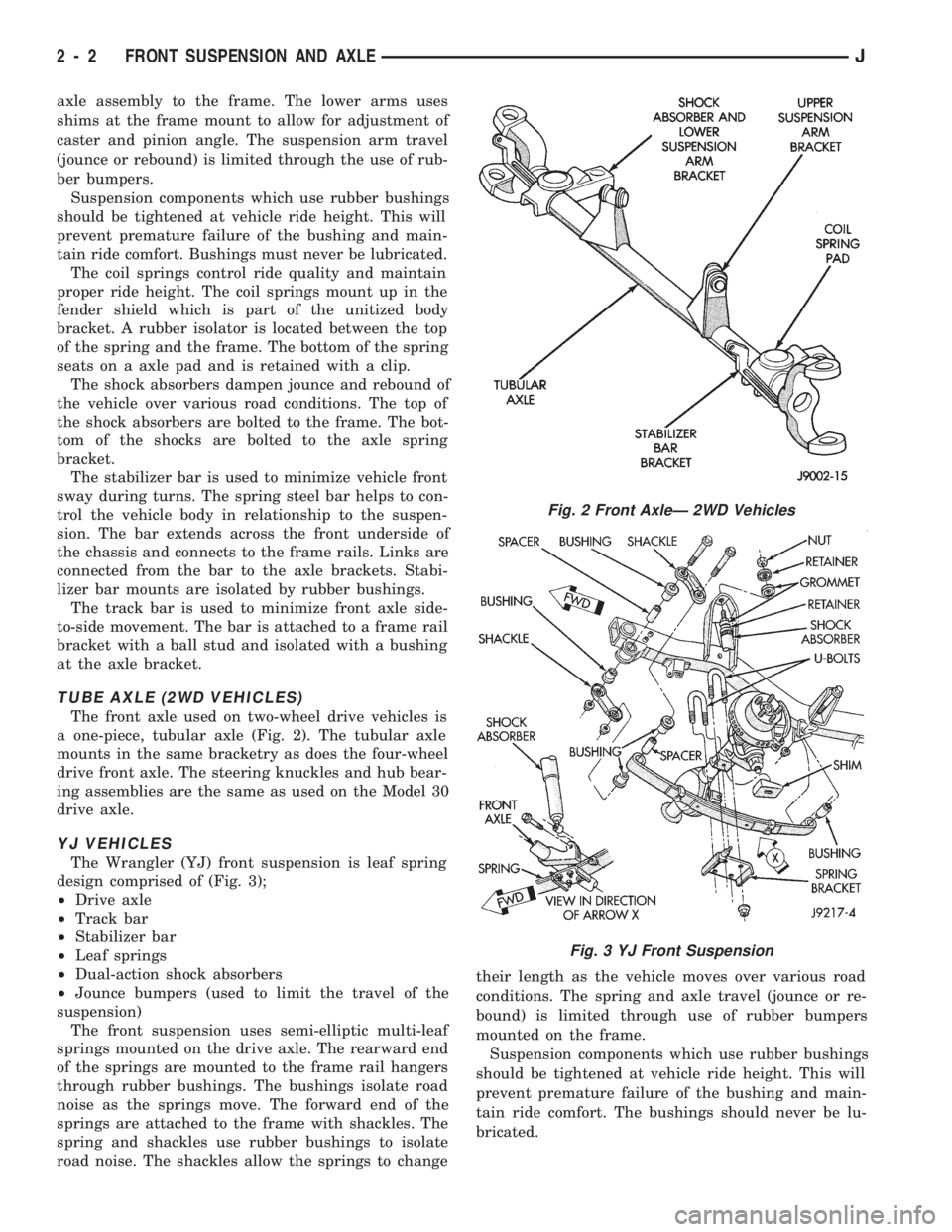
The front axle used on two-wheel drive vehicles is
a one-piece, tubular axle (Fig. 2). The tubular axle
mounts in the same bracketry as does the four-wheel
drive front axle. The steering knuckles and hub bear-
ing assemblies are the same as used on the Model 30
drive axle.
YJ VEHICLES
The Wrangler (YJ) front suspension is leaf spring
design comprised of (Fig. 3);
²Drive axle
²Track bar
²Stabilizer bar
²Leaf springs
²Dual-action shock absorbers
²Jounce bumpers (used to limit the travel of the
suspension)
The front suspension uses semi-elliptic multi-leaf
springs mounted on the drive axle. The rearward end
of the springs are mounted to the frame rail hangers
through rubber bushings. The bushings isolate road
noise as the springs move. The forward end of the
springs are attached to the frame with shackles. The
spring and shackles use rubber bushings to isolate
road noise. The shackles allow the springs to changetheir length as the vehicle moves over various road
conditions. The spring and axle travel (jounce or re-
bound) is limited through use of rubber bumpers
mounted on the frame.
Suspension components which use rubber bushings
should be tightened at vehicle ride height. This will
prevent premature failure of the bushing and main-
tain ride comfort. The bushings should never be lu-
bricated.
Fig. 2 Front AxleÐ 2WD Vehicles
Fig. 3 YJ Front Suspension
2 - 2 FRONT SUSPENSION AND AXLEJ
Page 81 of 1784
BACKLASH AND CONTACT PATTERN ANALYSIS
(1) Rotate assembly several revolutions to seat
bearings. Measure backlash at three equally spaced
locations around the perimeter of the ring gear with
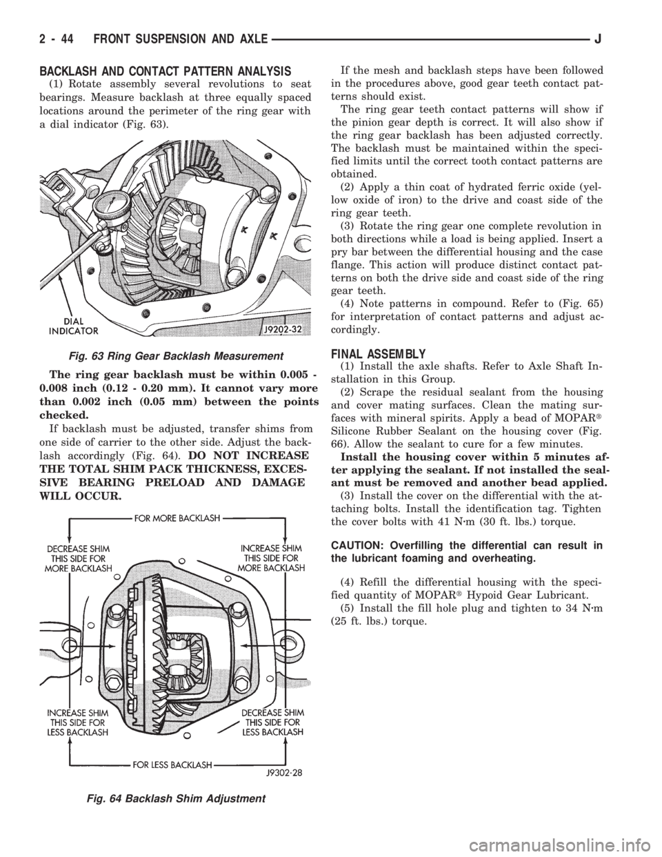
a dial indicator (Fig. 63).
The ring gear backlash must be within 0.005 -
0.008 inch (0.12 - 0.20 mm). It cannot vary more
than 0.002 inch (0.05 mm) between the points
checked.
If backlash must be adjusted, transfer shims from
one side of carrier to the other side. Adjust the back-
lash accordingly (Fig. 64).DO NOT INCREASE
THE TOTAL SHIM PACK THICKNESS, EXCES-
SIVE BEARING PRELOAD AND DAMAGE
WILL OCCUR.If the mesh and backlash steps have been followed
in the procedures above, good gear teeth contact pat-
terns should exist.
The ring gear teeth contact patterns will show if
the pinion gear depth is correct. It will also show if
the ring gear backlash has been adjusted correctly.
The backlash must be maintained within the speci-
fied limits until the correct tooth contact patterns are
obtained.
(2) Apply a thin coat of hydrated ferric oxide (yel-
low oxide of iron) to the drive and coast side of the
ring gear teeth.
(3) Rotate the ring gear one complete revolution in
both directions while a load is being applied. Insert a
pry bar between the differential housing and the case
flange. This action will produce distinct contact pat-
terns on both the drive side and coast side of the ring
gear teeth.
(4) Note patterns in compound. Refer to (Fig. 65)
for interpretation of contact patterns and adjust ac-
cordingly.
FINAL ASSEMBLY
(1) Install the axle shafts. Refer to Axle Shaft In-
stallation in this Group.
(2) Scrape the residual sealant from the housing
and cover mating surfaces. Clean the mating sur-
faces with mineral spirits. Apply a bead of MOPARt
Silicone Rubber Sealant on the housing cover (Fig.
66). Allow the sealant to cure for a few minutes.
Install the housing cover within 5 minutes af-
ter applying the sealant. If not installed the seal-
ant must be removed and another bead applied.
(3) Install the cover on the differential with the at-
taching bolts. Install the identification tag. Tighten
the cover bolts with 41 Nzm (30 ft. lbs.) torque.
CAUTION: Overfilling the differential can result in
the lubricant foaming and overheating.
(4) Refill the differential housing with the speci-
fied quantity of MOPARtHypoid Gear Lubricant.
(5) Install the fill hole plug and tighten to 34 Nzm
(25 ft. lbs.) torque.Fig. 63 Ring Gear Backlash Measurement
Fig. 64 Backlash Shim Adjustment
2 - 44 FRONT SUSPENSION AND AXLEJ
Page 158 of 1784
assembled, they will not function. In addition, since
the adjuster mechanism only works during reverse
stops, it is important that complete stops be made.
The adjuster mechanism does not operate when roll-
ing stops are made in reverse. The vehicle must be
brought to a complete halt before the adjuster lever
will turn the adjuster screw.
A condition where the parking brakes do not hold,
will most probably be due to a wheel brake compo-
nent.
Items to look for when diagnosing a parking brake
problem, are:
²rear brakeshoe wear
²rear brakedrum wear
²brakedrums machined beyond allowable diameter
(oversize)
²parking brake front cable not secured to lever
²parking brake rear cable seized
²parking brake strut reversed
²parking brake strut not seated in both shoes
²parking brake lever not seated in secondary shoe
²parking brake lever or brakeshoe bind on support
plate
²brakeshoes reversed
²adjuster screws seized
²adjuster screws reversed
²holddown or return springs misassembled or lack
tension
²wheel cylinder pistons seized
Brake drums that are machined oversize are diffi-
cult to identify. If oversize drums are suspected, the
diameter of the braking surface will have to be
checked with an accurate drum gauge. Oversize
drums will cause low brake pedal and lack of park-
ing brake holding ability.
Improper parking brake strut and lever installa-
tion will result in unsatisfactory parking brake oper-
ation. Intermixing the adjuster screws will cause
drag, bind and pull along with poor parking brake
operation.
Parking brake adjustment and parts replacement
procedures are described in the Parking Brake sec-
tion.
MASTER CYLINDER/POWER BOOSTER TEST
(1) Start engine and check booster vacuum hose
connections. Hissing noise indicates vacuum leak.
Correct any vacuum leak before proceeding.
(2) Stop engine and shift transmission into Neu-
tral.
(3) Pump brake pedal until all vacuum reserve in
booster is depleted.
(4) Press and hold brake pedal under light foot
pressure.
(a) If pedal holds firm, proceed to step (5).
(b) If pedal does not hold firm and falls away,
master cylinder is faulty (internal leakage). Over-
haul or replace cylinder.(5) Start engine and note pedal action.
(a) If pedal falls away slightly under light foot
pressure then holds firm, proceed to step (6).
(b) If no pedal action is discernible, power
booster or vacuum check valve is faulty. Install
known good check valve and repeat steps (2)
through (5).
(6) Rebuild booster vacuum reserve as follows: Re-
lease brake pedal. Increase engine speed to 1500
rpm, close throttle and immediately turn off ignition.
(7) Wait a minimum of 90 seconds and try brake
action again. Booster should provide two or more
vacuum assisted pedal applications. If vacuum assist
is not provided, perform booster and check valve vac-
uum tests.
POWER BOOSTER CHECK VALVE TEST
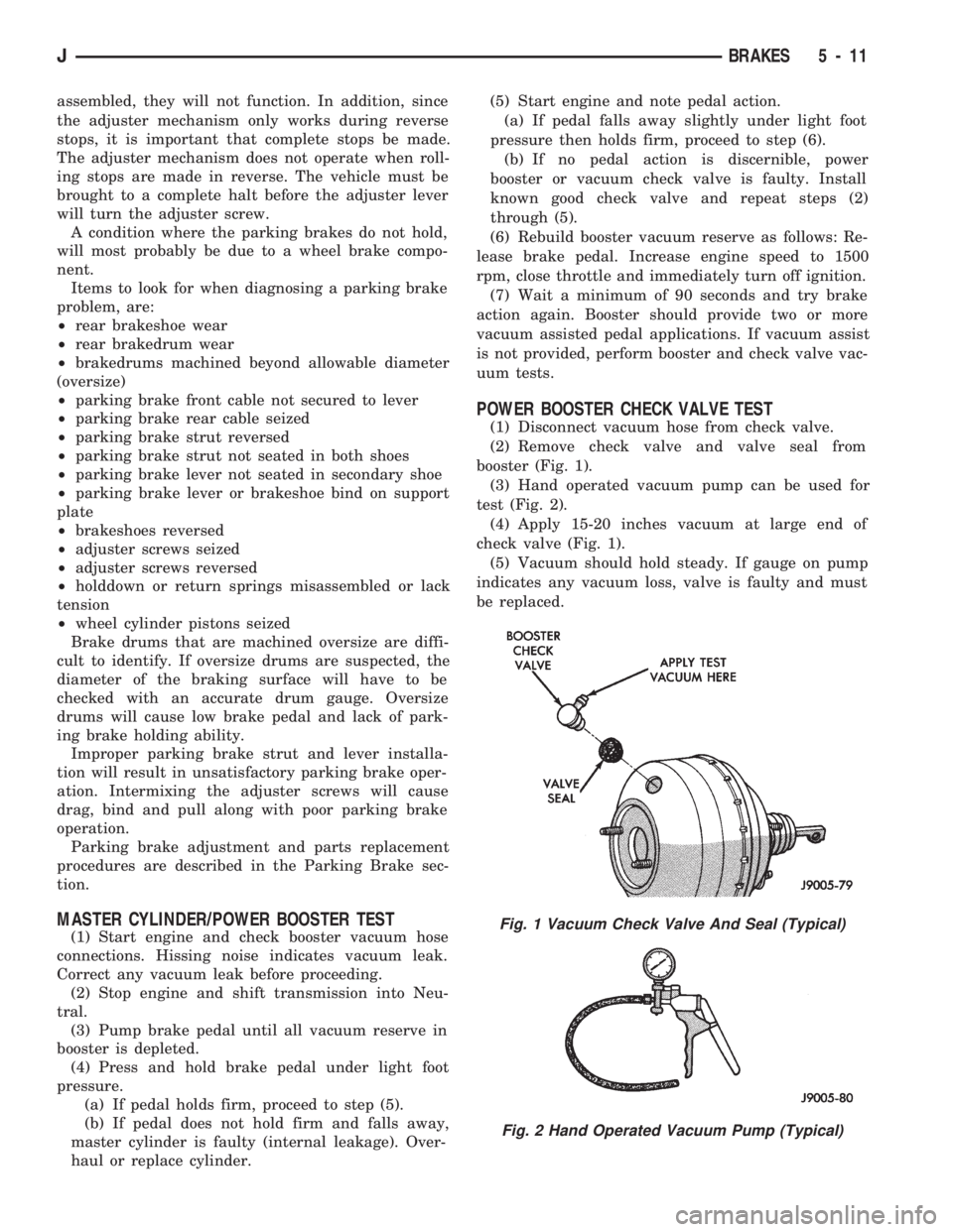
(1) Disconnect vacuum hose from check valve.
(2) Remove check valve and valve seal from
booster (Fig. 1).
(3) Hand operated vacuum pump can be used for
test (Fig. 2).
(4) Apply 15-20 inches vacuum at large end of
check valve (Fig. 1).
(5) Vacuum should hold steady. If gauge on pump
indicates any vacuum loss, valve is faulty and must
be replaced.
Fig. 1 Vacuum Check Valve And Seal (Typical)
Fig. 2 Hand Operated Vacuum Pump (Typical)
JBRAKES 5 - 11
Page 177 of 1784
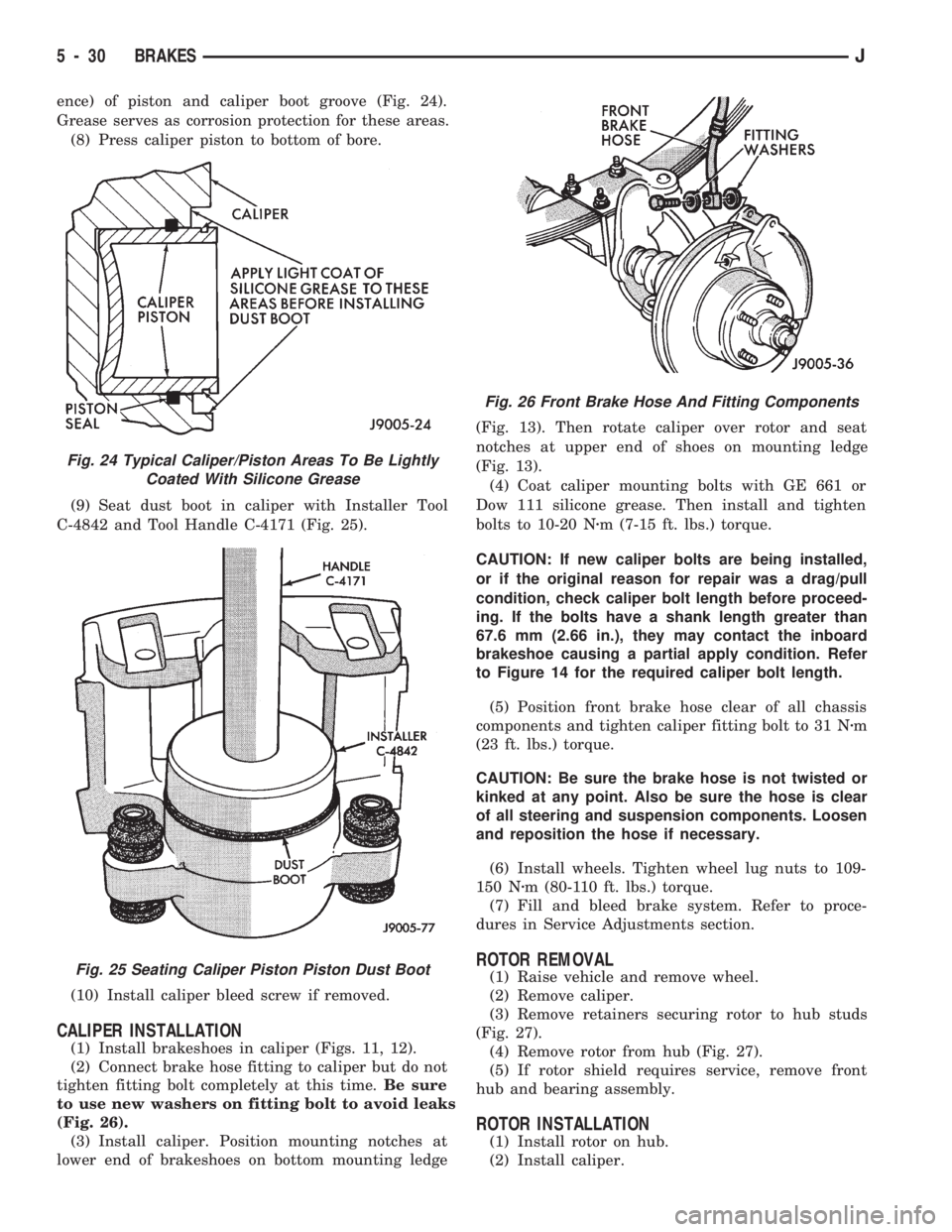
ence) of piston and caliper boot groove (Fig. 24).
Grease serves as corrosion protection for these areas.
(8) Press caliper piston to bottom of bore.
(9) Seat dust boot in caliper with Installer Tool
C-4842 and Tool Handle C-4171 (Fig. 25).
(10) Install caliper bleed screw if removed.
CALIPER INSTALLATION
(1) Install brakeshoes in caliper (Figs. 11, 12).
(2) Connect brake hose fitting to caliper but do not
tighten fitting bolt completely at this time.Be sure
to use new washers on fitting bolt to avoid leaks
(Fig. 26).
(3) Install caliper. Position mounting notches at
lower end of brakeshoes on bottom mounting ledge(Fig. 13). Then rotate caliper over rotor and seat
notches at upper end of shoes on mounting ledge
(Fig. 13).
(4) Coat caliper mounting bolts with GE 661 or
Dow 111 silicone grease. Then install and tighten
bolts to 10-20 Nzm (7-15 ft. lbs.) torque.
CAUTION: If new caliper bolts are being installed,
or if the original reason for repair was a drag/pull
condition, check caliper bolt length before proceed-
ing. If the bolts have a shank length greater than
67.6 mm (2.66 in.), they may contact the inboard
brakeshoe causing a partial apply condition. Refer
to Figure 14 for the required caliper bolt length.
(5) Position front brake hose clear of all chassis
components and tighten caliper fitting bolt to 31 Nzm
(23 ft. lbs.) torque.
CAUTION: Be sure the brake hose is not twisted or
kinked at any point. Also be sure the hose is clear
of all steering and suspension components. Loosen
and reposition the hose if necessary.
(6) Install wheels. Tighten wheel lug nuts to 109-
150 Nzm (80-110 ft. lbs.) torque.
(7) Fill and bleed brake system. Refer to proce-
dures in Service Adjustments section.
ROTOR REMOVAL
(1) Raise vehicle and remove wheel.
(2) Remove caliper.
(3) Remove retainers securing rotor to hub studs
(Fig. 27).
(4) Remove rotor from hub (Fig. 27).
(5) If rotor shield requires service, remove front
hub and bearing assembly.
ROTOR INSTALLATION
(1) Install rotor on hub.
(2) Install caliper.
Fig. 24 Typical Caliper/Piston Areas To Be Lightly
Coated With Silicone Grease
Fig. 25 Seating Caliper Piston Piston Dust Boot
Fig. 26 Front Brake Hose And Fitting Components
5 - 30 BRAKESJ
Page 196 of 1784
Clean the reservoir and caps thoroughly before
checking level or adding fluid. Cap open lines and
hoses during service to prevent dirt entry.
Dirt or foreign material entering the ABS hydrau-
lic system through the reservoir opening will circu-
late within the system. The result will be poor brake
performance and possible component failure. Use
clean, fresh fluid only to top off, or refill the system.
WHEEL SENSOR AIR GAP ADJUSTMENT
Only rear sensor air gap is adjustable. The front
sensors are fixed and cannot be adjusted.
A rear sensor air gap adjustment is only
needed when reinstalling an original sensor. Re-
placement sensors have an air gap spacer at-
tached to the sensor pickup face. The spacer
establishes correct air gap when pressed against
the tone ring during installation. As the tone
ring rotates, it peels the spacer off the sensor to
create the required air gap.
Preferred rear sensor air gap is 1.1 mm (0.043 in.).
Acceptable air gap range is 0.92 to 1.275 mm (0.036
to 0.050 in.).
Front sensor air gap is not adjustable. The front
sensors are fixed in position and cannot be adjusted.
Front sensor air gap can only be checked. Air gap
should be 0.040 to 1.3 mm (0.0157 to 0.051 in.). If
front sensor air gap is incorrect, the sensor is either
loose, or damaged.
FRONT WHEEL SENSOR REMOVAL
(1) Raise vehicle and turn wheel outward for eas-
ier access to sensor.
(2) Remove sensor wire from mounting brackets.
(3) Clean sensor and surrounding area before removal.
(4) Remove bolt attaching sensor to steering
knuckle and remove sensor.
(5) Unseat grommet retaining sensor wire in wheel
house panel.
(6) In engine compartment, disconnect sensor wire con-
nector at harness plug. Then remove sensor and wire.
FRONT WHEEL SENSOR INSTALLATION
(1) Apply Mopar Lock N' Seal or Loctite 242 to
bolt that attaches sensor to steering knuckle. Use
new sensor bolt if original bolt is worn or damaged.
(2) Position sensor on steering knuckle. Seat sen-
sor locating tab in hole in knuckle and install sensor
attaching bolt finger tight.
(3) Tighten sensor bolt to 14 NIm (11 ft. lbs.) torque.
(4) Attach sensor wire to steering knuckle bracket
with grommets on sensor wire.
(5) Route sensor wire forward and behind shock
absorber. Then attach sensor wire to spring seat
bracket with grommets on sensor wire.
(6) Route sensor wire to outer sill bracket. Remove
all twists or kinks from wire.(7) Attach sensor wire to sill bracket with grom-
met. Be sure wire is free of twists and kinks.
(8) Verify sensor wire routing. Wire should loop
forward and above sill bracket. Loose end of wire
should be below sill bracket and towards brake hose.
(9) Seat sensor wire grommet in body panel and
clip wire to brake line at grommet location.
(10) Connect sensor wire to harness in engine com-
partment.
REAR WHEEL SENSOR REMOVAL
(1) On XJ models, if separate connectors are not
used to attach sensor harness to each sensor wire,
proceed as follows:
(a) Raise and fold rear seat forward for access to
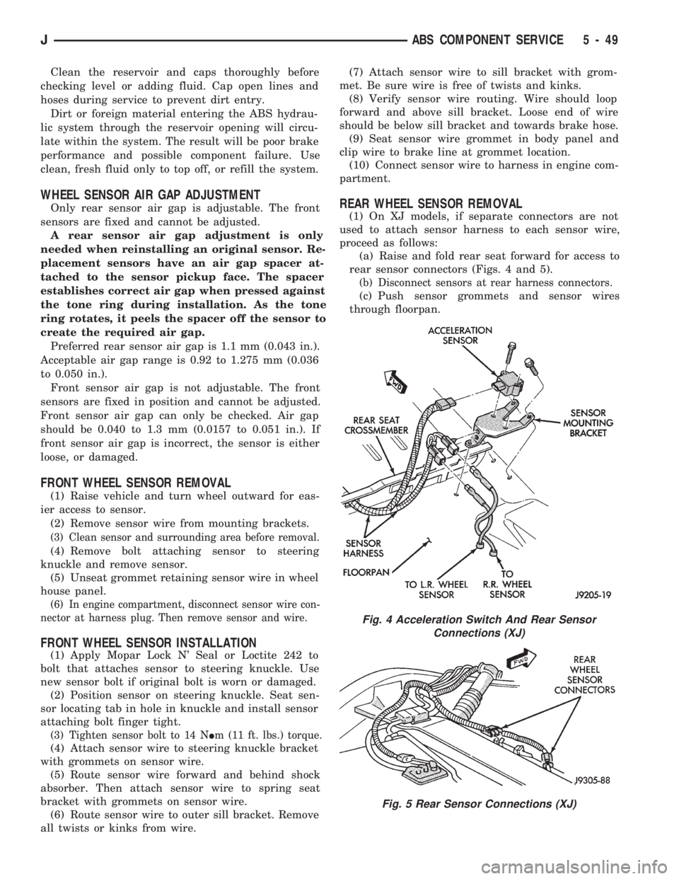
rear sensor connectors (Figs. 4 and 5).
(b) Disconnect sensors at rear harness connectors.
(c) Push sensor grommets and sensor wires
through floorpan.
Fig. 4 Acceleration Switch And Rear Sensor
Connections (XJ)
Fig. 5 Rear Sensor Connections (XJ)
JABS COMPONENT SERVICE 5 - 49
Page 197 of 1784
(2) Raise vehicle.
(3) Disconnect sensor wires at rear axle connectors.
(4) Remove wheel and tire assembly.
(5) Remove brake drum.
(6) Remove clips securing sensor wires to brake
lines or rear axle and rear brake hose.
(7) Unseat sensor support plate grommet.
(8) Remove bolt attaching sensor to bracket and
remove sensor.
REAR WHEEL SENSOR INSTALLATION
(1) Insert sensor wire through support plate hole
and seat sensor grommet in support plate.
(2) Apply Mopar Lock N' Seal or Loctite 242 to
original sensor bolt. Use new bolt if original is worn
or damaged.
(3) Install sensor bolt finger tight only at this
time.
(4) Set sensor air gap as follows:
(a) Iforiginal sensoris being installed, remove
any remaining pieces of cardboard spacer from sen-
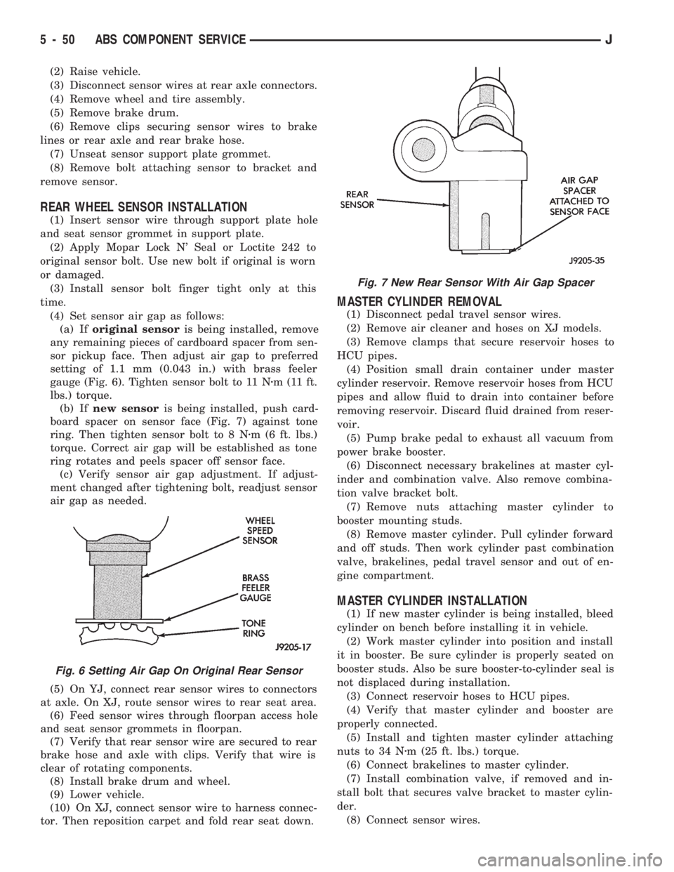
sor pickup face. Then adjust air gap to preferred
setting of 1.1 mm (0.043 in.) with brass feeler
gauge (Fig. 6). Tighten sensor bolt to 11 Nzm (11 ft.
lbs.) torque.
(b) Ifnew sensoris being installed, push card-
board spacer on sensor face (Fig. 7) against tone
ring. Then tighten sensor bolt to 8 Nzm (6 ft. lbs.)
torque. Correct air gap will be established as tone
ring rotates and peels spacer off sensor face.
(c) Verify sensor air gap adjustment. If adjust-
ment changed after tightening bolt, readjust sensor
air gap as needed.
(5) On YJ, connect rear sensor wires to connectors
at axle. On XJ, route sensor wires to rear seat area.
(6) Feed sensor wires through floorpan access hole
and seat sensor grommets in floorpan.
(7) Verify that rear sensor wire are secured to rear
brake hose and axle with clips. Verify that wire is
clear of rotating components.
(8) Install brake drum and wheel.
(9) Lower vehicle.
(10) On XJ, connect sensor wire to harness connec-
tor. Then reposition carpet and fold rear seat down.
MASTER CYLINDER REMOVAL
(1) Disconnect pedal travel sensor wires.
(2) Remove air cleaner and hoses on XJ models.
(3) Remove clamps that secure reservoir hoses to
HCU pipes.
(4) Position small drain container under master
cylinder reservoir. Remove reservoir hoses from HCU
pipes and allow fluid to drain into container before
removing reservoir. Discard fluid drained from reser-
voir.
(5) Pump brake pedal to exhaust all vacuum from
power brake booster.
(6) Disconnect necessary brakelines at master cyl-
inder and combination valve. Also remove combina-
tion valve bracket bolt.
(7) Remove nuts attaching master cylinder to
booster mounting studs.
(8) Remove master cylinder. Pull cylinder forward
and off studs. Then work cylinder past combination
valve, brakelines, pedal travel sensor and out of en-
gine compartment.
MASTER CYLINDER INSTALLATION
(1) If new master cylinder is being installed, bleed
cylinder on bench before installing it in vehicle.
(2) Work master cylinder into position and install
it in booster. Be sure cylinder is properly seated on
booster studs. Also be sure booster-to-cylinder seal is
not displaced during installation.
(3) Connect reservoir hoses to HCU pipes.
(4) Verify that master cylinder and booster are
properly connected.
(5) Install and tighten master cylinder attaching
nuts to 34 Nzm (25 ft. lbs.) torque.
(6) Connect brakelines to master cylinder.
(7) Install combination valve, if removed and in-
stall bolt that secures valve bracket to master cylin-
der.
(8) Connect sensor wires.
Fig. 6 Setting Air Gap On Original Rear Sensor
Fig. 7 New Rear Sensor With Air Gap Spacer
5 - 50 ABS COMPONENT SERVICEJ
Page 209 of 1784
(2) Position pedal assembly on panel and install
mounting stud nuts and pedal-to-dash bolt.
(3) Install ground wire on upper end of pedal-to-
dash bolt and secure wire with attaching nut.
(4) Connect warning light switch wire to pedal
connector.
(5) Install dash-to-instrument panel brace rod, if
equipped.
(6) Raise vehicle and adjust brake cables. Refer to
procedure in Service Adjustment section.
PARKING BRAKE REAR CABLE REPLACEMENT (XJ)
(1) Raise vehicle and loosen equalizer nuts until
rear cables are slack.
(2) Disengage cable from equalizer and remove ca-
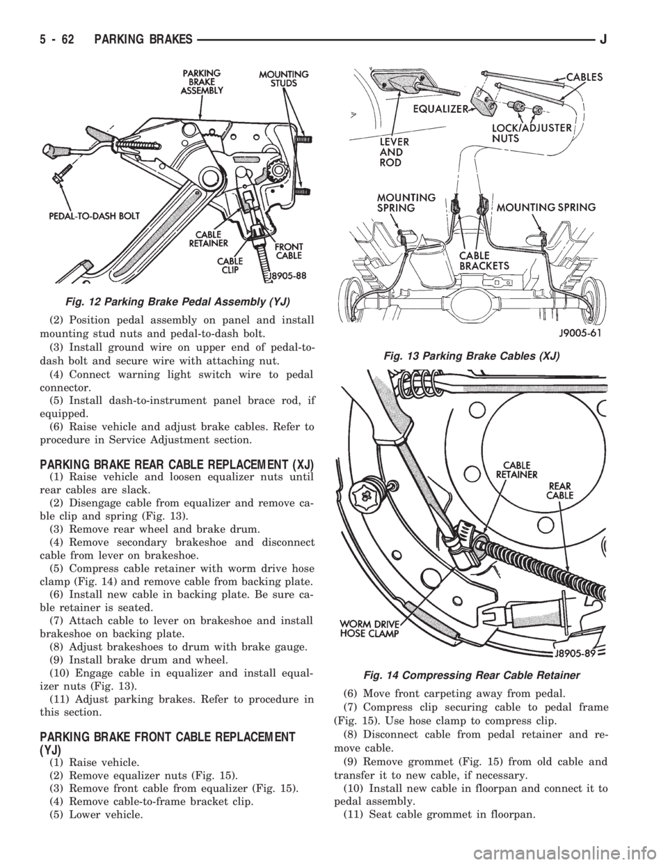
ble clip and spring (Fig. 13).
(3) Remove rear wheel and brake drum.
(4) Remove secondary brakeshoe and disconnect
cable from lever on brakeshoe.
(5) Compress cable retainer with worm drive hose
clamp (Fig. 14) and remove cable from backing plate.
(6) Install new cable in backing plate. Be sure ca-
ble retainer is seated.
(7) Attach cable to lever on brakeshoe and install
brakeshoe on backing plate.
(8) Adjust brakeshoes to drum with brake gauge.
(9) Install brake drum and wheel.
(10) Engage cable in equalizer and install equal-
izer nuts (Fig. 13).
(11) Adjust parking brakes. Refer to procedure in
this section.
PARKING BRAKE FRONT CABLE REPLACEMENT
(YJ)
(1) Raise vehicle.
(2) Remove equalizer nuts (Fig. 15).
(3) Remove front cable from equalizer (Fig. 15).
(4) Remove cable-to-frame bracket clip.
(5) Lower vehicle.(6) Move front carpeting away from pedal.
(7) Compress clip securing cable to pedal frame
(Fig. 15). Use hose clamp to compress clip.
(8) Disconnect cable from pedal retainer and re-
move cable.
(9) Remove grommet (Fig. 15) from old cable and
transfer it to new cable, if necessary.
(10) Install new cable in floorpan and connect it to
pedal assembly.
(11) Seat cable grommet in floorpan.
Fig. 12 Parking Brake Pedal Assembly (YJ)
Fig. 13 Parking Brake Cables (XJ)
Fig. 14 Compressing Rear Cable Retainer
5 - 62 PARKING BRAKESJ
Page 213 of 1784
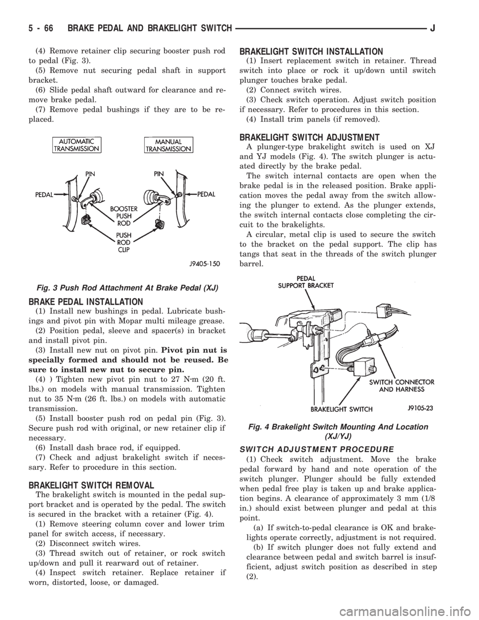
(4) Remove retainer clip securing booster push rod
to pedal (Fig. 3).
(5) Remove nut securing pedal shaft in support
bracket.
(6) Slide pedal shaft outward for clearance and re-
move brake pedal.
(7) Remove pedal bushings if they are to be re-
placed.
BRAKE PEDAL INSTALLATION
(1) Install new bushings in pedal. Lubricate bush-
ings and pivot pin with Mopar multi mileage grease.
(2) Position pedal, sleeve and spacer(s) in bracket
and install pivot pin.
(3) Install new nut on pivot pin.Pivot pin nut is
specially formed and should not be reused. Be
sure to install new nut to secure pin.
(4) ) Tighten new pivot pin nut to 27 Nzm (20 ft.
lbs.) on models with manual transmission. Tighten
nut to 35 Nzm (26 ft. lbs.) on models with automatic
transmission.
(5) Install booster push rod on pedal pin (Fig. 3).
Secure push rod with original, or new retainer clip if
necessary.
(6) Install dash brace rod, if equipped.
(7) Check and adjust brakelight switch if neces-
sary. Refer to procedure in this section.
BRAKELIGHT SWITCH REMOVAL
The brakelight switch is mounted in the pedal sup-
port bracket and is operated by the pedal. The switch
is secured in the bracket with a retainer (Fig. 4).
(1) Remove steering column cover and lower trim
panel for switch access, if necessary.
(2) Disconnect switch wires.
(3) Thread switch out of retainer, or rock switch
up/down and pull it rearward out of retainer.
(4) Inspect switch retainer. Replace retainer if
worn, distorted, loose, or damaged.
BRAKELIGHT SWITCH INSTALLATION
(1) Insert replacement switch in retainer. Thread
switch into place or rock it up/down until switch
plunger touches brake pedal.
(2) Connect switch wires.
(3) Check switch operation. Adjust switch position
if necessary. Refer to procedures in this section.
(4) Install trim panels (if removed).
BRAKELIGHT SWITCH ADJUSTMENT
A plunger-type brakelight switch is used on XJ
and YJ models (Fig. 4). The switch plunger is actu-
ated directly by the brake pedal.
The switch internal contacts are open when the
brake pedal is in the released position. Brake appli-
cation moves the pedal away from the switch allow-
ing the plunger to extend. As the plunger extends,
the switch internal contacts close completing the cir-
cuit to the brakelights.
A circular, metal clip is used to secure the switch
to the bracket on the pedal support. The clip has
tangs that seat in the threads of the switch plunger
barrel.
SWITCH ADJUSTMENT PROCEDURE
(1) Check switch adjustment. Move the brake
pedal forward by hand and note operation of the
switch plunger. Plunger should be fully extended
when pedal free play is taken up and brake applica-
tion begins. A clearance of approximately 3 mm (1/8
in.) should exist between plunger and pedal at this
point.
(a) If switch-to-pedal clearance is OK and brake-
lights operate correctly, adjustment is not required.
(b) If switch plunger does not fully extend and
clearance between pedal and switch barrel is insuf-
ficient, adjust switch position as described in step
(2).
Fig. 3 Push Rod Attachment At Brake Pedal (XJ)
Fig. 4 Brakelight Switch Mounting And Location
(XJ/YJ)
5 - 66 BRAKE PEDAL AND BRAKELIGHT SWITCHJ
Page 306 of 1784
OVERHEAD CONSOLE
CONTENTS
page page
COMPASS REPAIR PROCEDURES.......... 4
CONSOLE REPAIR PROCEDURES........... 6
DESCRIPTION........................... 1DIAGNOSTIC PROCEDURES............... 1
THERMOMETER AND SENSOR SYSTEM REPAIR
PROCEDURES......................... 6
DESCRIPTION
The overhead console includes:
²a compass/temperature display
²reading and courtesy lights for the front and rear
seats
²the receiver for the keyless entry system
²storage compartment for remote garage door
opener
²storage compartment for sunglasses.
COMPASS
The compass will display the direction the vehicle
is pointed, using the eight major compass headings
(Examples: North is ``N'', Northeast is ``NE''). It does
not display the headings in actual degrees. The dis-
play is turned on/off using the TEMP/COMP button
on the left of the display.
The compass is a self calibrating unit that should
not require recalibration. The only calibration that
may prove necessary is to drive the vehicle in 3 com-
plete circles, on level ground, in not less than 48 sec-
onds. This will ``reorient'' the unit to its vehicle. The
unit also will compensate for magnetism the vehicle
may acquire during its life. Care should be used to
avoid putting anything magnetic on the roof of the
vehicle.
The unit can compensate for some magnetic fields
in the body. The use of magnetic attachments like
antenna mounts or repair order ``hats'' placed di-
rectly on the roof can exceed the compensation abil-
ity of the unit. Magnetic bit drivers used on the
fasteners to hold the assembly to the roof header can
also affect operation. If the vehicle roof should be-
come magnetized, then the degaussing and calibra-
tion procedures may be required to restore proper
operation.
If the compass functions but accuracy is suspect, it
may be necessary to perform a variation adjustment.
This procedure allows the unit to accommodate vari-
ations in the earth's magnetic field strength based on
geographic location.
If the compass has blanked out and only CAL
appears, degaussing may be necessary to re-
move residual magnetic fields.
THERMOMETER
The ambient temperature display can be changed
from Fahrenheit to Celsius using the U.S./METRIC
button on the right of the display. The temperature
reported is not an instant reading of conditions but
an average temperature. It may take the unit several
minutes to react to a major change such as driving
out of a heated garage into winter temperatures.
When the ignition switch is turned OFF, the last
displayed temperature reading stays in memory.
When the ignition switch is turned ON again the
thermometer will display the memory temperature
for one minute; then update the display to the actual
temperature within five minutes.
READING AND COURTESY LAMPS
All reading and courtesy lamps in the overhead
console are activated by the door courtesy circuit.
When all four doors and the liftgate are closed the
lamps can be activated by depressing the correspond-
ing lens. When any door or the liftgate is open, the
switches are disabled. They will not turn the lamps
off.
MAP AND COURTESY LAMPS
These lamps offer several unique features. Both the
map and courtesy lamps can be turned on with the
integral ``Soft Touch'' switch. Pushing this switch en-
ergizes an electrical circuit, which in turn directs
power to the light. The map lamps are unaffected by
the door switches, while the courtesy lamps are
turned on with the opening of any door. When any
door is open, the ``Soft Touch'' switches are disabled,
you cannot turn the lights off with these switches.
DIAGNOSTIC PROCEDURES
Follow the appropriate diagnostic flow chart:
²Chart 1 describes the procedures for compass and
display problems.
²Chart 2 describes the procedures for illumination
lamp problems.
²Chart 3 describes the procedures for outside tem-
perature measuring problems.
JOVERHEAD CONSOLE 8C - 1